cd storage MITSUBISHI 3000GT 1992 2.G Owner's Guide
[x] Cancel search | Manufacturer: MITSUBISHI, Model Year: 1992, Model line: 3000GT, Model: MITSUBISHI 3000GT 1992 2.GPages: 738, PDF Size: 35.06 MB
Page 237 of 738
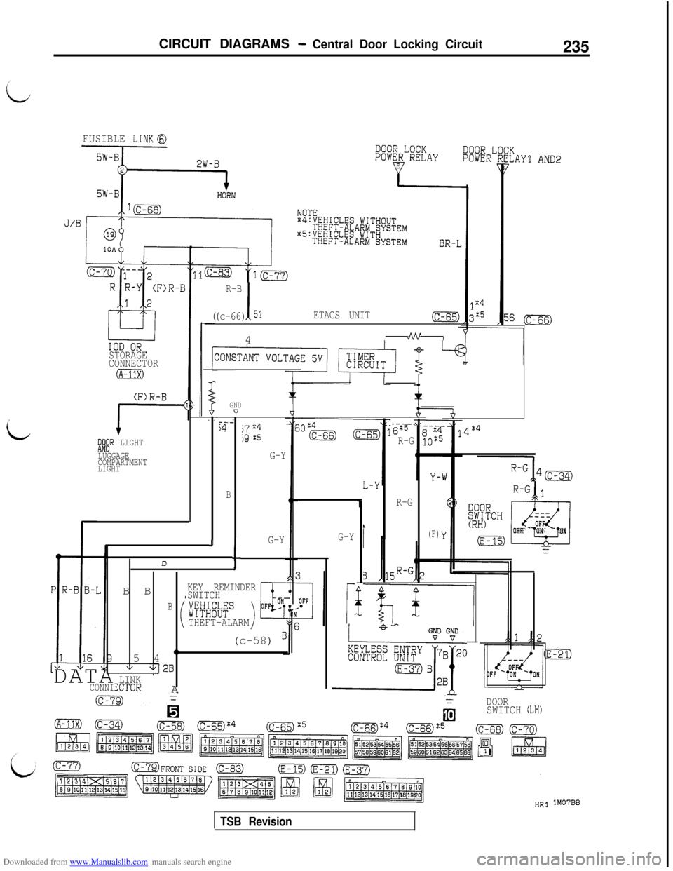
Downloaded from www.Manualslib.com manuals search engine CIRCUIT DIAGRAMS - Central Door Locking Circuit235
FUSIBLE LINK0
R-B
1(c-66) 51ETACS UNIT(c-65)4
Inhn""YI
STORAGE
CONNECTOR
(A-11X)
(F>R-B
;I;" LIGHT
LUGGAGE
COMPARTMENT
LIGHT
GNDn
i
--254j7:4jg $5
G-Y
B
(F)
----_6:5
R-G
R-G
4:4
R-G 1
ir
---OFFOFF - ON - ON
1
G-Y.J
I
G-YD
II=
GND GND
kxmJ77~oB B
KEY REMINDER
SWITCH
Bw&BSTHEFT-ALARM
(c-58) B5 4
"v vj2B
LINKXTORA DATACONNI
DOORSWITCH (LH)
lM07BB
TSB Revision
Page 240 of 738
Downloaded from www.Manualslib.com manuals search engine 238CIRCUIT .DIAGRAMS - Central Door Locking Circuit
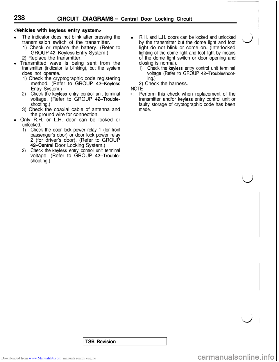
The indicator does not blink after pressing thetransmission switch of the transmitter.
1) Check or replace the battery. (Refer to
GROUP
42-Keyless Entry System.)
2) Replace the transmitter.
l Transmitted wave is being sent from thel
R.H. and L.H. doors can be locked and unlocked
by the transmitter but the dome light and footlight do not blink or come on. (Interlocked
lighting of the dome light and foot light by means
of the dome light switch or door opening and
closing is normal).
transmitter (indicator is blinking), but the system
does not operate.1) Check the cryptographic code registering
method. (Refer to GROUP
42-Keyless
Entry System.)
2)Check the keyless entry control unit terminalvoltage. (Refer to GROUP
42-Trouble-
shooting.)3) Check the coaxial cable of antenna and
the ground wire for connection.
l Only R.H. or L.H. door can be locked or
unlocked.
1)Check the door lock power relay 1 (for front
passenger’s door) or door lock power relay2 (for driver’s door). (Refer to GROUP
42-Central Door Locking System.)
2)Check the keyless entry control unit terminalvoltage. (Refer to GROUP
42-Trouble-
shooting.)
1)Check the keyless entry control unit terminal
voltage (Refer to GROUP
42-Troubleshoot-
ing.)2) Check the harness.
NOTE
l :Perform this check when replacement of the
transmitter and/or
keyless entry control unit or
faulty storage of cryptographic code has been
made.
\
Ilj
‘d I
1 TSB Revision
Page 278 of 738
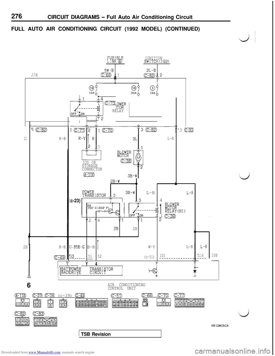
Downloaded from www.Manualslib.com manuals search engine 276CIRCUIT DIAGRAMS - Full Auto Air Conditioning Circuit
FULL AUTO AIR CONDITIONING CIRCUIT (1992 MODEL) (CONTINUED)
21
L,E
nfR”6”bIGNITIONSWITCH(IG2)
5W-B2L-B
J/B
(c-68) ,,l(c-82),, 2IA\j(c-82)
R-B
2BR-B
(c-49)
I%#~”Q;FRELAY
- I
ii
L-R
c-23)
PI%F%”
IOD OR(c-38)
STORAGE
CONNECTOR
(A-11X)
:;;&sToR [r;;l, L-R
\,OFF-,;ON"2 "4
"1"1
282B
).85B-G B-RIW-Y
535152------_ __(c-51)
-iY41
/ pm%/1 ED% E%WTCR 14
'3 (c-83)
1
k?!ERRELAYCHI)
2m
L-R
101--------------.116.---108
16/I
AIR CONDITIONING
CONTROL UNIT
(A-11X)(c-23) (c-38) (c-39) cm9(c-51)(c-68) (c-70) (c-77)
HR12M05CA
L/
1 TSB Revision
Page 286 of 738
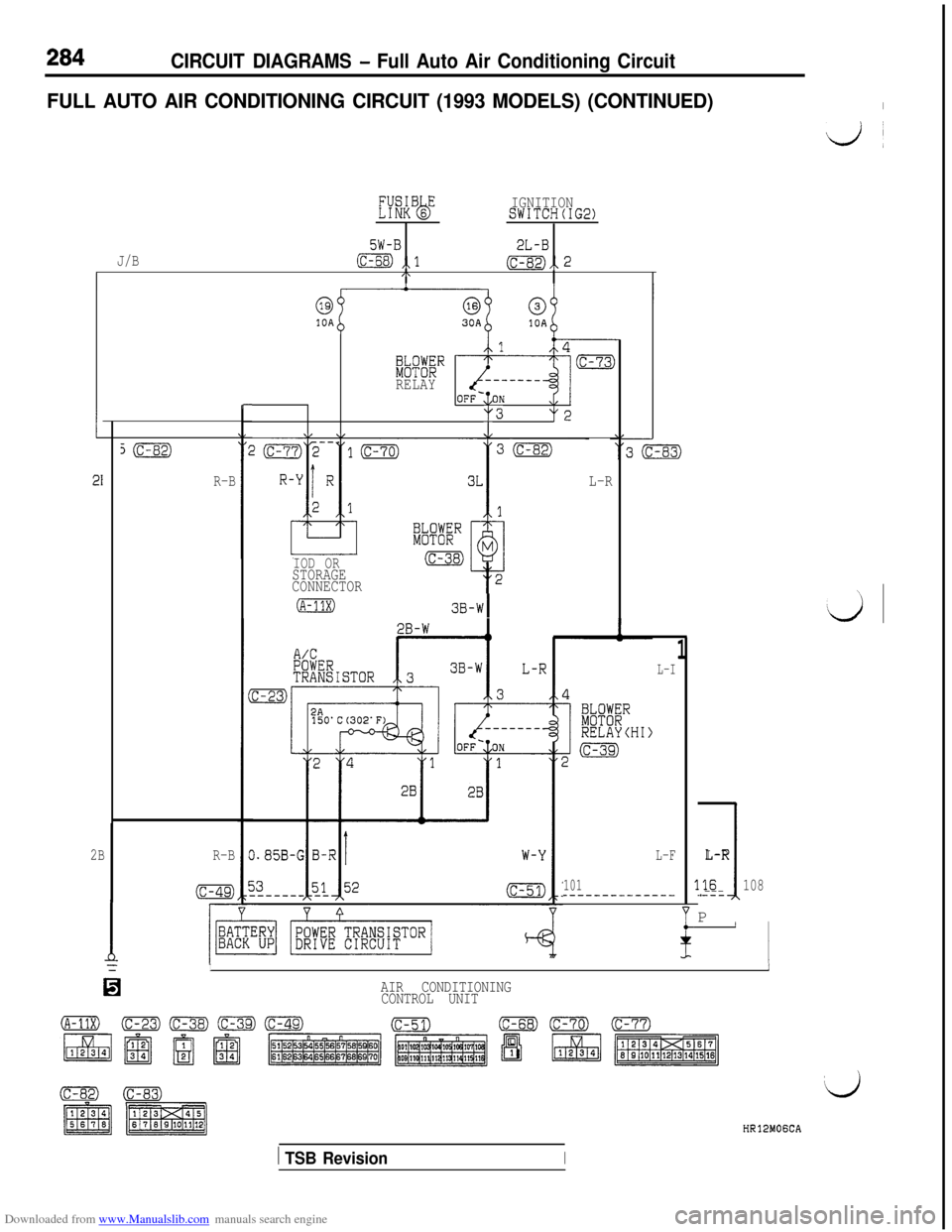
Downloaded from www.Manualslib.com manuals search engine 284CIRCUIT DIAGRAMS - Full Auto Air Conditioning Circuit
FULL AUTO AIR CONDITIONING CIRCUIT (1993 MODELS) (CONTINUED)I
Ij~
KkBsEbIGNITIONSWITCH(IG2)
5W-B2L-BJ/Bm ,,l(c-82),, 2I\
1
21
s(c-82)
R-B
2BR-B
(c-49)
r-
kK%”RELAY
y3y2
v \/.J/
IOD ORSTORAGE
CONNECTORL-R
(A-11X)3B-WI
L-I
L-F
101----_-_--__---
1
1
L-R
3.16108.---P
II
/YII
IaAIR CONDITIONING
CONTROL UNIT
HR12MOGCA
1 TSB RevisionI
Page 294 of 738
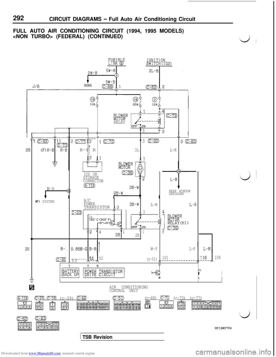
Downloaded from www.Manualslib.com manuals search engine 292CIRCUIT DIAGRAMS - Full Auto Air Conditioning Circuit
FULL AUTO AIR CONDITIONING CIRCUIT (1994, 1995 MODELS)
$d I
213R-:W-YL-F
(C-4E53 115152---------(c-51)101108m
tI
nL
0
I
AIR CONDITIONING
CONTROL UNIT
(A-11X)(C-23) (c-38) (c-39) e=m(c-51)(c-68) (c-70) (c-73) (c-77)
IOD OR34
STORAGE
CONNECTORL-R
R-B(A-11X)--I-REAR WINDOW
DEFOGGER
MFI SYSTEMA/C
POWER
TRANSISTOR ,.33B-W
L-RL-E
c-23)------,<,\ 3
2A-7
-----__-)I)
\/ v\,OFF-,;ON
"2 "4"128" 12B(C$4
imER.(c-73)
RELAYOFF-,;ON
"3
/v
z(c-77)2-- l(c-70)"3 (c-82)3mR-Y R
I3LL-R
,,2 ,,l,l
L“F
28
HR12M07CA
1 TSB Revision
Page 302 of 738
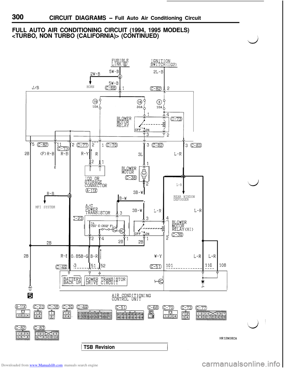
Downloaded from www.Manualslib.com manuals search engine 300CIRCUIT DIAGRAMS - Full Auto Air Conditioning Circuit
FULL AUTO AIR CONDITIONING CIRCUIT (1994, 1995 MODELS)
i
2W-B2L-B
15W-BJ/BHORN(c-68) ,,lI(c-82),, 2,\bI
\/
"5 (c-82)"
28(F)R-B
E
R-B
MFI SYSTEM
02B
28R-E
(c-49:
I15
13I, 151 52.-----_ __(c-51)
v 0--
1 /%Z”BpYI (EKE RfiF8iaToRj
T
\I \IJV
‘20 2-- 10D'3 (c-83)
jL-R
,,2 ,,l\ /\
IOD ORSTORAGECONNECTORL-R
(A-11X)3B-WI
,2B-W1
A/CPOWERTRANSISTOR,,3
m-------.-2A------__1\I \,\/OFF-,;ON"2 "428"1"12B
W-Y
TREAR WINDOW
DEFOGGER
L-R
4
I
BkPKRRELAYCHI)
2m
0
L-RL-R
101116108------___------ -___
Lj
AIR CONDITIONINGCONTROL UNIT
HR12MOECA
1 TSB Revision
Page 310 of 738
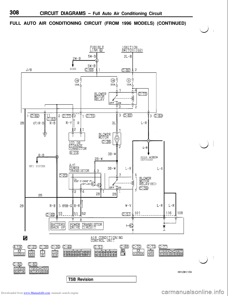
Downloaded from www.Manualslib.com manuals search engine CIRCUIT DIAGRAMS - Full Auto Air Conditioning CircuitFULL AUTO AIR CONDITIONING CIRCUIT (FROM 1996 MODELS) (CONTINUED)
\
‘d ~
2W-B2L-B
5W-B
J/0HORN(c-68) ,,l(c-82),, 2
R-B
MFI SYSTEM
2B
R-E
1
6310A
4
iFBR(c-73)
RELAY
\,&\/T- \I
J2(c-77)2-- 10"3 (c-83)
IR-Y Ri,2 ,,lI\ /\
IOD ORSTORAGECONNECTOR
(A-11X)
L-R
t
34
L-R
A/CPOWERTRANSISTOR ,.33B-WL-R
c-23),\ 3I\2A- - - - - - - -,
\,\/OFF-:,ON
"2 "4"12B" 12B
).85B-G B-RW-Y
(c-51)
REAR WiNDOWDEFOGGER
L-K
4
I
k%"RELAYCHI)
,m
L-RL-R
101116108-
AIR CONDITIONINGCONTROL UNIT
(c-se)0HRlPMllCA
1 TSB Revision
Page 358 of 738
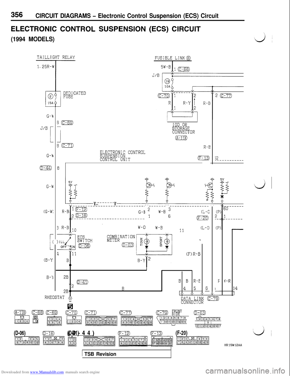
Downloaded from www.Manualslib.com manuals search engine 356CIRCUIT DIAGRAMS - Electronic Control Suspension (ECS) Circuit
ELECTRONIC CONTROL SUSPENSION (ECS) CIRCUIT
(1994 MODELS)
FUSIBLE [email protected]
G-h
J/BL
G-k
s(c-69)-
1
80
(D-44)8
G-W
(G-W:
3R-B10 l------l 1o W-B 11 (L-0W-O
L
(
(B-Y
B-k
IIIOD ORSTORAGECONNECTOR
(A-11X)
R-B
ELECTRONIC CONTROLSUSPENSIONCONTROL UNIT(F-;2---------
4
-
(P2_-.
(P
F
\-
3
----------------------------- ------- ----------------
R-B ‘(F-12)
p(D-16)G-B 2
I-----------:----------------
W-B 3(L-C1 6(F-20)
I
2B
“2 ma
B B R-E
2BtB4 5A A A
V-R
6-14
1h
RHEOSTATA=DATA LINK (c-7CONNECTOR
(A-11X)(c-70)(D-03)11213/41516/716n
9 ~10~11~12~13j14/15~16112]31415161716
u1 2 110~11/12/13/~4~15)16~17
(D-06)(D-16)
(D-41)(D-44)(F-m(F-20)
HR15M12AA
1 TSB Revision
Page 362 of 738
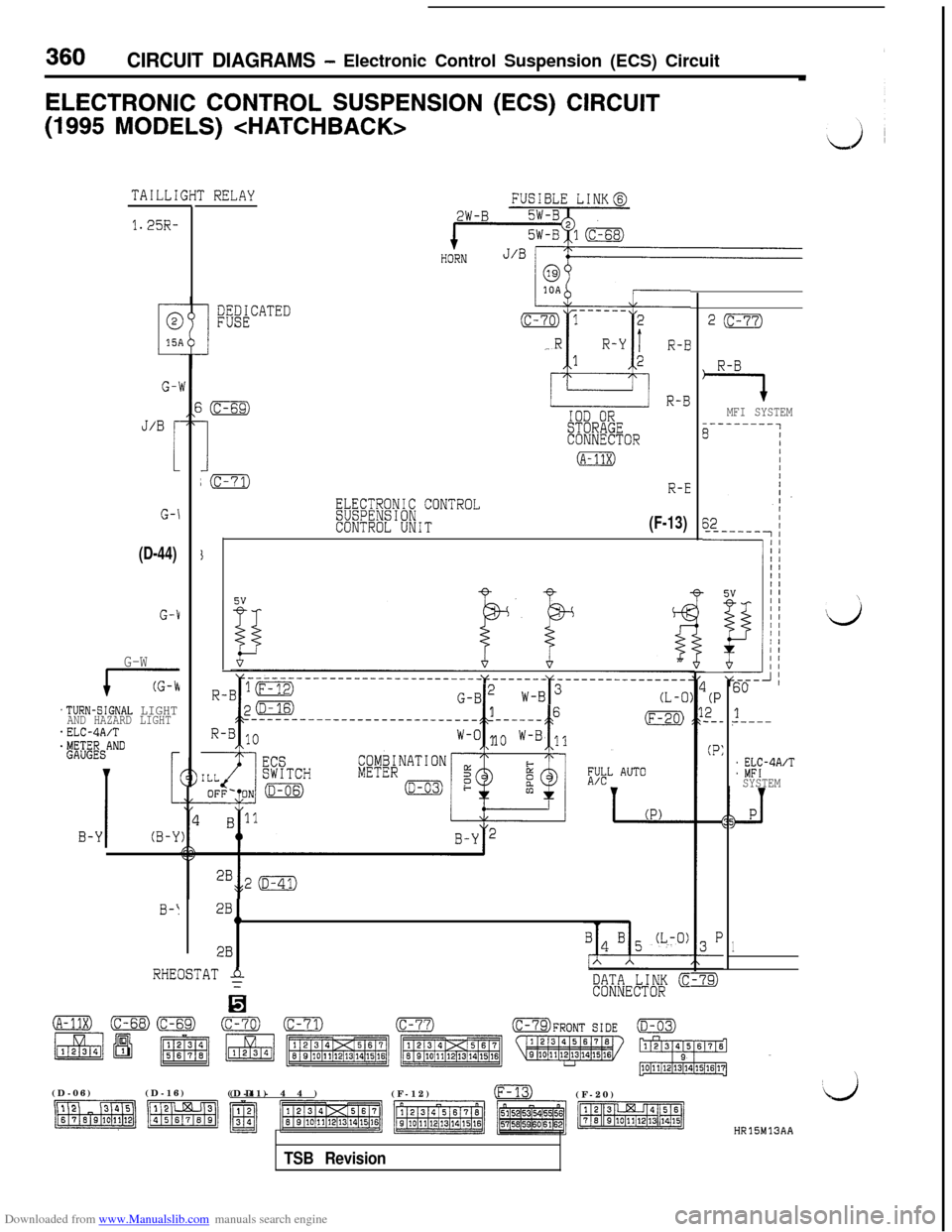
Downloaded from www.Manualslib.com manuals search engine 360CIRCUIT DIAGRAMS - Electronic Control Suspension (ECS) Circuit
ELECTRONIC CONTROL SUSPENSION (ECS) CIRCUIT(1995
MODELS)
TAILLI
1.25R-
G-1
J/B r
1
G-\
(D-44)
G-1
G-W
17
.TURN-SIGNAL LIGHTAND HAZARD LIGHT*ELC-4A/T$&ANDr
I
1
B-Y(B-Y
0-I
r RELAY
mACATED
i(c-69)
I
IOD ORSTORAGECONNECTOR
(A-11x)
;(c-71)R-E
ELECTRONIC CONTROLSUSPENSIONCONTROL UNIT(F-13)
G-B2 w
c t
16---------------------------- ---___(F-20)
W-O 1o W-B 11
2B1h
2B
RHEOSTAT $
H
DATA LINK cCONNECTOR
2(c-77)
R-B
7MFI SYSTEM
(P2_-_
(P:
60
1?-----
: %?-4A’TSYSTEM
1
\(D-06)(D-16)
(D-41)(D-44)
(F-12)
m(F-20)
HR15M13AA
TSB Revision
Page 366 of 738
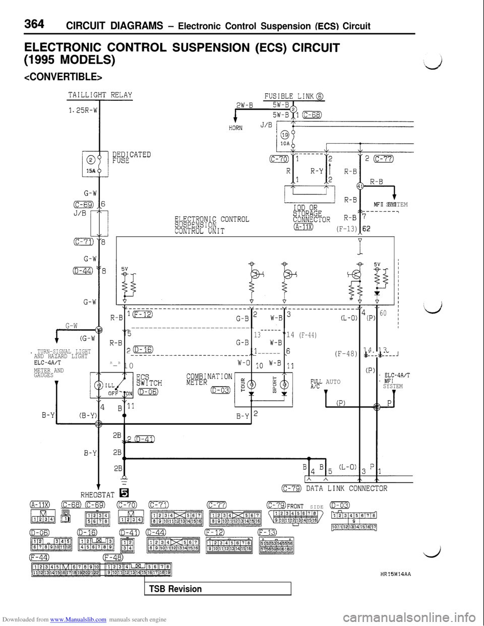
Downloaded from www.Manualslib.com manuals search engine 364CIRCUIT DIAGRAMS - Electronic Control Suspension (ECS) Circuit
ELECTRONIC CONTROL SUSPENSION (ECS) CIRCUIT
(1995 MODELS)
1.25R-\i
i
@
15A
G-V
(c-69)
J/B
i
(c-71)
G-h
(D-44)
G-h
G-W
i---z
. TURN-SIGNAL LIGHTAND HAZARD LIGHTELC4A/TMETER AND
GAUGESr
FUSIBLE LINK@
2W-B
ELECTRONIC CONTROLSUSPENSIONCONTROL UNIT
R-B
R-B41
R-BIOD OR
/I
MFI SYSTEM
STORAGE-------7
CONNECTORR-B 7
(A-11X)(F-13) 62
4
-__________-_-__----------
R-B ‘m
---------------------------- -----_‘313“14
R-BG-BW-Bp(D--__-----------------________,1
------,6R
-B
10
W-O 1o W-B 11
COMBINATION/\
METER
B '110B-Y 2
__-------------
(L-0) 4cP)60
(F-44)
14 13(F-48) t+--:+---J
(P)
;$L AUTO1 K-4A/TSYSTEM
(P)
(c-79) DATA LINK CONNECTOR
(A-11X) cm(m) (c-70) (c-71)(c-77)OFRONT SIDE (D-03)
HR15M14AA
Lj
TSB Revision