charging MITSUBISHI 3000GT 1992 2.G Owner's Guide
[x] Cancel search | Manufacturer: MITSUBISHI, Model Year: 1992, Model line: 3000GT, Model: MITSUBISHI 3000GT 1992 2.GPages: 738, PDF Size: 35.06 MB
Page 459 of 738

Downloaded from www.Manualslib.com manuals search engine ENGINE ELECTRICAL - Charging System16-13DISASSEMBLY AND REASSEMBLY
i(Up to 1995 models)23I
LDisassembly steps
4A,1. Generator pulley.A+ 2. Rotor assembly3.Rear bearing4.Bearing retainer5.Front bearing6.Front bracket4B,7.Stator8. Insulator
9. Plate
10. Reaulator and brush holder
11.
Slinlger12. Rectifier13. Brush14. Brush spring
15. Rear bracket
4B,27EL0104
1 TSB Revision
Page 460 of 738
Downloaded from www.Manualslib.com manuals search engine 16-14ENGINE ELECTRICAL - Charging System
(From 1996 models)
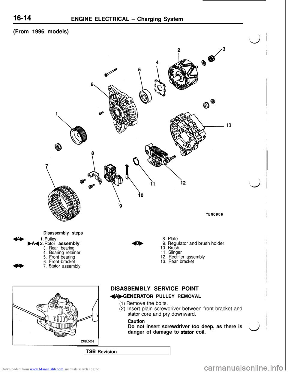
Disassembly steps
+A,,A+ :: ~%? assembly3.Rear bearing4.Bearing retainer5.Front bearing6.Front bracket
45,7.Stator assembly
13
TEN0906
8. Plate9. Regulator and brush holder
10. Brush
11. Slinger
12. Rectifier assembly
13. Rear bracket
IDISASSEMBLY SERVICE POINT
dAbGENERATOR PULLEY REMOVAL
(1) Remove the bolts.
(2) Insert plain screwdriver between front bracket and
stator core and pry downward.
Caution
Do not insert screwdriver too deep, as there is
danger of damage to
stator coil.
TSB Revision
Page 461 of 738
Downloaded from www.Manualslib.com manuals search engine ENGINE ELECTRICAL - Charging System16-15
WireZ6EN087!(3) Clamp the rotor in a vise with soft jaws.
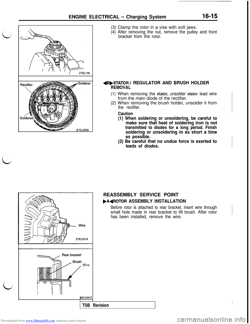
(4) After removing the nut, remove the pulley and front
bracket from the rotor.
AB,STATOR / REGULATOR AND BRUSH HOLDER
REMOVAL
(1) When removing the stator, unsolder stator lead wirefrom the main diode of the rectifier.
(2) When removing the brush holder, unsolder it from
the rectifier.
Caution
(1) When soldering or unsoldering, be careful to
make sure that heat of soldering iron is not
transmitted to diodes for a long period. Finish
soldering or unsoldering in as short a time
as possible.
(2) Be careful that no undue force is exerted to
leads of diodes.REASSEMBLY SERVICE POINT
FAdROTOR ASSEMBLY INSTALLATION
Before rotor is attached to rear bracket, insert wire through
small hole made in rear bracket to lift brush. After rotor
has been installed, remove the wire.
3
TSB RevisionI
I
Page 462 of 738
Downloaded from www.Manualslib.com manuals search engine ENGINE ELECTRICAL - Charging System
h\Z3ELOlO
\23ELOllINSPECTION
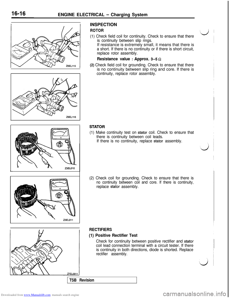
ROTOR
(1) Check field coil for continuity. Check to ensure that there
is continuity between slip rings.If resistance is extremely small, it means that there is
a short. If there is no continuity or if there is short circuit,
replace rotor assembly.
Resistance value : Approx. 3-5 Q
(2) Check field coil for grounding. Check to ensure that thereis no continuity between slip ring and core. If there is
continuity, replace rotor assembly.
STATOR
(1) Make continuity test on stator coil. Check to ensure that
there is continuity between coil leads.
If there is no continuity, replace
stator assembly.
(2) Check coil for grounding. Check to ensure that there is
no continuity between coil and core. If there is continuity,
replace stator assembly.
RECTIFIERS
(1) Positive Rectifier Test
Check for continuity between positive rectifier and stator
coil lead connection terminal with a circuit tester. If there
is continuity in both directions, diode is shorted. Replace
rectifier assembly.
TSB Revision
Page 463 of 738
Downloaded from www.Manualslib.com manuals search engine ENGINE ELECTRICAL - Charging System16-17
Limit line
WELO
,Soldered
27EL0014
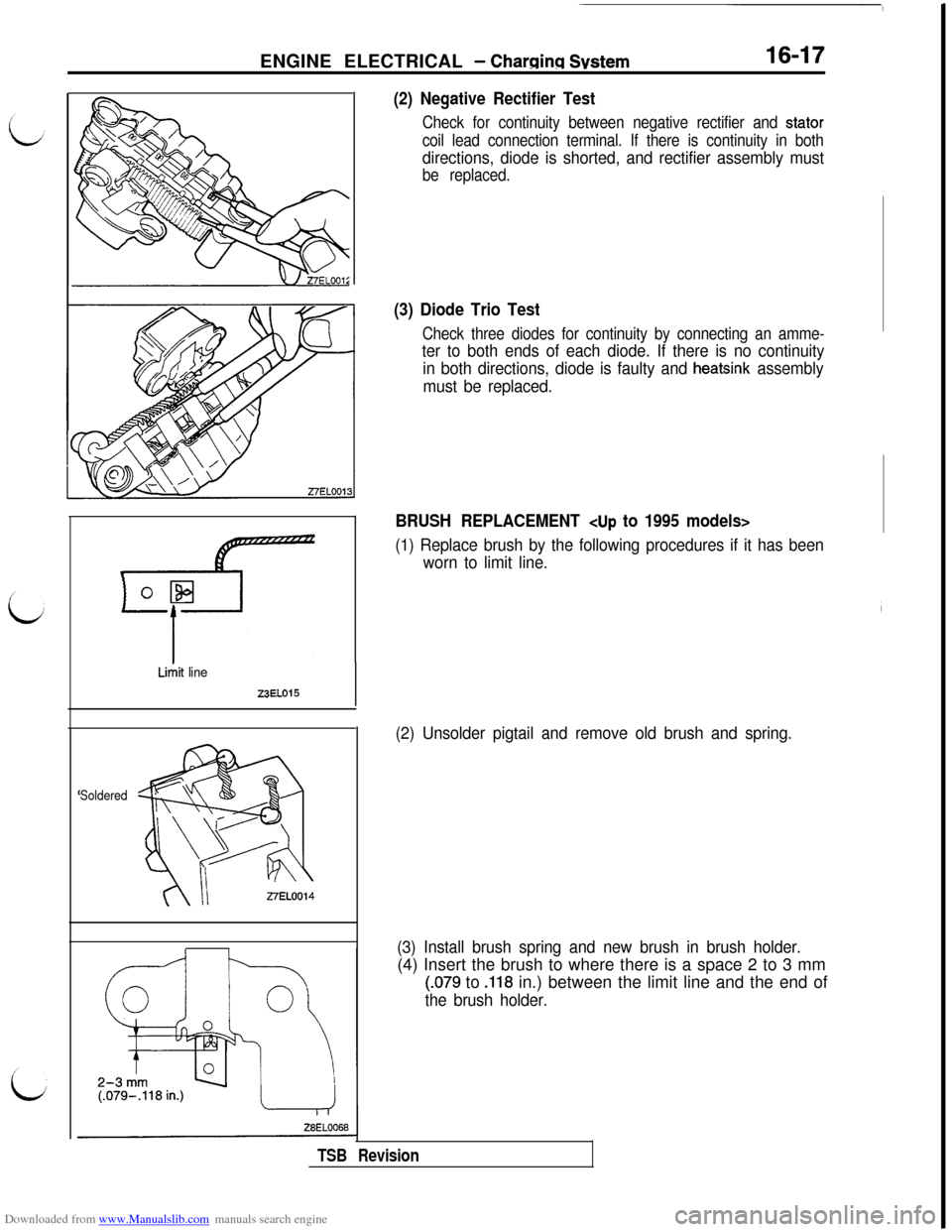
(2) Negative Rectifier Test
Check for continuity between negative rectifier and stator
coil lead connection terminal. If there is continuity in both
directions, diode is shorted, and rectifier assembly must
be replaced.
(3) Diode Trio Test
Check three diodes for continuity by connecting an amme-
ter to both ends of each diode. If there is no continuity
in both directions, diode is faulty and
heatsink assembly
must be replaced.
BRUSH REPLACEMENT
(1) Replace brush by the following procedures if it has been
worn to limit line.
(2) Unsolder pigtail and remove old brush and spring.
(3) Install brush spring and new brush in brush holder.(4) Insert the brush to where there is a space 2 to 3 mm
(.079 to .118 in.) between the limit line and the end of
the brush holder.
TSB Revision
Page 464 of 738
Downloaded from www.Manualslib.com manuals search engine 16-18ENGINE ELECTRICAL - Charging System
Soldered
Limit line
&
mm
o L%4
-if
T
9EN0192
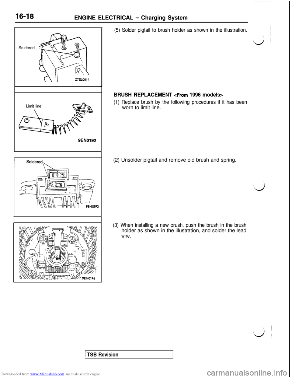
(5) Solder pigtail to brush holder as shown in the illustration.
BRUSH REPLACEMENT
(1) Replace brush by the following procedures if it has beenworn to limit line.
(2) Unsolder pigtail and remove old brush and spring.
(3) When installing a new brush, push the brush in the brushholder as shown in the illustration, and solder the lead
wire.
1 TSB Revision
Page 479 of 738
Downloaded from www.Manualslib.com manuals search engine ENGINE ELECTRICAL - Ignition Svstem
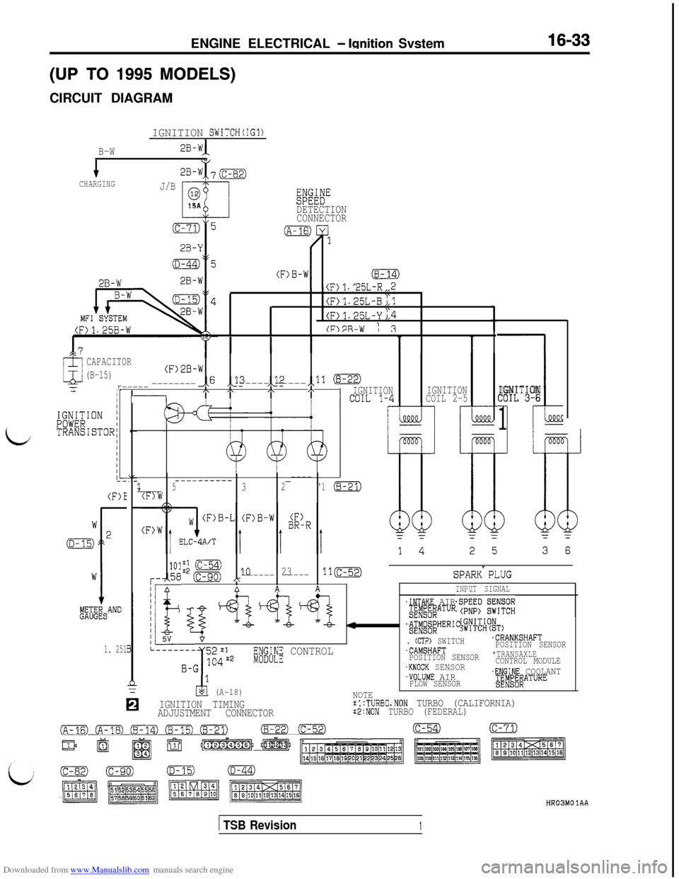
(UP TO 1995 MODELS)CIRCUIT DIAGRAM
IGNITION SWITCH(IG1)
B-W
1CHARGING33-W 70
J/B0
t15A
(c-71)5
2B-Y
2B-W
WEDETECTION
CONNECTOR
\I/1. c5L-R,,2
(F)1.25L-B;,lI'(F>1.25L-Y J,4
(FlPR-W : 3
CAPACITOR
(B-15)(F)2B-W
,x6 ,J3,_12=r------------------ -----,,ll (B-22)
iI -,\ I\,\,\IGNITION' ""TL 1-4IGNITION
COIL 2-5
i
IGNITION
COIL 3-6
1
(F)E_________-----------_----1532'1(8-21)(F)W
101;; (C-54)
r-,58 (c-90) A
1o23-----------ll(c-52)
I/ AAAA
SPARK"PLUG
INPUT SIGNAL
&i&AND
1. 251
!I
~~$yqppQ.INTAKE AIRgE;g;EATUREsiKz&G
'&$AT~~;HER'C
k-_""_---- 52~1. (CTP) SWITCH.CRANKSHAFT
3.CAMSHAFTPOSITION SENSOR
B-G 104g2
I
if;INE CONTROLPOSITION SENSOR*TRANSAXLE
.KNOCK SENSORCONTROL MODULE
2 (A-18)
.VOLUME AIR.ENGINE COOLANT
FLOW SENSOR$~~~~~ATURE
0
NOTEIGNITION TIMING:l:TURBO,NON TURBO (CALIFORNIA)ADJUSTMENT CONNECTORx2:NON TURBO (FEDERAL)
FE) CFm) (B-14) Em3 EFZTJ(B-22)-(c-54)(c-71)
/$J$mb @f-@
ok4 Oh,
( TSB Revision1
HR03MO 1AA
Page 480 of 738
Downloaded from www.Manualslib.com manuals search engine 16-34ENGINE ELECTRICAL - Ignition System
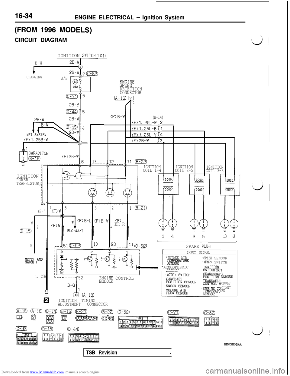
(FROM 1996 MODELS)CIRCUIT DIAGRAM
IGNITION SWITCH(IG1)
B-W
iCHARGINGJ/B
Eiwi"
/DETECTION
(c-73)“5CONNECTOR
2B-Y
(D-44)“5
2B-W-I
2B-W
MFILS - --
(F>B-W(B-14)
(F)l. 25L-R,,2
(F)1.25L-B;,l
(F>1.25L-Yj,4
(F>2B-W ),3-
.
13,<2------ ---__,,11 (8-22),\,\IGNITIONCOIL l-4IGNITION
COIL 2-5IGNITIONCOIL 3-6-4III(r
,cl
(F>2B-W
IGNITION /POWER
TRANSISTOR;
I
(F)'
\I\/,I--------------
-----
-----
I5(F)W321m
BR-RW
(D-15)2
W
METE1GAUGI*AND)3 6
\-I
G9SPARK PLU4
9 41INPUT SIGNAL
*INTAKE AIRg;#j#ATURE
"-b- bkl *ATMOSPHERIC9FLTcno
-SPEED SENSOR.(PNP) SWITCH.-.-..
, 4””
---- 521ENG:h!E CONTROLMODI
TENSOR
ODULE
OLANT
RE
IGNITION TIMING
ADJUSTMENT CONNECTOR
1. 25
HR03M02AA
TSB Revision1
Page 497 of 738
Downloaded from www.Manualslib.com manuals search engine 54-1
CHASSIS
ELECTRICAL
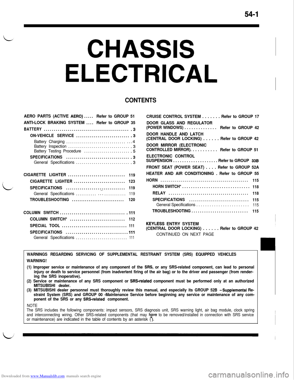
CONTENTS
AERO PARTS (ACTIVE AERO).....Refer to GROUP 51
ANTI-LOCK BRAKING SYSTEM....
Refer to GROUP 35
BATTERY...........................................-3
ON-VEHICLE SERVICE............................3
Battery Charging.................................4Battery Inspection................................3Battery Testing Procedure........................5
SPECIFICATIONS................................-3
General Specifications............................3
CIGARETTE LIGHTER.............................119
CIGARETTE LIGHTER..........................123
SPECIFICATIONS..............................
119
General Specifications............I...........119
TROUBLESHOOTING............................120
COLUMN SWITCH.................................
.lll
COLUMN SWITCH*............................112
SPECIAL TOOL.................................111
SPECIFICATIONS...............................111
General Specifications..........................111
CRUISE CONTROL SYSTEM . . . . . . . Refer to GROUP 17
DOOR GLASS AND REGULATOR
(POWER WINDOWS) . . . . . . . . . . . . . .Refer to GROUP 42
DOOR HANDLE AND LATCH
(CENTRAL DOOR LOCKING) . . . . . . Refer to GROUP 42
DOOR MIRROR (ELECTRONIC
CONTROLLED MIRROR). . . . . . . . . . .Refer to GROUP 51
ELECTRONIC CONTROL
SUSPENSION . . . . . . . . . . . . . . . . . . . . Refer to GROUP
338
FRONT SEAT (POWER SEAT) . . . . Refer to GROUP 52A
HEATER AND AIR CONDITIONING . Refer to GROUP 55
HORN. . . . . . . . . . . . . . . . . . . . . . . . . . . . . . . . . . . . . . . . . . . .
115
HORN SWITCH* . . . . . . . . . . . . . . . . . . . . . . . . . . . . . . .118
RELAY. . . . . . . . . . . . . . . . . . . . . . . . . . . . . . . . . . . . . . . .
118
SPECIFICATIONS. . . . . . . . . . . . . . . . . . . . . . . . . . . . . .
115
General Specifications . . . . . . . . . . . . . . . . . . . . . . . .115
TROUBLESHOOTING . . . . . . . . . . . . . . . . . . . . . . . . . . .115
KEYLESS ENTRY SYSTEM
(CENTRAL DOOR LOCKING) . . . . . . Refer to GROUP 42
CONTINUED ON NEXT PAGE
WARNINGS REGARDING SERVICING OF SUPPLEMENTAL RESTRAINT SYSTEM (SRS) EQUIPPED VEHICLES
WARNING!
(1) Improper service or maintenance of any component of the
SRS, or any SRS-related component, can lead to personal
injury or death to service personnel (from inadvertent firing of the air bag) or to the driver and passenger (from render-
ing the SRS inoperative).
(2) Service or maintenance of any SRS component or
SRS-related component must be performed only at an authorized
MITSUBISHI dealer.
(3)MITSUBISHI dealer personnel must thoroughly review this manual, and especially its GROUP 52B
TSupplemental Re-
straint System (SRS) and GROUP 00 -Maintenance Service before beginning any service or maintenance of any com-
ponent of the SRS or any
SRS-related component.
NOTE
The SRS includes the following components: impact sensors, SRS diagnosis unit, SRS warning light, air bag module, clock spring
and interconnecting wiring. Other SRS-related components (that may
h,a”” to be removed/installed in connection with SRS serviceor maintenance) are indicated in the table of contents by an asterisk ( ).
Page 499 of 738
Downloaded from www.Manualslib.com manuals search engine CHASSIS ELECTRICAL - Battery54-3
BATTERY
LSPECIFICATIONSGENERAL SPECIFICATIONS
ItemsUp to 1993 modelsFrom 1994 models
Type75D26R-MF75D23R-MF
Ampere hours
(5HR) Ah5252
Cranking rating [at -18°C (O’F)] A490520
Reserve capacity min.123118
NOTES
1.CRANKING RATING is the current a battery can deliver for 30 seconds and maintain a terminal voltage of
7.2 volts or greater at a specified temperature.
2.RESERVE CAPACITY RATING is the amount of time a battery can deliver 25A and maintain a minimum terminal
voltage of 10.5 at
27% (80°F).
L
16FO123
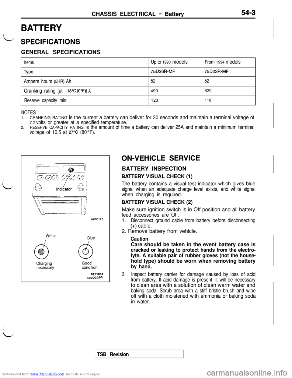
White
Blue
ChargingGood
necessaryconditionON-VEHICLE
SERVICE
BATTERY INSPECTION
BAlTERY VISUAL CHECK (1)
The battery contains a visual test indicator which gives blue
signal when an adequate charge level exists, and white signal
when charging is required.
BAlTERY VISUAL CHECK (2)
Make sure ignition switch is in Off position and all battery
feed accessories are Off.
1.Disconnect ground cable from battery before disconnecting
(+) cable.
2. Remove battery from vehicle.
CautionCare should be taken in the event battery case is
cracked or leaking to protect hands from the electro-
lyte. A suitable pair of rubber gloves (not the house-hold type) should be worn when removing battery
by hand.
3.Inspect battery carrier for damage caused by loss of acid
from battery. If acid damage is present, it will be necessaryto clean area with a solution of clean warm water and
baking soda. Scrub area with a stiff bristle brush and wipe
off with a cloth moistened with ammonia or baking soda
in water.
TSB Revision