turn signal MITSUBISHI 3000GT 1992 2.G Repair Manual
[x] Cancel search | Manufacturer: MITSUBISHI, Model Year: 1992, Model line: 3000GT, Model: MITSUBISHI 3000GT 1992 2.GPages: 738, PDF Size: 35.06 MB
Page 587 of 738
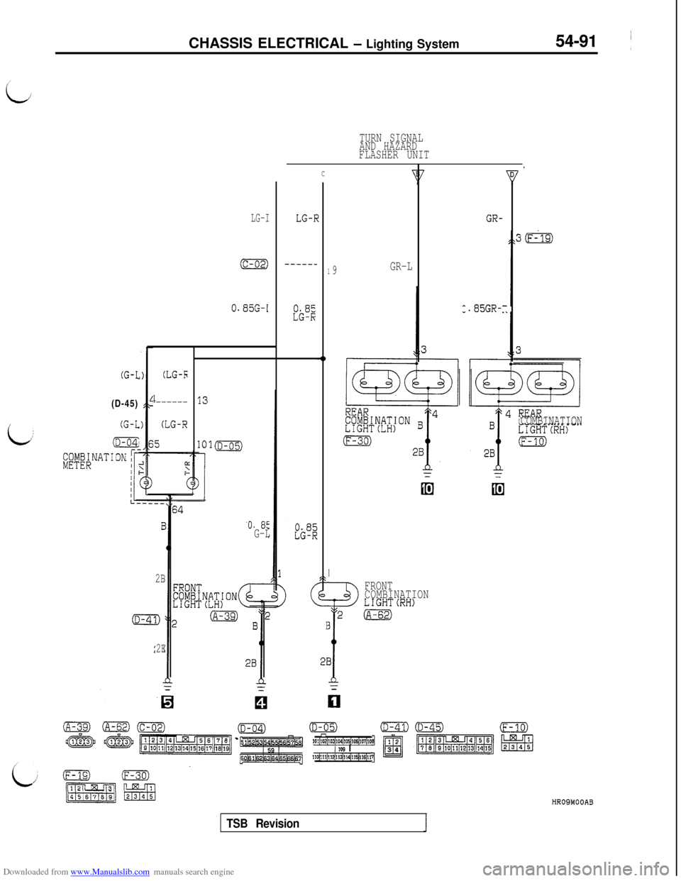
Downloaded from www.Manualslib.com manuals search engine CHASSIS ELECTRICAL - Lighting System54-91 ~
TURN SIGNAL
AND HAZARD
FLASHER UNIT
LG-I
9GR-L
GR-
.85GR-
C
LG-F?
-----_
,Ii;";,
1
-0
1
FRONT
COMBINATION
LIGHT(RH)2(A-62)
B
!
28
-z
(c-02)
0.85G-I
COMBINATION
(G-l(D-45)(G-L
iD-04:
(LG-5
i------
(LG-R
'0. 85G-L
2B
2E
El
(D-05)(D-41)n1P1~102~103~104~1os~1~~107~lffl1 21 IW I?$a34110(111~112j11~114$15~116~1,
HR09MOOA3
TSB Revision
Page 588 of 738
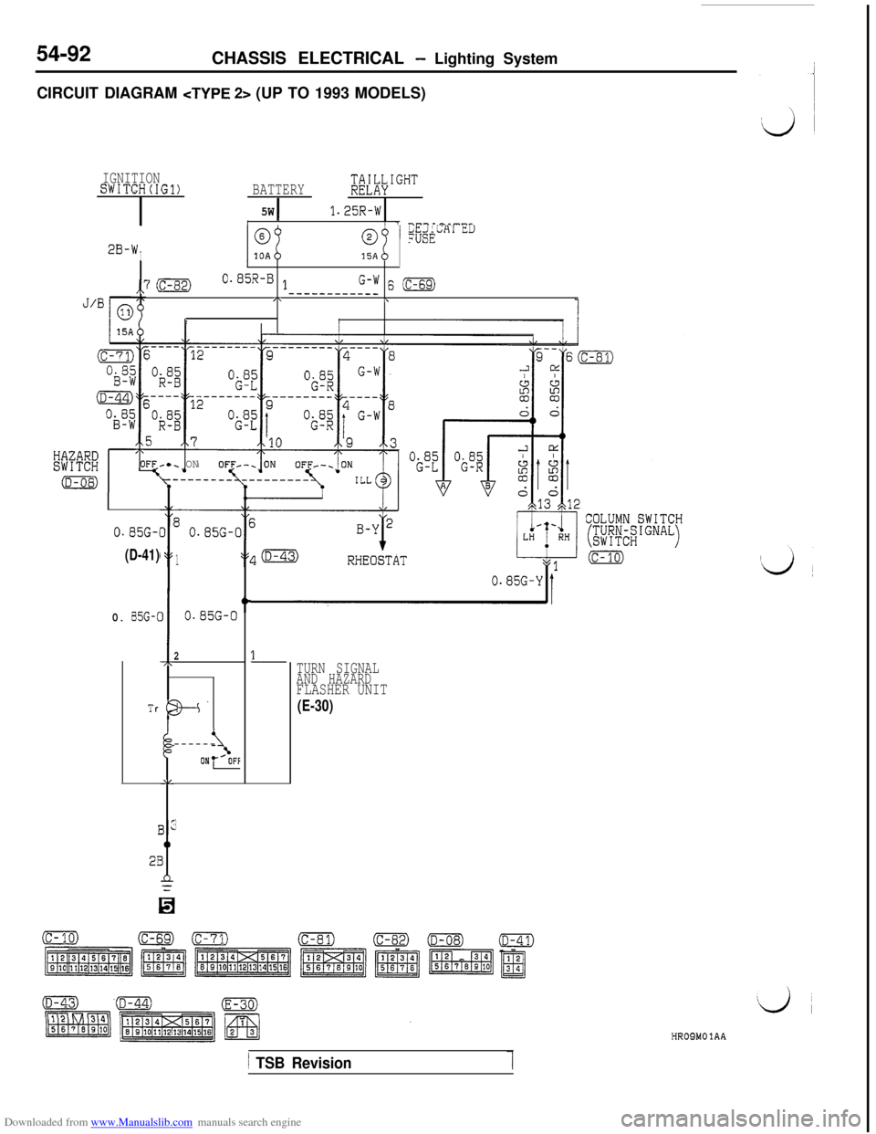
Downloaded from www.Manualslib.com manuals search engine 54-92CHASSIS ELECTRICAL - Lighting System
CIRCUIT DIAGRAM
IGNITIONSWITCH(IG1)BATTERY$E"Lh\IGHT
5W1.25R-WI/ 1 -.---^^^^r
2B-WI
@@!p&LHl LLI
10A15AI
,,7 (c-82)0.05R-0 1G-W 6 (c-69)------__--__J/BI\\
rI
0.85G-1
(D-41)
,\OFFc.. ON
0. 85G-C
Tr
I
2I
II
I
-7r
I;
AL
3:
0
3
n=
3
80.85G-C
1
0.85G-0
2
t
B--’
\------ON-
0.85G-Y
1TURN SIGNAL
AND HAZARD
FLASHER UNIT
(E-30)
HROSMOlAA
1 TSB Revision
Page 590 of 738
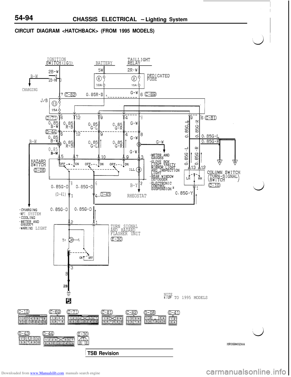
Downloaded from www.Manualslib.com manuals search engine 54-94CHASSIS ELECTRICAL - Lighting System
CIRCUIT DIAGRAM
IGNITIONSWITCH(IG1)BATTERY;di\IGHT
28-W2R-W
B-W2B-W6 00l;akCATED15A
CHARGING
,,7(c-82)0.85R-B1G-WS(c-69)-----------_/\J’BI no
1.CHARGING.MFI SYSTEM'COOLING$F!;E$qAND
.WARNIiG LIGHT
I,,
0.85G-C810.85G-06B-Y 2
(D-41)::q (D-43)1
‘$1RHEOSTAT
0.85G-00.85G-0
Ii
I \"w\/\/b/---- -------- --------a‘% ‘52‘3---_‘2'8"9-- '6m2 DiI I2
si
d: O.BSG-L
B-W0.85G-R
0.852 L1:
B-W/ I
2B
TURN SIGNAL
AND HAZARD
FLASHER UNIT
:E-30)
NOTE::UP TO 1995 MODELS
dHROSM02AA
/ TSB Revision
Page 592 of 738
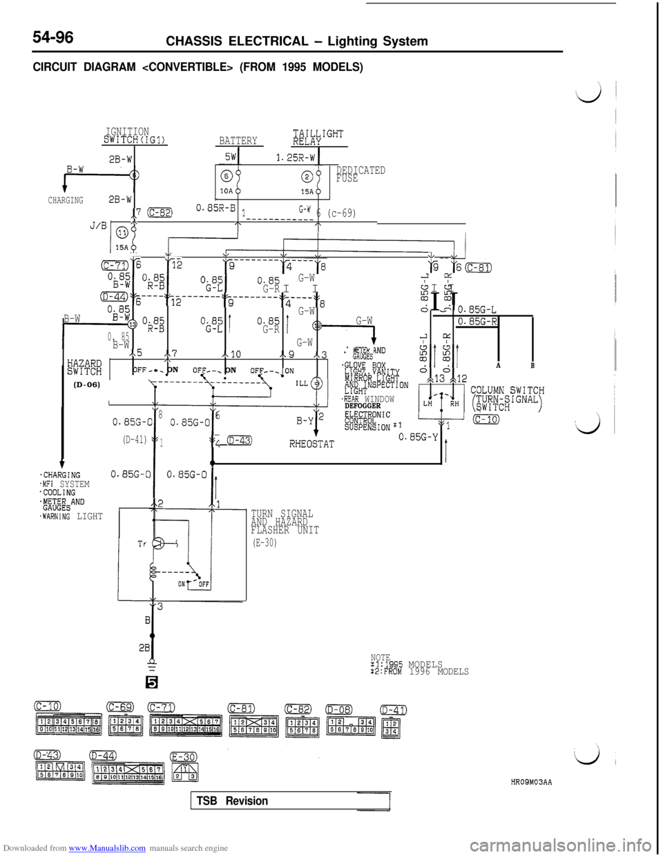
Downloaded from www.Manualslib.com manuals search engine 54-96CHASSIS ELECTRICAL - Lighting System
CIRCUIT DIAGRAM
IGNITIONSWITCH(IG?)BATTERY;&IGHT
2B-W1.25R-W
0DEDICATED
FUSE
15ACHARGING2B-wL
,,7 :c-82)0.85R-B lG-W 6 (c-69)/\J’BI mo
-___----____/\I\
B-W
f-
D-44)% ---- :T2 ------ -$~e---m--.~s---:~8%I I&
Og;G-WA&n
*3> “$2“i;“=!0.85
0. 85G-RI
B-WG-W
I/x5 .\7A10e9 x.3wmj,\. p!&'
OFF-c. ON
lOFF--. ON5 loF1;F-~oN m'R% thnrnnnb
G-W
1. .----iND
- - v.85G-L
0.85G-R
2 cc/ I.
E(D-06)IOX
'E%T'~~~J~~SPECTION
.REAR WINDOWDEFOGGERE#@;.NIC
SUSPENSIONzl
A
o,d3°gt12
B
\y---- --------
:c-?:,jE p2w
*\L &I--
a-7j% 166
“$ZI0.85G-W
G-RI I2 CL
& &I I
I
0.8%-(
(D-41)
38
I
0.85G-06
1:s; (D-43)RHEObAT0.85G-Y
qIt.CHARGING0.85G-C.MFI SYSTEM.COOLING+&$&ANDI.WARNING LIGHT
28
TURN SIGNAL
AND HAZARD
FLASHER UNIT
(E-30)
NOTEx1:1995 MODELSX2:FROM 1996 MODELS
HR09M03AA
TSB Revision
Page 607 of 738
Downloaded from www.Manualslib.com manuals search engine CHASSIS ELECTRICAL - Column Switch
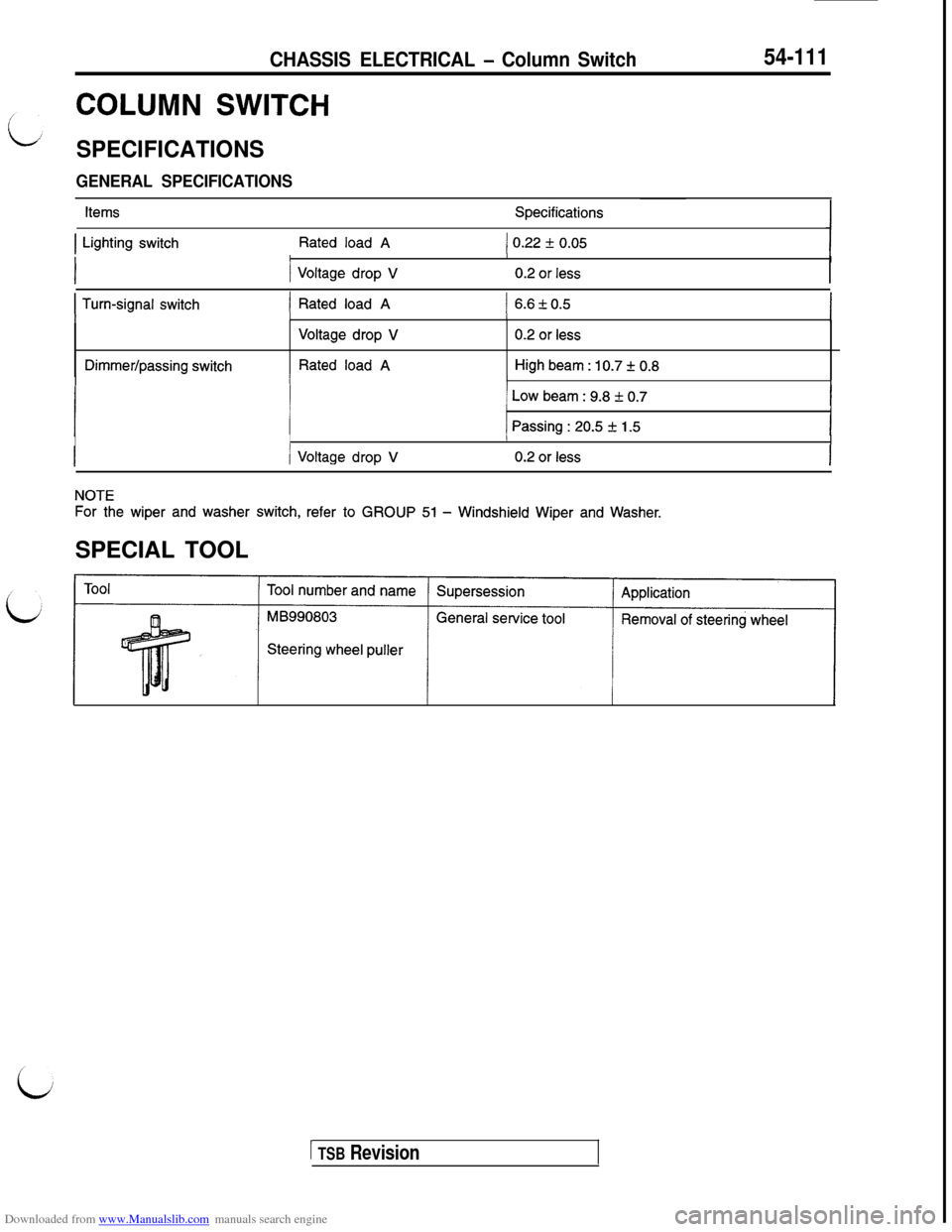
COLUMN SWITCH
SPECIFICATIONS
GENERAL SPECIFICATIONS
54-111
ItemsSpecifications
1 Lighting switchRated load A1 0.22 f 0.05IIII
1 Voltage drop V0.2 or less
I Turn-signal switch) Rated load A1 6.6kO.5III/I
Dimmer/passing switch
Voltage drop V
Rated load A
0.2 or less
High beam : 10.7 + 0.8IIII
1 Low beam : 9.8 f 0.7IIII
j Passing : 20.5 + 1.5IIII
/ Voltage drop V0.2 or less
NOTE
For the wiper and washer switch, refer to GROUP 51 - Windshield Wiper and Washer.SPECIAL TOOL
Steering wheel puller
1 TSB Revision
Page 608 of 738
Downloaded from www.Manualslib.com manuals search engine 54-112CHASSIS ELECTRICAL - Column SwitchCOLUMN SWITCH
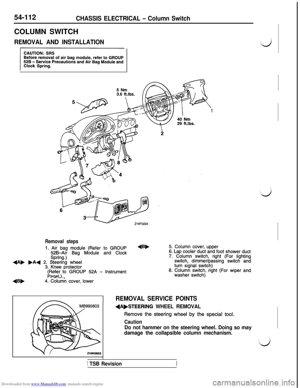
REMOVAL AND INSTALLATION
1
Removal steps
1. Air bag module (Refer to GROUP525Air Bag Module and ClockSpring.)+A, .A+ 2. Steering wheel3. Knee protector
4Bb
$F$i;)to GROUP 52A - Instrument
4. Column cover, lower
4B,5. Column cover, upper6. Lap cooler duct and foot shower duct7. Column switch, right (For lightingswitch, dimmer/passing switch andturn signal switch)8. Column switch, right (For wiper andwasher switch)
REMOVAL SERVICE POINTS
(A,STEERING WHEEL REMOVAL
Remove the steering wheel by the special tool.
Caution
Do not hammer on the steering wheel. Doing so may
damage the collapsible column mechanism.
1 TSB Revision
Page 610 of 738
Downloaded from www.Manualslib.com manuals search engine 54-114CHASSIS ELECTRICAL - Column Switch
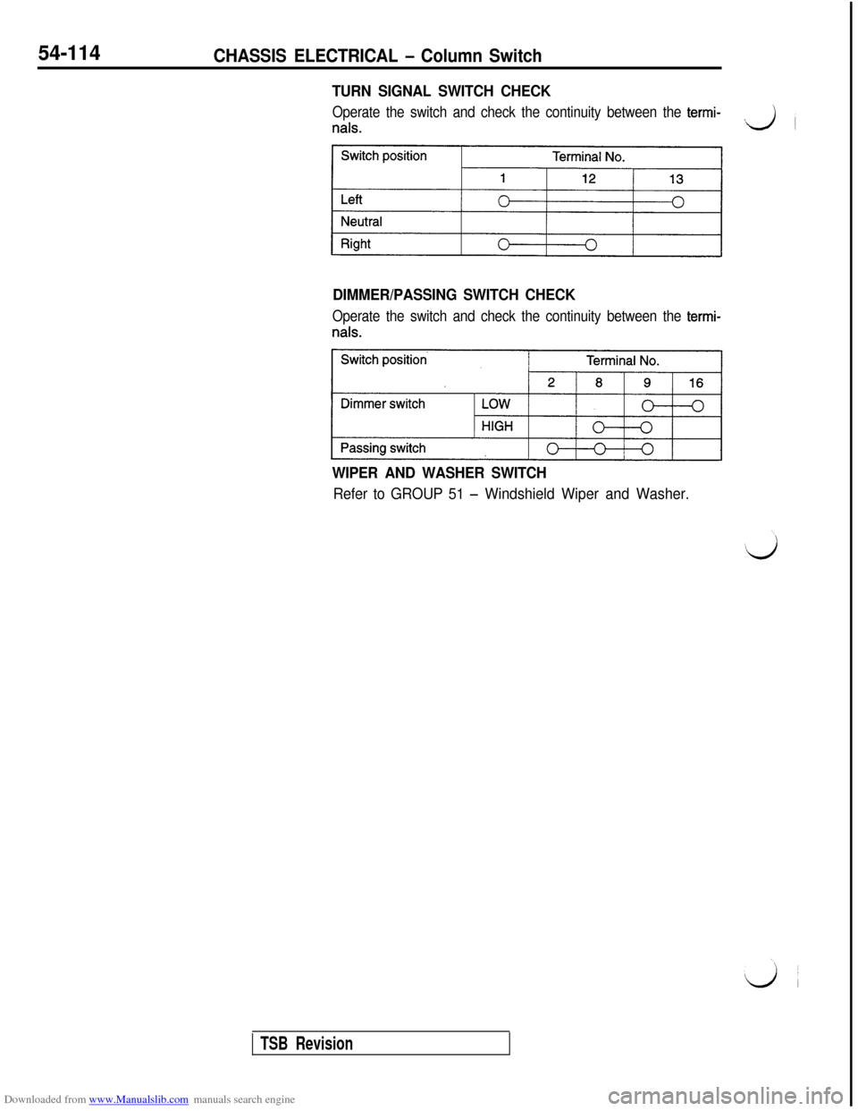
TURN SIGNAL SWITCH CHECK
Operate the switch and check the continuity between the termi-
nals.J
~
DIMMER/PASSING SWITCH CHECK
Operate the switch and check the continuity between the termi-
WIPER AND WASHER SWITCH
Refer to GROUP 51 - Windshield Wiper and Washer.
TSB Revision
Page 660 of 738
Downloaded from www.Manualslib.com manuals search engine 54-164CHASSIS ELECTRICAL - Radio and Tape Player
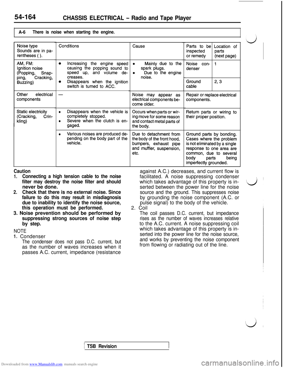
A-6There is noise when starting the engine.
Noise type
Sounds are in pa-
rentheses ( ).
AM, FM:
Ignition noise
(Popping, Snap-
ping,Cracking,
Buzzing)
Otherelectrical
components
Static electricity
(Cracking, Crin-
kling)
Conditions
0Increasing the engine speedcausing the popping sound tospeed up, and volume de-creases.0Disappears when the ignitionswitch is turned to ACC.
-
lDisappears when the vehicle is
completely stopped.Occurs when parts or wir-
Severe when the clutch is en-ing move for some reasonlgaged.and contact metal parts of
the body.
lVarious noises are produced de-pending on the body part of thevehicle.
Due to detachment from
the body of the front hood,
bumpers, exhaust pipe
and muffler, suspension,
etc.
Causel
Mainly due to the
spark plugs.l Due to the enginenoise.
Noise may appear as
electrical components be-
come older.
Parts to be Location of
inspectedparts
or remedy(next page)
Noise con- 1
denser
Ground
cable2, 3
Repair or replace electricalcomponents.
Return parts or wiring to
their proper position.
Caution
1.Connecting a high tension cable to the noise
filter may destroy the noise filter and shouldnever be done.
2.Check that there is no external noise. Since
failure to do this may result in misdiagnosis
due to inability to identify the noise source,
this operation must be performed.3. Noise prevention should be performed by
suppressing strong sources of noise step
by step.
NOTE
1. Condenser
The condenser does not pass D.C. current, butas the number of waves increases when it
passes A.C. current, impedance (resistanceagainst A.C.) decreases, and current flow is
facilitated. A noise suppressing condenser
which takes advantage of this property is in-
serted between the power line for the noise
source and the ground. This suppresses noiseby grounding the noise component (A.C. or
pulse signal) to the body of the vehicle.
2. Coil
The coil passes D.C. current, but impedance
rises as the number of waves increases relativeto the A.C. current. A noise suppressing coil
which takes advantage of this property is in-
serted into the power line for the noise source,
and works by preventing the noise componentfrom flowing or radiating out of the line.
1 TSB Revision
Ground parts by bonding.
Cases where the problem
is not eliminated by a single
response to one area are
common, due to several
bodypartsbeing
imperfectly grounded.
Page 663 of 738
Downloaded from www.Manualslib.com manuals search engine CHASSIS ELECTRICAL - Radio and Tape Player54-167
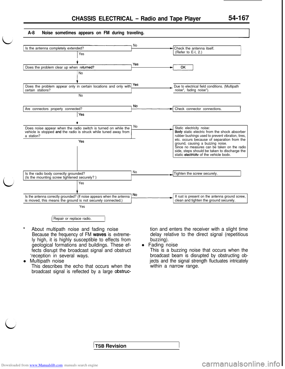
A-8Noise sometimes appears on FM during traveling.
NoIs the antenna completely extended?
Yes
t Check the antenna itself.
(Refer to E-l, 2.)
+Does the problem clear up whenre
1 No
Yes
iDoes the problem appear only in certain locations and only with yes
certain stations?
No
~ Due to electrical field conditions. (Multipath
noise*, fading noise*).
Are connectors property connected?
Yes
Check connector connections.1
tDoes noise appear when the radio switch is turned on while the
vehicle is stopped
and the radio is struck while tuned away froma station?
Yes
No*Static electricity noise:Sody static electric from the shock absorberrubber bushings used to prevent vibration, tires,etc. occurs because of separation from the
ground, causing a buzzing noise.
Since no measures can be taken on the radioside, steps should be taken to discharge the
static
electricitv of the vehicle bodv.
Is the radio body correctly grounded?
No(Is the mounting screw tightened securely?
)
Yes
-) Tighten the screw securely.I
Is the antenna correctly grounded? (If noise appears when the antennais moved, this means the ground is not securely connected.)
Yes
If rust is present on the antenna ground screw,clean and tighten the ground securely.
*
1 Repair or replace radio.1
About multipath noise and fading noise
Because the frequency of FM waves is extreme-
ly high, it is highly susceptible to effects from
geological formations and buildings. These ef-
fects disrupt the broadcast signal and obstruct
‘reception in several ways.l Multipath noise
This describes the echo that occurs when the
broadcast signal is reflected by a large obstruc-
tion and enters the receiver with a slight time
delay relative to the direct signal (repetitious
buzzing).l Fading noise
This is a buzzing noise that occurs when the
broadcast beam is disrupted by obstructing ob-
jects and the signal strength fluctuates intricately
within a narrow range.
1 TSB Revision
Page 698 of 738
Downloaded from www.Manualslib.com manuals search engine 54-202CHASSIS ELECTRICAL - Rear Window Defogger
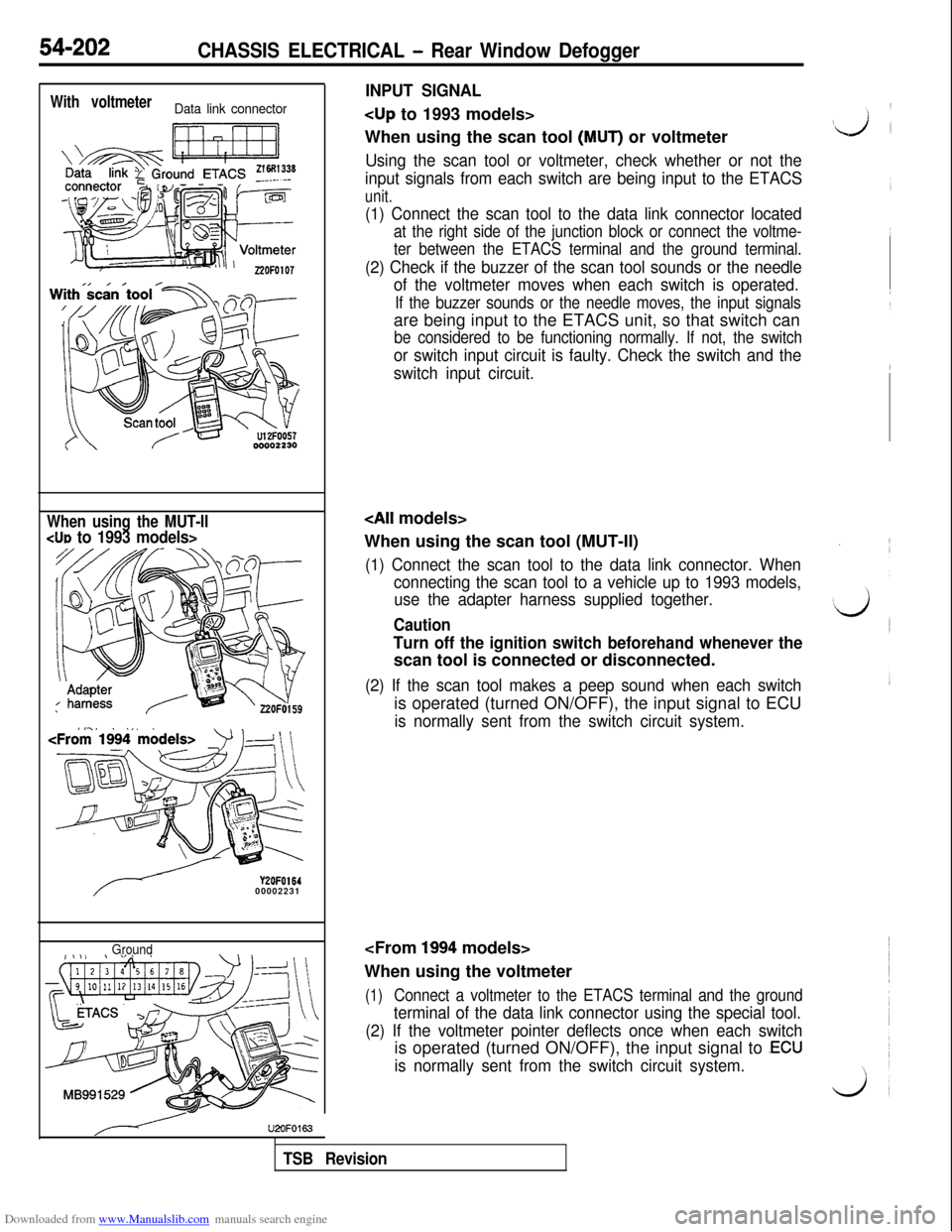
With voltmeterData link connector
When using the MUT-IICUD to 1993 models>
Y2OFO16400002231
Ground
INPUT SIGNAL
When using the scan tool
(MUT) or voltmeter
Using the scan tool or voltmeter, check whether or not the
input signals from each switch are being input to the ETACS
unit.
(1) Connect the scan tool to the data link connector located
at the right side of the junction block or connect the voltme-
ter between the ETACS terminal and the ground terminal.
(2) Check if the buzzer of the scan tool sounds or the needle
of the voltmeter moves when each switch is operated.
If the buzzer sounds or the needle moves, the input signalsare being input to the ETACS unit, so that switch can
be considered to be functioning normally. If not, the switch
or switch input circuit is faulty. Check the switch and the
switch input circuit.
When using the scan tool (MUT-II)
(1) Connect the scan tool to the data link connector. When
connecting the scan tool to a vehicle up to 1993 models,
use the adapter harness supplied together.
Caution
Turn off the ignition switch beforehand whenever thescan tool is connected or disconnected.
(2) If the scan tool makes a peep sound when each switchis operated (turned ON/OFF), the input signal to ECU
is normally sent from the switch circuit system.
When using the voltmeter
(1)Connect a voltmeter to the ETACS terminal and the ground
terminal of the data link connector using the special tool.
(2) If the voltmeter pointer deflects once when each switchis operated (turned ON/OFF), the input signal to
.ECU
is normally sent from the switch circuit system.
U2OFO163
TSB Revision