stop start MITSUBISHI 3000GT 1992 2.G Workshop Manual
[x] Cancel search | Manufacturer: MITSUBISHI, Model Year: 1992, Model line: 3000GT, Model: MITSUBISHI 3000GT 1992 2.GPages: 738, PDF Size: 35.06 MB
Page 54 of 738
Downloaded from www.Manualslib.com manuals search engine 52CONFIGURATION DIAGRAMS - Dash Panel
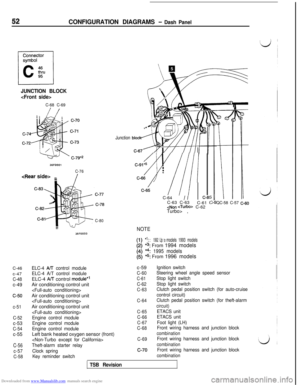
JUNCTION BLOCK
C-68 C-69C-46
c-47
C-48c-49
c-50
c-51
C-52c-53
C-54c-55
C-56
c-57
C-58
36FOOOl
C-76
/
C-80
36FOOO3
Junction
/C-91*5 i
Av///I :-C-64
1 /:-8!C-63 C-63
C-61
(
Turbo> ,
NOTE
[-I!1:: :1992 Up tomodels 1993 models
*s: From 1994 models
*4:1995models
(5)*5: From 1996 models
QC-58 C-57 C-60
ELC-4 AA control module
ELC-4 A/T control moduleELC-4
AiT control module*’Air conditioning control unit
Engine control module
Engine control module
Engine control moduleLeft bank heated oxygen sensor (front)
Theft-alarm starter relay
Clock spring
Key reminder switchc-59
C-60
C-61
C-62
C-63
C-64
C-65
C-66
C-67
C-68
C-69c-70
Ignition switch
Steering wheel angle speed sensor
Stop light switch
Stop light switch
Clutch pedal position switch (for auto-cruise
control circuit)
Clutch pedal position switch (for theft-alarm
circuit)
ETACS unit
ETACS unit
Foot light (LH)
Front wiring harness and junction block
combination
Front wiring harness and junction block
combination
Front wiring harness and junction block
combinationITSB Revision
Page 63 of 738
Downloaded from www.Manualslib.com manuals search engine 61
i
CIRCUIT
DlAG.RAMS
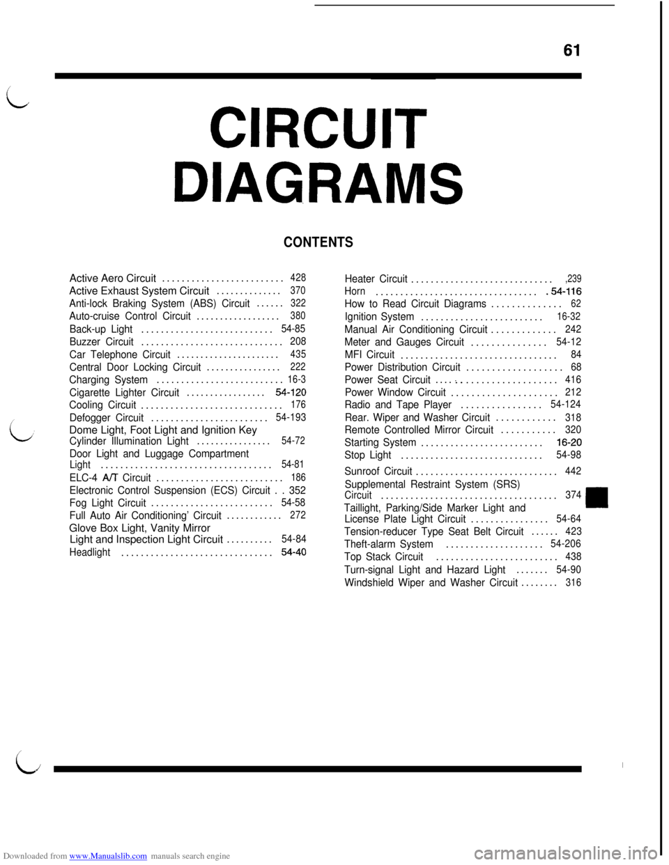
CONTENTSActive Aero Circuit.........................
428Active Exhaust System Circuit..............
370
Anti-lock Braking System (ABS) Circuit......322
Auto-cruise Control Circuit..................380
Back-up Light...........................54-85
Buzzer Circuit.............................208
Car Telephone Circuit......................435
Central Door Locking Circuit................222
Charging System..........................16-3
Cigarette Lighter Circuit.................54-120
Cooling Circuit.............................176
Defogger Circuit........................54-193Dome Light, Foot Light and Ignition Key
Cylinder Illumination Light................54-72
Door Light and Luggage Compartment
Light...................................54-81
ELC-4 A/T Circuit..........................186
Electronic Control Suspension (ECS) Circuit . . 352
Fog Light Circuit.........................
54-58
Full Auto Air Conditioning’ Circuit............272Glove Box Light, Vanity Mirror
Light and Inspection Light Circuit..........
54-84
Headlight...............................
54-40
Heater Circuit.............................,239
Horn..................................54-116
How to Read Circuit Diagrams..............
62
Ignition System.........................16-32
Manual Air Conditioning Circuit.............242
Meter and Gauges Circuit...............54-12
MFI Circuit................................84
Power Distribution Circuit...................68
Power Seat Circuit....:...................416
Power Window Circuit.....................212
Radio and Tape Player................54-124
Rear. Wiper and Washer Circuit............318
Remote Controlled Mirror Circuit...........320
Starting System.........................16-20
Stop Light.............................54-98
Sunroof Circuit.............................442
Supplemental Restraint System (SRS)
Circuit....................................374
Taillight, Parking/Side Marker Light and
License Plate Light Circuit................54-64
Tension-reducer Type Seat Belt Circuit......423
Theft-alarm System....................54-206
Top Stack Circuit.........................438
Turn-signal Light and Hazard Light.......54-90
Windshield Wiper and Washer Circuit........316
I
LiI
Page 76 of 738
Downloaded from www.Manualslib.com manuals search engine CIRCUIT DIAGRAMS - Power Distribution Circuit
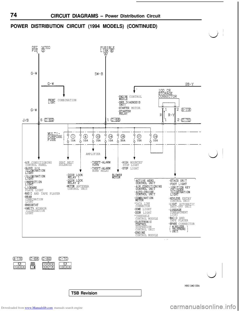
POWER DISTRIBUTION CIRCUIT (1994 MODELS) (CONTINUED)
,ij ’
G-W
G-W
J/B
5W-B
G-W
[Pgfi; COMBINATION
.AIR CONDITIONINGSEAT BELT.HIGH MOUNTEDCONTROL PANELSOLENOIDT'#;;T-ALARMSTOP LIGHT.GLOVE BOX.THEFT-ALARM.STOP LIGHT.ILJ&INATION
HORN RELAY
MULTI-
RE"""
AMPLIFIER
2B-Y*
+-IOD ORSTORAGE43WFE CONTROLCONNECTOR
S;SRTDIAGNOSIS
.STARTER MOTOR
~3%""
LIGHI~~~l&INATION
dM&CT'ON
.LICENSEPLATE LIGHT.RADIO AND TAPE PLAYER.REARCOMBINATION
LIGHT
.RHEOSTAT.VANITY MIRRORILLUMINATIONLIGHT
*fi;;~yL~CK
'i&fEyLgCK
.MOTOR ANTENNACONTROL UNIT
$#~~NATION
*DATA LINKCONNECTOR.DOME LIGHT.DOOR LIGHT*TRANSAXLECONTROL MODULE
.KEYLESS ENTRYCONTROL UNIT,LIGHT AUTOMATICSHUT-OFF UNIT.LUGGAGECOMPARTMENTLIGHT.RADIO ANDTAPE PLAYER.SPARE CONNECTOR
i ~~~@i~wE I
E~;LE;[~NIC
SUSPENSION
CONTROL UNIT
.ENGINE\ UN11/
CONTROL MODULE
HROlMOlBA
TSB Revision
Page 451 of 738
Downloaded from www.Manualslib.com manuals search engine ENGINE ELECTRICAL - Charging System16-5
OPERATION
When engine is stoppedWhen the ignition switch is switched to the “ON”
position, electricity flows from the
‘I” terminal of
the generator to the field coil, and at the same time
the charging warning light illuminates.
When engine is being started/has started
When the engine is started, charging voltage is ap-
plied to the ‘I” terminal of the generator, with the
result that the charging warning light is extinguished.
In addition, because battery voltage is applied to
the “S” terminal of the generator, this battery voltage
is monitored at the
IC voltage regulator, thus switch-ing ON and OFF the current to the field coil and
thereby controlling the output voltage of the genera-
tor.
Power is supplied to each load from the “B” terminal
of the generator.
NOTE
The generator relay functions as a back-up for the
flow of electricity to the field coil if there is a discon-
nection or damaged wiring of the charging warning
light.
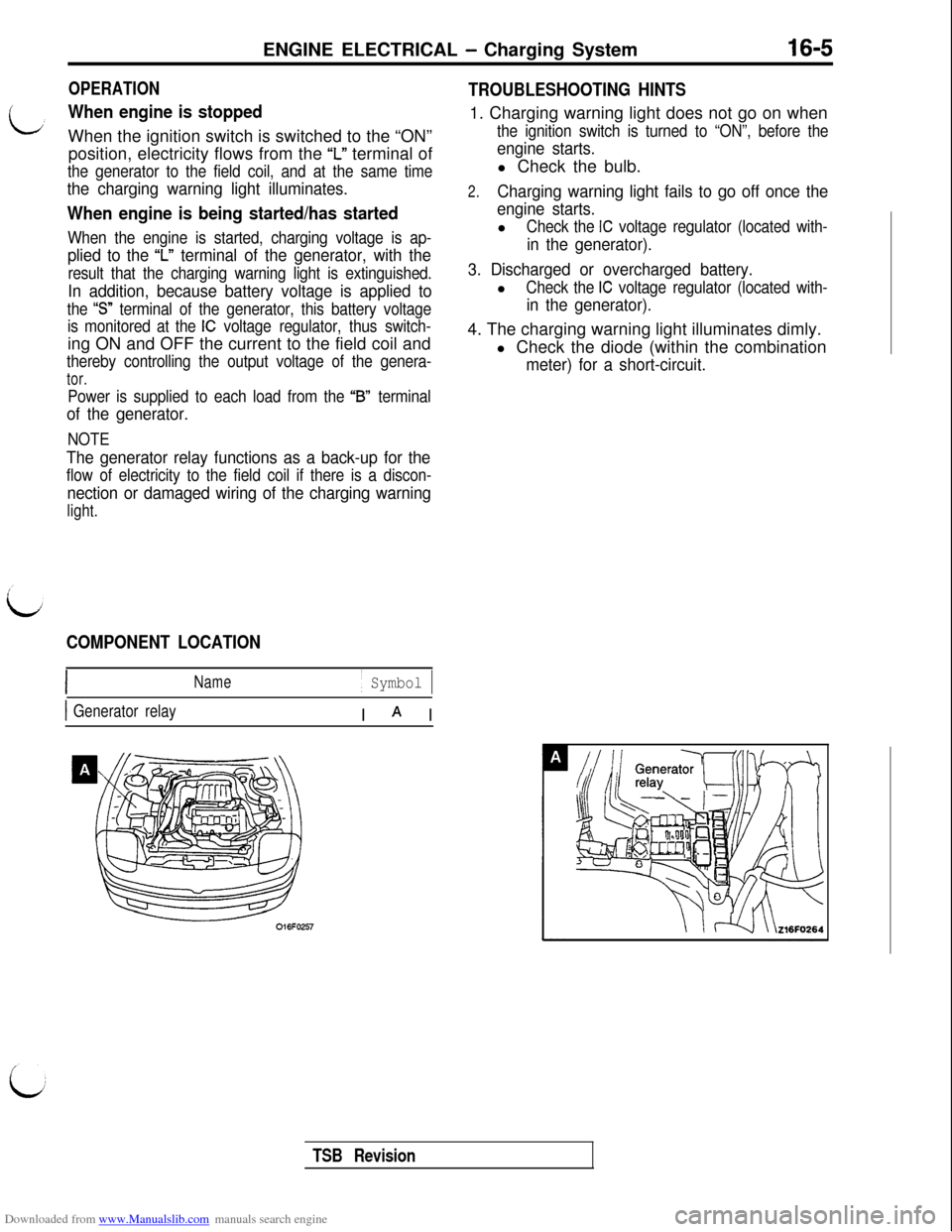
COMPONENT LOCATION
Name/ Symbol 1
1 Generator relayI A I
TROUBLESHOOTING HINTS1. Charging warning light does not go on when
the ignition switch is turned to “ON”, before the
engine starts.l Check the bulb.
2.Charging warning light fails to go off once the
engine starts.l
Check the IC voltage regulator (located with-
in the generator).
3. Discharged or overcharged battery.l
Check the IC voltage regulator (located with-
in the generator).4. The charging warning light illuminates dimly.
l Check the diode (within the combination
meter) for a short-circuit.
TSB Revision
Page 469 of 738
Downloaded from www.Manualslib.com manuals search engine ENGINE ELECTRICAL - Starting System16-23
OPERATION
L
0For models equipped with the M/T, the clutch
pedal position switch contact is switched OFF
when the clutch pedal is depressed; when the
ignition switch is then switched to the “ST’ posi-tion, electricity flows to the starter relay and
the starter motor, the contact (magnetic switch)of the starter is switched ON and the starter
motor is activated.
NOTEIf the ignition switch is switched to the “ST
position without the clutch pedal being de-
pressed, electricity flows to the starter relay
(coil), the clutch pedal position switch (contacts)
and to ground, with the result that the contacts
of the starter relay are switched OFF, and, be-
cause the power to the starter motor is thereby
interrupted, the starter motor is not activated.lFor models equipped with the
AIT, when the
ignition switch is switched to the “ST’ position
while the selector lever is at the “P” or “N” posi-
tion, the contact (magnetic switch) of the starter
is switched ON and the starter motor is activated.
TROUBLESHOOTING HINTSThe starter motor does not operate at all.
l Check the starter (coil).
lCheck for poor contact at the battery terminals
and starter.l Check Park/Neutral position switch.
l Check clutch pedal position switch.
l Check starter relay.
l Check theft-alarm starter relay.
l Check key reminder switch.
i
/’
L&J
Fieldcoil wire
Iii?Stopper
IPinion gap
PinionZ6EL003
STARTER MOTORREMOVAL AND INSTALLATION
Refer to GROUP 22
- Manual Transaxle, or GROUP 23 -
Automatic Transaxle.INSPECTION
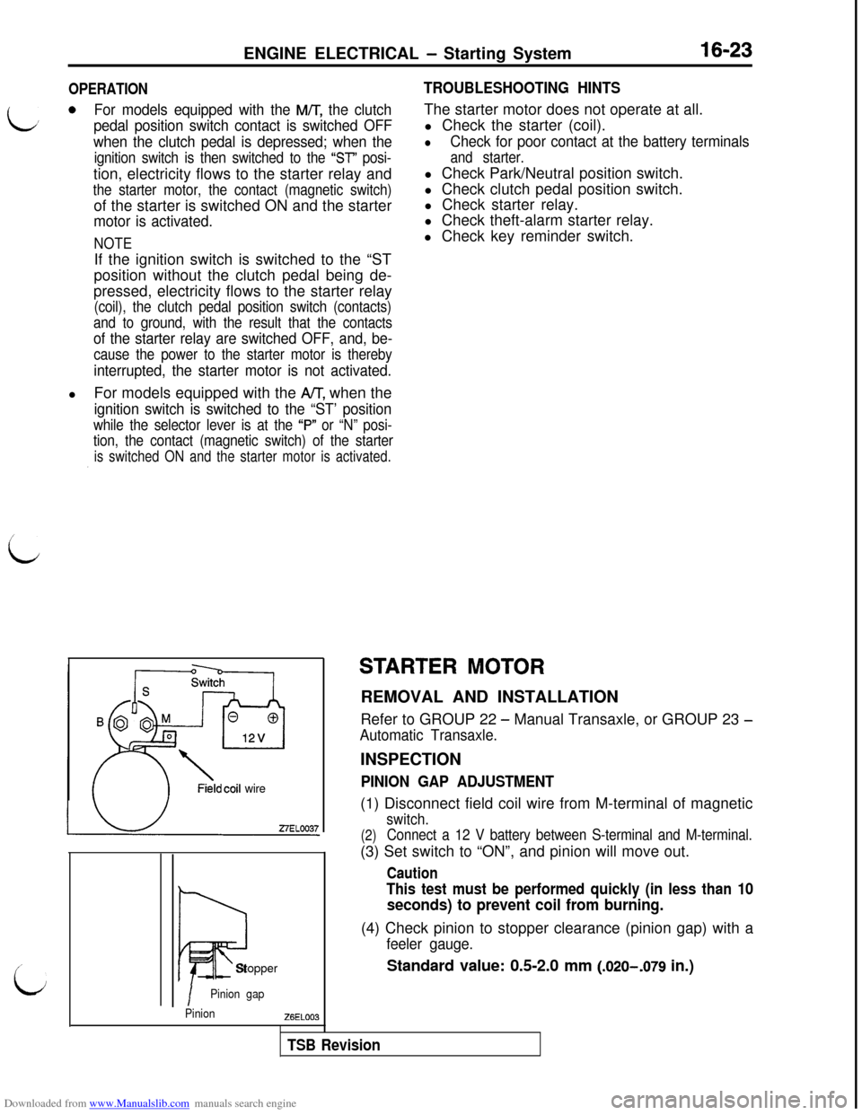
PINION GAP ADJUSTMENT(1) Disconnect field coil wire from M-terminal of magnetic
switch.
(2)Connect a 12 V battery between S-terminal and M-terminal.(3) Set switch to “ON”, and pinion will move out.
Caution
This test must be performed quickly (in less than 10
seconds) to prevent coil from burning.(4) Check pinion to stopper clearance (pinion gap) with a
feeler gauge.
Standard value: 0.5-2.0 mm (.020-,079 in.)
TSB Revision
Page 470 of 738
Downloaded from www.Manualslib.com manuals search engine 16-24ENGINE ELECTRICAL - Starting System
ZlEL11327ELOOlQ
0
5
Startermotor
Carbon-pile rheostat
-I-Battery
i12v I
Voltmeter7-II27ELOO22(5) If pinion gap is out of specification, adjust by adding or
removing gaskets between magnetic switch and front
bracket.
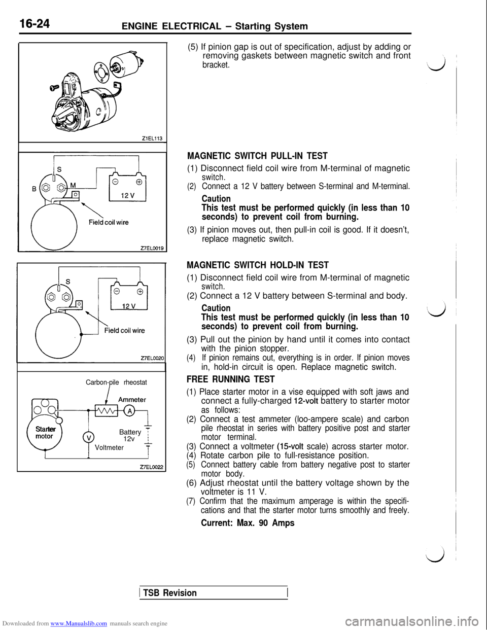
MAGNETIC SWITCH PULL-IN TEST(1) Disconnect field coil wire from M-terminal of magnetic
switch.
(2)
Connect a 12 V battery between S-terminal and M-terminal.
Caution
This test must be performed quickly (in less than 10
seconds) to prevent coil from burning.
(3) If pinion moves out, then pull-in coil is good. If it doesn’t,
replace magnetic switch.
MAGNETIC SWITCH HOLD-IN TEST(1) Disconnect field coil wire from M-terminal of magnetic
switch.(2) Connect a 12 V battery between S-terminal and body.
Caution
This test must be performed quickly (in less than 10
seconds) to prevent coil from burning.(3) Pull out the pinion by hand until it comes into contact
with the pinion stopper.
(4)If pinion remains out, everything is in order. If pinion moves
in, hold-in circuit is open. Replace magnetic switch.
FREE RUNNING TEST
(1) Place starter motor in a vise equipped with soft jaws andconnect a fully-charged
12-volt battery to starter motor
as follows:
(2) Connect a test ammeter (loo-ampere scale) and carbon
pile rheostat in series with battery positive post and starter
motor terminal.
(3) Connect a voltmeter (15volt scale) across starter motor.
(4) Rotate carbon pile to full-resistance position.
(5)Connect battery cable from battery negative post to starter
motor body.(6) Adjust rheostat until the battery voltage shown by the
voltmeter is 11 V.
(7) Confirm that the maximum amperage is within the specifi-
cations and that the starter motor turns smoothly and freely.
Current: Max. 90 Amps
1 TSB Revision
Page 472 of 738
Downloaded from www.Manualslib.com manuals search engine 16-26ENGINE ELECTRICAL - Starting System
DISASSEMBLY AND REASSEMBLY
I
Lj~
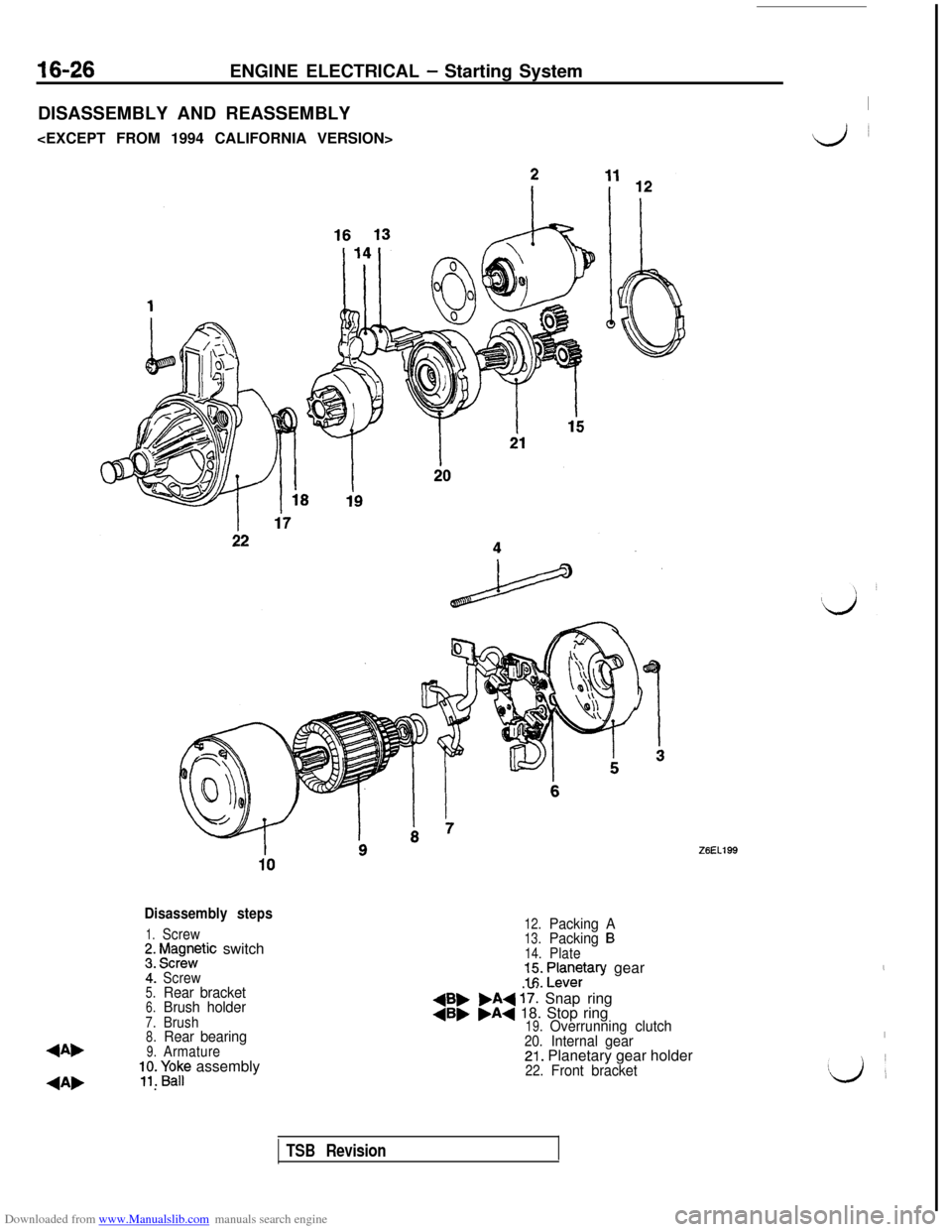
Disassembly steps
1.Screw;. f$gnntic switch
4:Screw5.Rear bracket6.Brush holder7.Brush8.Rear bearing
4Ab9.Armature;;. paF assembly
4A, .
12.Packing A13.Packing B14.Plate=I:. ;an$ary gear
+B, .A+ 17: Snap ring4B, .A+ 18. Stop ring19.Overrunning clutch20.Internal gear21. Planetary gear holder22.Front bracket
,
I!Lj
’
TSB Revision
Page 473 of 738
Downloaded from www.Manualslib.com manuals search engine ENGINE ELECTRICAL - Starting System16-27
27EN0628
1'0
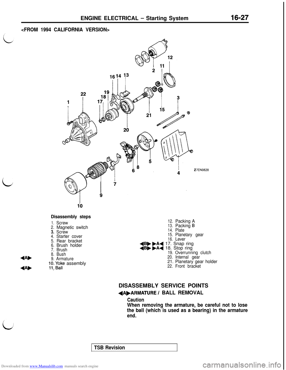
Disassembly steps
1.Screw2.Magnetic switch3.Screw4.Starter cover5.Rear bracket6.Brush holder7.Brush8.Bush4A,9.Armature;y. Fap assembly
4A, .
12.Packing A13.Packing B
14.Plate
15.Planetary gear16.Lever4B, .A4 17. Snap ring4B, .A4 18. Stop ring19.Overrunning clutch20.Internal gear21. Planetary gear holder22.Front bracketDISASSEMBLY SERVICE POINTS
+A,ARMATURE / BALL REMOVAL
Caution
When removing the armature, be careful not to lose
the ball (which is used as a bearing) in the armature
end.
TSB Revision
Page 474 of 738
Downloaded from www.Manualslib.com manuals search engine 16-28ENGINE ELECTRICAL - Starting System
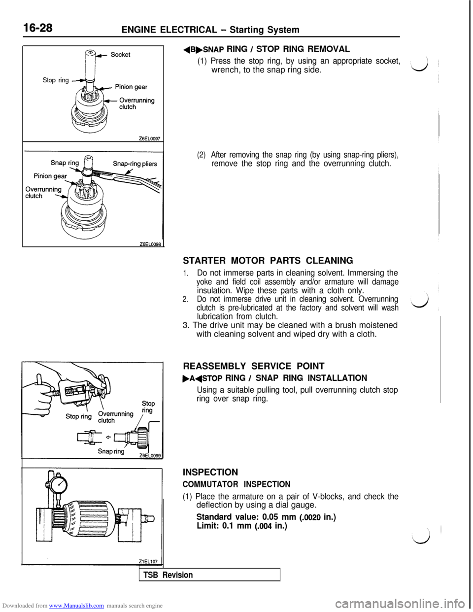
Stop ringZ6EL0097
Z6ELOO96+B,SNAP
RING / STOP RING REMOVAL
(1) Press the stop ring, by using an appropriate socket,wrench, to the snap ring side.
(2)After removing the snap ring (by using snap-ring pliers),
remove the stop ring and the overrunning clutch.STARTER MOTOR PARTS CLEANING
1.Do not immerse parts in cleaning solvent. Immersing the
yoke and field coil assembly and/or armature will damage
insulation. Wipe these parts with a cloth only.
2.Do not immerse drive unit in cleaning solvent. Overrunning
clutch is pre-lubricated at the factory and solvent will wash
lubrication from clutch.3. The drive unit may be cleaned with a brush moistened
with cleaning solvent and wiped dry with a cloth.
REASSEMBLY SERVICE POINT
,A+TOP RING / SNAP RING INSTALLATION
Using a suitable pulling tool, pull overrunning clutch stop
ring over snap ring.INSPECTION
COMMUTATOR INSPECTION
(1) Place the armature on a pair of V-blocks, and check thedeflection by using a dial gauge.
Standard value: 0.05 mm (JO20 in.)
Limit: 0.1 mm
(.004 in.)
TSB Revision
Page 612 of 738
Downloaded from www.Manualslib.com manuals search engine 54-116CHASSIS ELECTRICAL - Horn
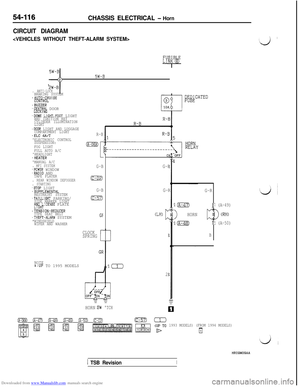
CIRCUIT DIAGRAM
c
5W-B;;-j
. ANTI-LOCKBRAKING SYSTEM*&$@lJUISE
.BUZZER*E;~CT~R~ DOOR
.DOME LIGHTsFOOT LIGHTAND IGNITION KEY
CYLINDER ILLUMINATION
LIGHT
.DOOR LIGHT AND LUGGAGECOMPARTMENT LIGHT.ELC 4A/T'ELECTRONIC CONTROL
SUSPENSION:
FOG LIGHT
FULL AUTO A/C
'HEADLIGHT
.HEATER
'MANUAL A/C
. MFI SYSTEM.POWER WINDOW.RADIO ANDTAPE PLAYER. REAR WINDOW DEFOGGER. STARTING.STOP LIGHT.SUPPLEMENTAL
RESTRAINT SYSTEM
.TAILLIGHT PARKING/SIDE MARKER LIGHTfJy;H;ICENSE PLATE
.TENSION-REDUCER
TYPE SEAT BELT
.THEFT-ALARM SYSTEM*WINDSHIELD
WIPER AND WASHER
NOTE::UP TO 1995 MODELS
R-B
(A-06X)
I
G-B
(c-02)
G-B
(c-57)
GF
CLOCK
SPRING
[
GE
;;&CATED
G-R
!(
2E=
HORNG-R
(LH)c
E
=
'TCH
G-R
l(A-47),l (A-49)
>HORN
l(A-48)"1 (A-50)
B
0 (A-47) oFa (A-49) ofiml (c-02)(c-57)=
1993 MODELS) (FROM 1994 MODELS)
El
‘J ’
HROSMOSAA
1 TSB RevisionI