ESP inoperative MITSUBISHI 3000GT 1993 2.G Workshop Manual
[x] Cancel search | Manufacturer: MITSUBISHI, Model Year: 1993, Model line: 3000GT, Model: MITSUBISHI 3000GT 1993 2.GPages: 738, PDF Size: 35.06 MB
Page 317 of 738

Downloaded from www.Manualslib.com manuals search engine CIRCUIT DIAGRAMS - Windshield Wiper and Washer Circuit315
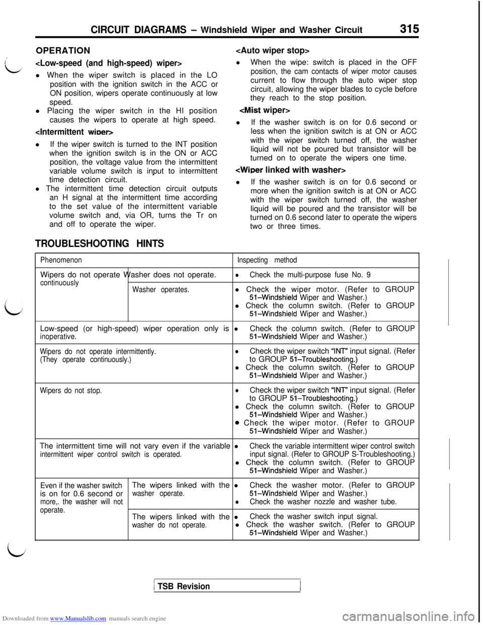
OPERATION
L
l When the wiper switch is placed in the LO
position, the cam contacts of wiper motor causesposition with the ignition switch in the ACC orcurrent to flow through the auto wiper stop
ON position, wipers operate continuously at lowcircuit, allowing the wiper blades to cycle before
speed.they reach to the stop position.
l Placing the wiper switch in the HI position
causes the wipers to operate at high speed.
lIf the washer switch is on for 0.6 second or
less when the ignition switch is at ON or ACC
lIf the wiper switch is turned to the INT positionwith the wiper switch turned off, the washer
when the ignition switch is in the ON or ACCliquid will not be poured but transistor will be
position, the voltage value from the intermittentturned on to operate the wipers one time.
variable volume switch is input to intermittent
’time detection circuit.
l The intermittent time detection circuit outputs
an H signal at the intermittent time according
to the set value of the intermittent variable
volume switch and, via OR, turns the Tr on
and off to operate the wiper.lIf the washer switch is on for 0.6 second or
more when the ignition switch is at ON or ACC
with the wiper switch turned off, the washer
liquid will be poured and the transistor will be
turned on 0.6 second later to operate the wipers
two or three times.
TROUBLESHOOTING HINTS
L
PhenomenonWipers do not operate Washer does not operate.
continuously
Washer operates.Inspecting method
lCheck the multi-purpose fuse No. 9l Check the wiper motor. (Refer to GROUPS-Windshield
Wiper and Washer.)l Check the column switch. (Refer to GROUPS-Windshield
Wiper and Washer.)Low-speed (or high-speed) wiper operation only is l
inoperative.Check the column switch. (Refer to GROUP51-Windshield Wiper and Washer.)
Wipers do not operate intermittently.
(They operate continuously.)lCheck the wiper switch “INT” input signal. (Refer
to GROUP
51-Troubleshooting.)l Check the column switch. (Refer to GROUPS-Windshield
Wiper and Washer.)
Wipers do not stop.lCheck the wiper switch “INT” input signal. (Refer
to GROUP
51-Troubleshooting.)l Check the column switch. (Refer to GROUP
51-Windshield Wiper and Washer.)
o Check the wiper motor. (Refer to GROUP
51-Windshield Wiper and Washer.)The intermittent time will not vary even if the variable l
intermittent wiper control switch is operated.
Check the variable intermittent wiper control switch
input signal. (Refer to GROUP S-Troubleshooting.)l Check the column switch. (Refer to GROUP
51-Windshield Wiper and Washer.)
Even if the washer switchThe wipers linked with the lCheck the washer motor. (Refer to GROUP
is on for 0.6 second or
washer operate.51-Windshield Wiper and Washer.)
more,. the washer will notlCheck the washer nozzle and washer tube.
operate.The wipers linked with the lCheck the washer switch input signal.
washer do not operate.l Check the washer switch. (Refer to GROUP51-Windshield Wiper and Washer.)
1 TSB Revision
Page 497 of 738

Downloaded from www.Manualslib.com manuals search engine 54-1
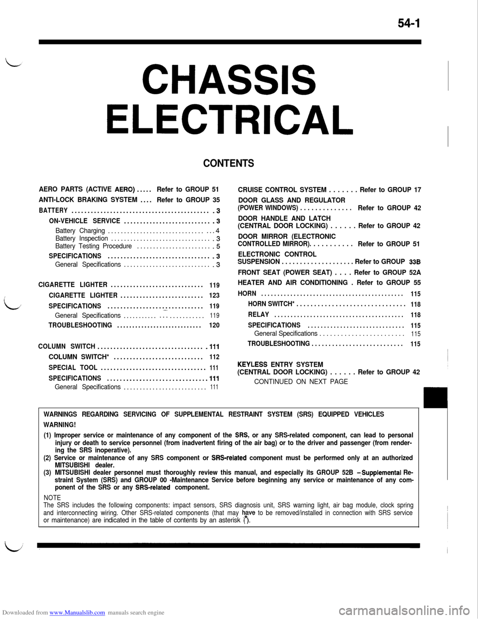
CHASSIS
ELECTRICAL
CONTENTS
AERO PARTS (ACTIVE AERO).....Refer to GROUP 51
ANTI-LOCK BRAKING SYSTEM....
Refer to GROUP 35
BATTERY...........................................-3
ON-VEHICLE SERVICE............................3
Battery Charging.................................4Battery Inspection................................3Battery Testing Procedure........................5
SPECIFICATIONS................................-3
General Specifications............................3
CIGARETTE LIGHTER.............................119
CIGARETTE LIGHTER..........................123
SPECIFICATIONS..............................
119
General Specifications............I...........119
TROUBLESHOOTING............................120
COLUMN SWITCH.................................
.lll
COLUMN SWITCH*............................112
SPECIAL TOOL.................................111
SPECIFICATIONS...............................111
General Specifications..........................111
CRUISE CONTROL SYSTEM . . . . . . . Refer to GROUP 17
DOOR GLASS AND REGULATOR
(POWER WINDOWS) . . . . . . . . . . . . . .Refer to GROUP 42
DOOR HANDLE AND LATCH
(CENTRAL DOOR LOCKING) . . . . . . Refer to GROUP 42
DOOR MIRROR (ELECTRONIC
CONTROLLED MIRROR). . . . . . . . . . .Refer to GROUP 51
ELECTRONIC CONTROL
SUSPENSION . . . . . . . . . . . . . . . . . . . . Refer to GROUP
338
FRONT SEAT (POWER SEAT) . . . . Refer to GROUP 52A
HEATER AND AIR CONDITIONING . Refer to GROUP 55
HORN. . . . . . . . . . . . . . . . . . . . . . . . . . . . . . . . . . . . . . . . . . . .
115
HORN SWITCH* . . . . . . . . . . . . . . . . . . . . . . . . . . . . . . .118
RELAY. . . . . . . . . . . . . . . . . . . . . . . . . . . . . . . . . . . . . . . .
118
SPECIFICATIONS. . . . . . . . . . . . . . . . . . . . . . . . . . . . . .
115
General Specifications . . . . . . . . . . . . . . . . . . . . . . . .115
TROUBLESHOOTING . . . . . . . . . . . . . . . . . . . . . . . . . . .115
KEYLESS ENTRY SYSTEM
(CENTRAL DOOR LOCKING) . . . . . . Refer to GROUP 42
CONTINUED ON NEXT PAGE
WARNINGS REGARDING SERVICING OF SUPPLEMENTAL RESTRAINT SYSTEM (SRS) EQUIPPED VEHICLES
WARNING!
(1) Improper service or maintenance of any component of the
SRS, or any SRS-related component, can lead to personal
injury or death to service personnel (from inadvertent firing of the air bag) or to the driver and passenger (from render-
ing the SRS inoperative).
(2) Service or maintenance of any SRS component or
SRS-related component must be performed only at an authorized
MITSUBISHI dealer.
(3)MITSUBISHI dealer personnel must thoroughly review this manual, and especially its GROUP 52B
TSupplemental Re-
straint System (SRS) and GROUP 00 -Maintenance Service before beginning any service or maintenance of any com-
ponent of the SRS or any
SRS-related component.
NOTE
The SRS includes the following components: impact sensors, SRS diagnosis unit, SRS warning light, air bag module, clock spring
and interconnecting wiring. Other SRS-related components (that may
h,a”” to be removed/installed in connection with SRS serviceor maintenance) are indicated in the table of contents by an asterisk ( ).