clock MITSUBISHI 3000GT 1994 2.G User Guide
[x] Cancel search | Manufacturer: MITSUBISHI, Model Year: 1994, Model line: 3000GT, Model: MITSUBISHI 3000GT 1994 2.GPages: 738, PDF Size: 35.06 MB
Page 600 of 738
Downloaded from www.Manualslib.com manuals search engine CHASSIS ELECTRICAL - Lighting System
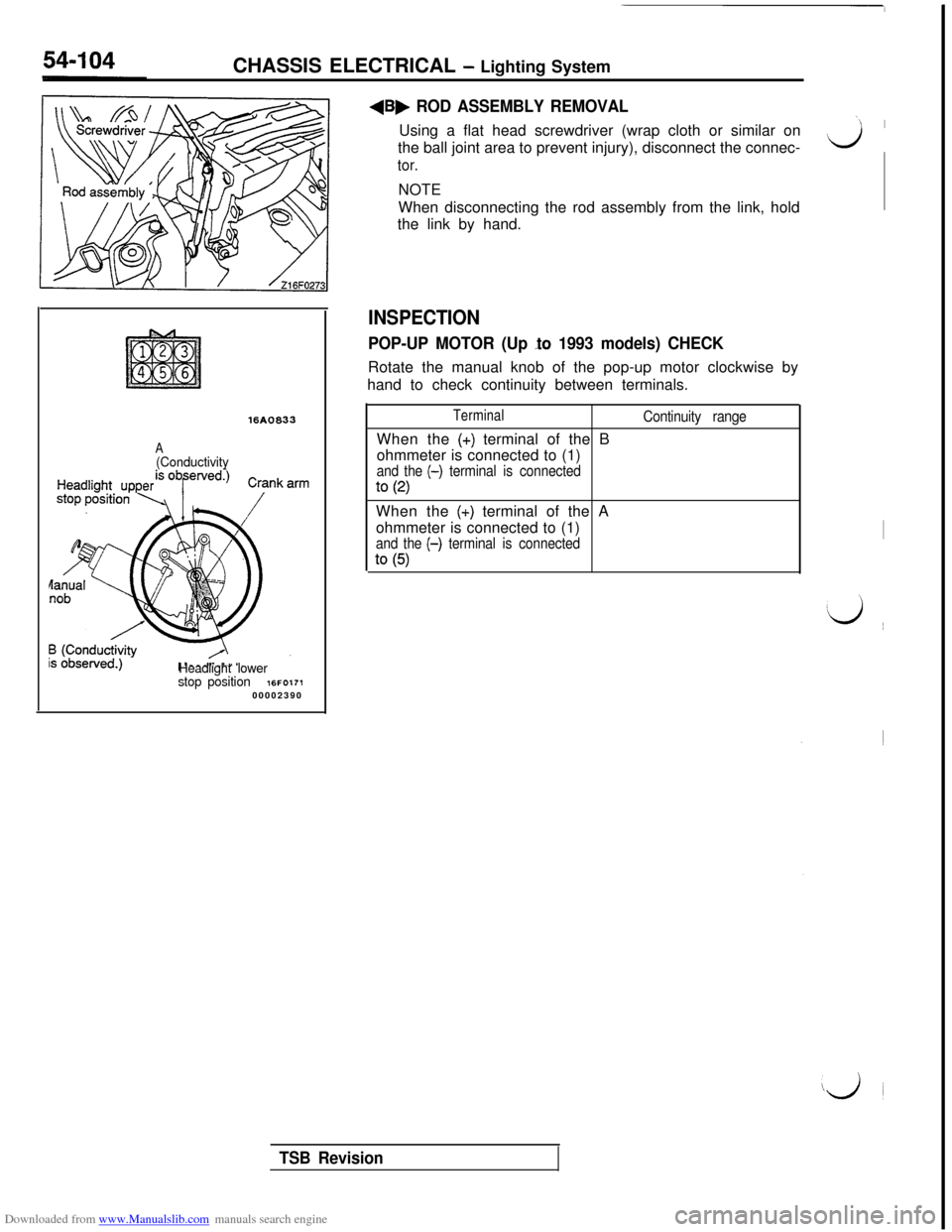
16A0833
A(Conductivity
Headlight lower
stop position
16FO17100002390
+B, ROD ASSEMBLY REMOVALUsing a flat head screwdriver (wrap cloth or similar on
the ball joint area to prevent injury), disconnect the connec-
tor.NOTE
When disconnecting the rod assembly from the link, hold
the link by hand.
INSPECTION
POP-UP MOTOR (Up lo 1993 models) CHECKRotate the manual knob of the pop-up motor clockwise by
hand to check continuity between terminals.
TerminalWhen the
(+) terminal of the B
ohmmeter is connected to (1)
and the (-) terminal is connected
to (2)
Continuity rangeWhen the
(+) terminal of the A
ohmmeter is connected to (1)
and the (-) terminal is connected
to (5)
‘1 I
Lj
I
‘d ~~
iji
TSB Revision
Page 608 of 738
Downloaded from www.Manualslib.com manuals search engine 54-112CHASSIS ELECTRICAL - Column SwitchCOLUMN SWITCH
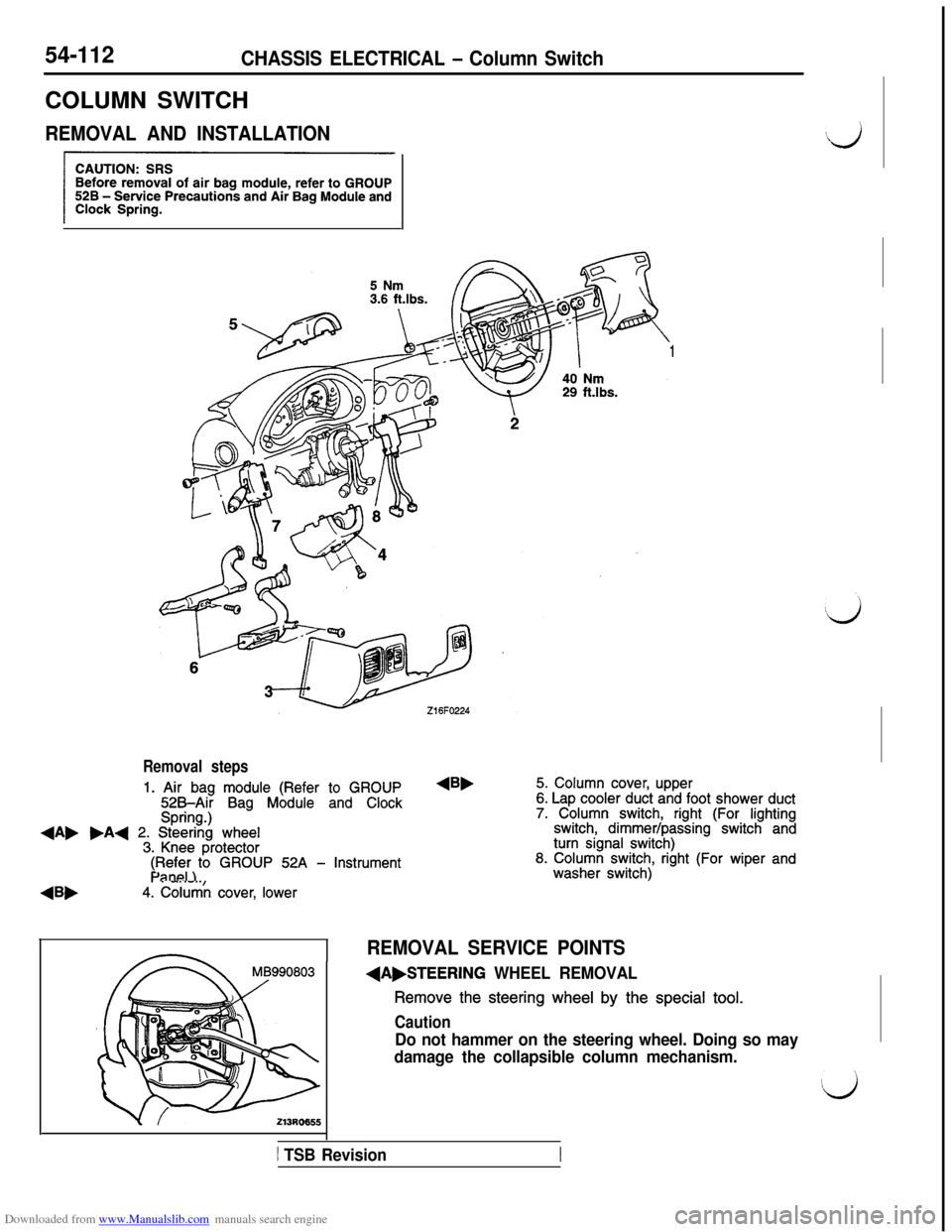
REMOVAL AND INSTALLATION
1
Removal steps
1. Air bag module (Refer to GROUP525Air Bag Module and ClockSpring.)+A, .A+ 2. Steering wheel3. Knee protector
4Bb
$F$i;)to GROUP 52A - Instrument
4. Column cover, lower
4B,5. Column cover, upper6. Lap cooler duct and foot shower duct7. Column switch, right (For lightingswitch, dimmer/passing switch andturn signal switch)8. Column switch, right (For wiper andwasher switch)
REMOVAL SERVICE POINTS
(A,STEERING WHEEL REMOVAL
Remove the steering wheel by the special tool.
Caution
Do not hammer on the steering wheel. Doing so may
damage the collapsible column mechanism.
1 TSB Revision
Page 609 of 738
Downloaded from www.Manualslib.com manuals search engine L
L
CHASSIS ELECTRICAL - Column Switch54-113
Front of vehicles
219FOlZ:
Mating mark-! !kU19FOOE
-
16FO237
16FO1:900002398
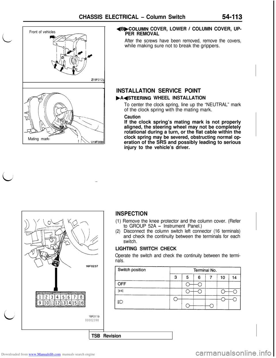
+B,COLUMN COVER, LOWER / COLUMN COVER, UP-
PER REMOVAL
After the screws have been removed, remove the covers,while making sure not to break the grippers.
INSTALLATION SERVICE POINT
.A(STEERING WHEEL INSTALLATION
To center the clock spring, line up the “NEUTRAL” markof the clock spring with the mating mark.
CautionIf the clock spring’s mating mark is not properly
aligned, the steering wheel may not be completely
rotational during a turn, or the flat cable within the
clock spring may be severed, obstructing normal op-eration of the SRS and possibly leading to serious
injury to the vehicle’s driver.
INSPECTION
(1) Remove the knee protector and the column cover. (Refer
(2)
to GROUP 52A - Instrument Panel.)
Disconnect the column switch left connector (16 terminals)
and check the continuity between the terminals for each
switch.
LIGHTING SWITCH CHECK
Operate the switch and check the continuity between the termi-
nals.
TSB Revision
Page 612 of 738
Downloaded from www.Manualslib.com manuals search engine 54-116CHASSIS ELECTRICAL - Horn
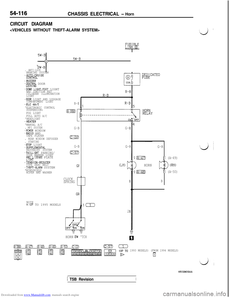
CIRCUIT DIAGRAM
c
5W-B;;-j
. ANTI-LOCKBRAKING SYSTEM*&$@lJUISE
.BUZZER*E;~CT~R~ DOOR
.DOME LIGHTsFOOT LIGHTAND IGNITION KEY
CYLINDER ILLUMINATION
LIGHT
.DOOR LIGHT AND LUGGAGECOMPARTMENT LIGHT.ELC 4A/T'ELECTRONIC CONTROL
SUSPENSION:
FOG LIGHT
FULL AUTO A/C
'HEADLIGHT
.HEATER
'MANUAL A/C
. MFI SYSTEM.POWER WINDOW.RADIO ANDTAPE PLAYER. REAR WINDOW DEFOGGER. STARTING.STOP LIGHT.SUPPLEMENTAL
RESTRAINT SYSTEM
.TAILLIGHT PARKING/SIDE MARKER LIGHTfJy;H;ICENSE PLATE
.TENSION-REDUCER
TYPE SEAT BELT
.THEFT-ALARM SYSTEM*WINDSHIELD
WIPER AND WASHER
NOTE::UP TO 1995 MODELS
R-B
(A-06X)
I
G-B
(c-02)
G-B
(c-57)
GF
CLOCK
SPRING
[
GE
;;&CATED
G-R
!(
2E=
HORNG-R
(LH)c
E
=
'TCH
G-R
l(A-47),l (A-49)
>HORN
l(A-48)"1 (A-50)
B
0 (A-47) oFa (A-49) ofiml (c-02)(c-57)=
1993 MODELS) (FROM 1994 MODELS)
El
‘J ’
HROSMOSAA
1 TSB RevisionI
Page 614 of 738
Downloaded from www.Manualslib.com manuals search engine 54-I 18CHASSIS ELECTRICAL - HornHORN SWITCH
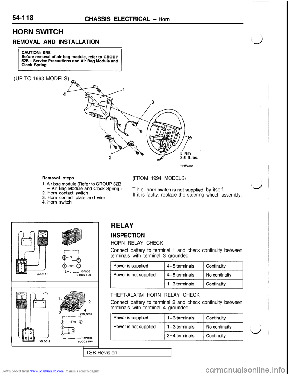
REMOVAL AND INSTALLATION(UP TO 1993 MODELS)
~
Y16FO207Removal steps
1. Air bag module (Refer to GROUP 528
(FROM 1994 MODELS)
- Air Bag Module and Clock Spring.)2. Horn contact switch3. Horn contact plate and wire4. Horn switchThe
horn switch is not supplied
If it is faulty, replace the steeringby itself.wheel assembly.i-.
-L 16FOO61200002400
RELAY
INSPECTION
HORN RELAY CHECK
Connect battery to terminal 1 and check continuity between
terminals with terminal 3 grounded.
~1
THEFT-ALARM HORN RELAY CHECK
Connect battery to terminal 2 and check continuity between
terminals with terminal 4 grounded.TSB Revision
Page 633 of 738
Downloaded from www.Manualslib.com manuals search engine CHASSIS ELECTRICAL - Radio and Tape Player
54-137 ~
L;
(c-(c-34)(c-57)00(D-36),(D-47)(F-06) FTC9
i
~~l~~[~!~~l~ -1
(F-33)(1czD2
Bfzi%$pJ q
HR14M03AB
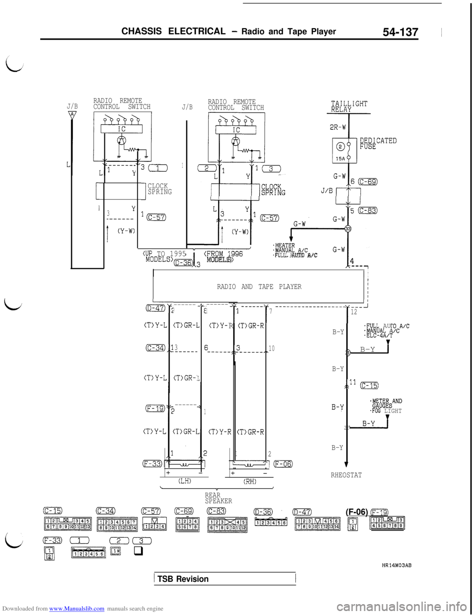
J/BRADIO REMOTE
CONTROL SWITCHJ/B
3Y
_------
!
(Y-W)
3(1
I
CLOCK
SPRING
I
*m
(UP TO 1995Y
(Fgyiiz/g~-
MODELS).FULL AUTO A/C4----1I
I
RADIO REMOTE
CONTROL SWITCH'T;Tk\IGHT
-T-2R-W
IRADIO AND TAPE PLAYERIIII
------1
(T)Y-
;-----.
@$* -=.------)E
(T>Y-L 2(T>GR-1
(c-34),>3E-----_
(T)Y-L(T>GR-'L
------11
(T)GR-I(T>Y-IR (T>GR-R22
+-
(LH)
- ------- ----------------------‘i1
r 1
7
r
12
i%A'CPR (T)GR-R.FULL AUB-Y.MANUAL I.ELC-4A/i
-;t_310_----_,,21> B-Y
B-Y
lhll (c-15)
B-YjE;EW&AND
.FOG LIGHT
B-Y12
4m7+-RHEOSTAT(RH)\Y/
REAR
SPEAKER
1 TSB Revision
Page 639 of 738
Downloaded from www.Manualslib.com manuals search engine CHASSIS ELECTRICAL - Radio and Tape Player54-143
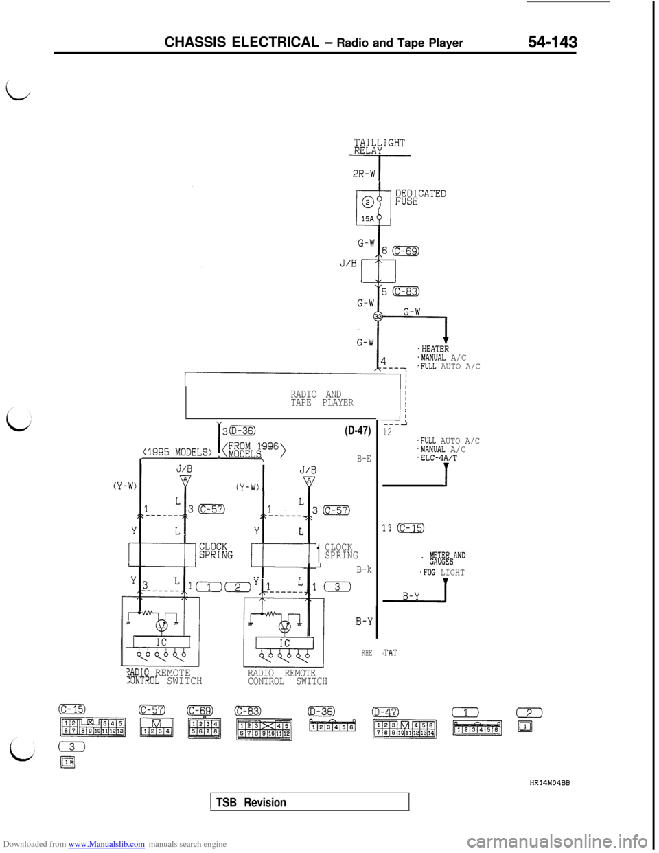
i@;X&GHT
-i-q-
.HEATER.MANUAL A/C.FULL AUTO A/C
RADIO AND
TAPE PLAYER
L1
------.
Y
t
L
. .i
t
(D-47)
B-E
1
CLOCK
SPRING
_IB-k
0
?ADIO REMOTE:ONTROL SWITCHRADIO REMOTE
CONTROL SWITCH
0-Y
RHE
3
---212.FULL AUTO A/C.MANUAL A/C.ELC-4A/T
1
.1 (c-15)
. ,$&AND
.FOG LIGHT
'TAT
HR14M04BB
TSB Revision
Page 645 of 738
Downloaded from www.Manualslib.com manuals search engine CHASSIS ELECTRICAL - Radio and Tape Player
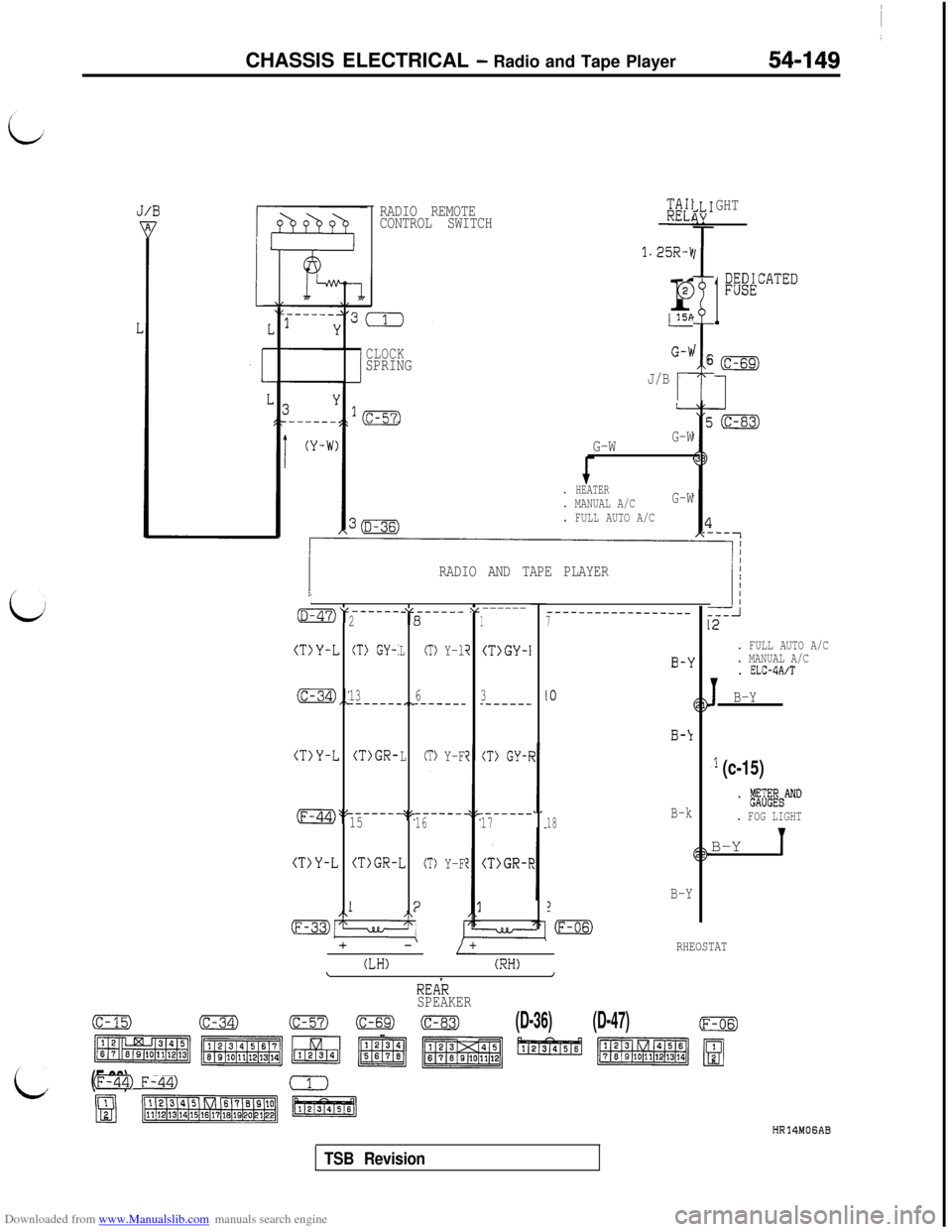
RADIO REMOTE
CONTROL SWITCHKK1
1.25R-kr
@
GHT
1
;@ATED
i
I6CLOCKSPRINGJ/B
r
. FULL AUTO A/C
G-WG-W
. HEATER. MANUAL A/CG-W
. FULL AUTO A/C
. MANUAL A/C
. ELC-4A/T
1B-Y RADIO AND TAPE PLAYER
i
I-----_OV -“,----_-v------281
(T)Y-LCT) GY-:LCT> Y-li(T>GY-I
_---_----___--____7
(c-34),: .,~1363_-----_------__------
(T>Y-L(T>GR-LCT> Y-F(T> GY-I
_----__------.(F-44)>? q'-.------15161718B-k
(T>Y-L 2(T)GR-ICT> Y-F(T>GR-F
B-Y1
-m
1:2/\
mz7LL/-I:
+-/+
(LH)(RH)\/
RHEOSTAT
,l (c-15)
. b&&&AND
. FOG LIGHTB-Y
1
REAR
SPEAKER
(c-15)(c-34)(c-57)00(D-36)(D-47)(F-06)
c ~~~~1~1~~~
(F-33)Fm)
mB(iisiEa
HR14MOGAB
TSB Revision
Page 682 of 738
Downloaded from www.Manualslib.com manuals search engine 54-186
CHASSIS ELECTRICAL - Radio and Tape Player
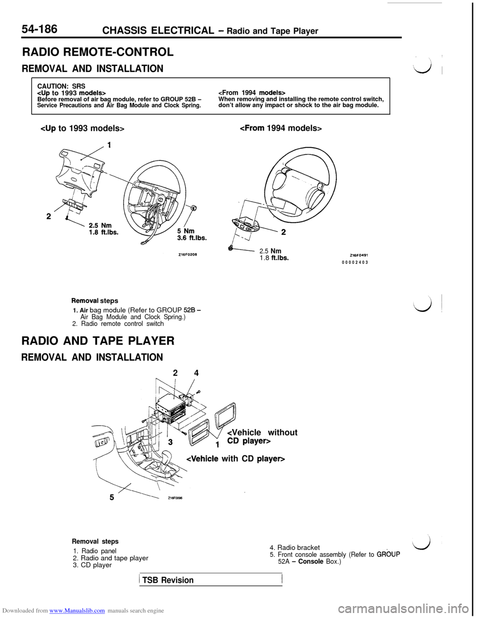
RADIO REMOTE-CONTROL
REMOVAL AND INSTALLATION
CAUTION: SRS
don’t allow any impact or shock to the air bag module.cup to 1993 models>
2.5 Nm1.8 ft.lbs.
Removai steps
1. Air bag module (Refer to GROUP
528 -Air Bag Module and Clock Spring.)
2. Radio remote control switchRADIO AND TAPE PLAYER
REMOVAL AND INSTALLATION2 4
Vehicle without
Z16FO49100002403
Removal steps
1. Radio panel2. Radio and tape player
3. CD player4. Radio bracket5. Front console assembly (Refer to GRbUP
52A - Console Box.)
1 TSB Revision
Page 686 of 738
Downloaded from www.Manualslib.com manuals search engine CHASSIS ELECTRICAL - Radio and Tape Player
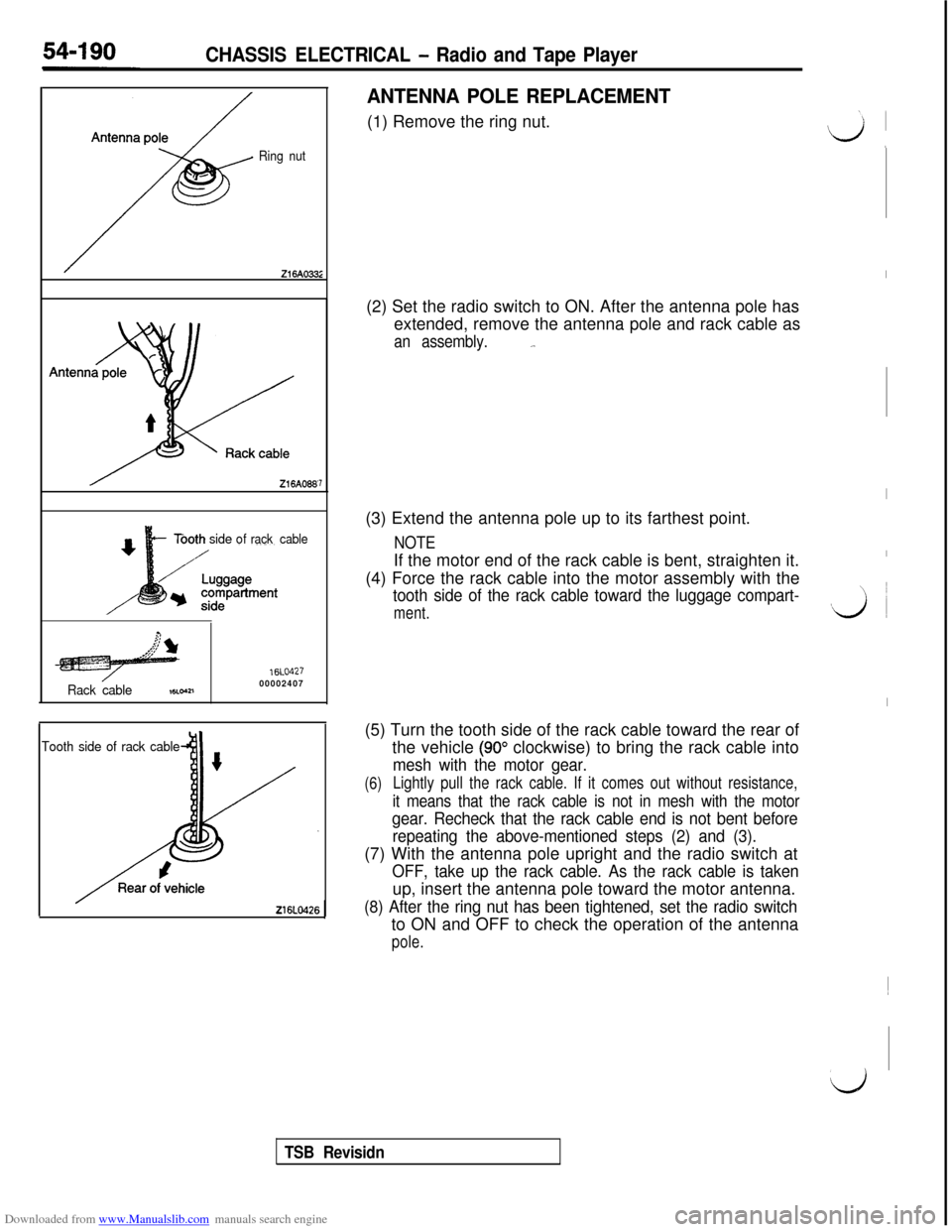
Ring nut
Tbothsideofrack cable
Rack cable
16LO42700002407,8Loa1
7
Tooth side of rack cable
ANTENNA POLE REPLACEMENT(1) Remove the ring nut.
(2) Set the radio switch to ON. After the antenna pole has
extended, remove the antenna pole and rack cable as
an assembly._.(3) Extend the antenna pole up to its farthest point.
NOTEIf the motor end of the rack cable is bent, straighten it.
(4) Force the rack cable into the motor assembly with the
tooth side of the rack cable toward the luggage compart-
ment.(5) Turn the tooth side of the rack cable toward the rear of
the vehicle
(90” clockwise) to bring the rack cable into
mesh with the motor gear.
(6)Lightly pull the rack cable. If it comes out without resistance,
it means that the rack cable is not in mesh with the motor
gear. Recheck that the rack cable end is not bent before
repeating the above-mentioned steps (2) and (3).(7) With the antenna pole upright and the radio switch at
OFF, take up the rack cable. As the rack cable is takenup, insert the antenna pole toward the motor antenna.
(8) After the ring nut has been tightened, set the radio switchto ON and OFF to check the operation of the antenna
pole.
I
I
I
vi ~
I~
d
TSB Revisidn