Power transistor MITSUBISHI 3000GT 1994 2.G Owner's Guide
[x] Cancel search | Manufacturer: MITSUBISHI, Model Year: 1994, Model line: 3000GT, Model: MITSUBISHI 3000GT 1994 2.GPages: 738, PDF Size: 35.06 MB
Page 301 of 738
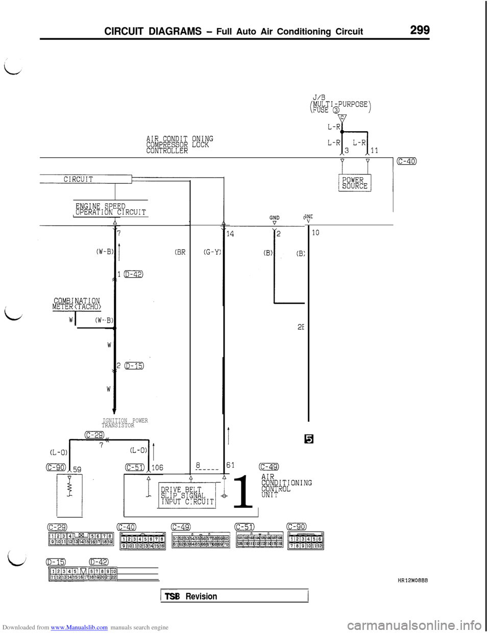
Downloaded from www.Manualslib.com manuals search engine CIRCUIT DIAGRAMS - Full Auto Air Conditioning Circuit299
AIR CONDITCOMPRESSORCONTROLLER
ONINGLOCK
J/B
(MULTI-PURPOSEFUSE @JC
L-R
h
L-RL-R311
ENGINE SPEEDOPERATION CIRCUIT
COMBINATION~METE~/TACH~~-
(BR
IGNITION POWERTRANSISTOR
8_-----
1 p&,-1
(G-Y)
I
E-
;NCV
2E%
;1(c-49)1
AIRE8/~Cl~~ONING
UNIT
10
(c-29)(c-40)(c-49)(c-51)(c-90)
pjz$zmg:,-1
/
kv/(D-15)(D-42)
p?lRq-1HR12MOEBB
r--TSB Revision
Page 302 of 738
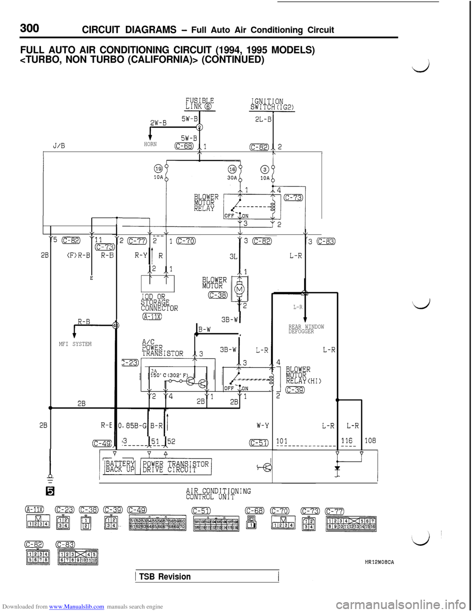
Downloaded from www.Manualslib.com manuals search engine 300CIRCUIT DIAGRAMS - Full Auto Air Conditioning Circuit
FULL AUTO AIR CONDITIONING CIRCUIT (1994, 1995 MODELS)
i
2W-B2L-B
15W-BJ/BHORN(c-68) ,,lI(c-82),, 2,\bI
\/
"5 (c-82)"
28(F)R-B
E
R-B
MFI SYSTEM
02B
28R-E
(c-49:
I15
13I, 151 52.-----_ __(c-51)
v 0--
1 /%Z”BpYI (EKE RfiF8iaToRj
T
\I \IJV
‘20 2-- 10D'3 (c-83)
jL-R
,,2 ,,l\ /\
IOD ORSTORAGECONNECTORL-R
(A-11X)3B-WI
,2B-W1
A/CPOWERTRANSISTOR,,3
m-------.-2A------__1\I \,\/OFF-,;ON"2 "428"1"12B
W-Y
TREAR WINDOW
DEFOGGER
L-R
4
I
BkPKRRELAYCHI)
2m
0
L-RL-R
101116108------___------ -___
Lj
AIR CONDITIONINGCONTROL UNIT
HR12MOECA
1 TSB Revision
Page 309 of 738
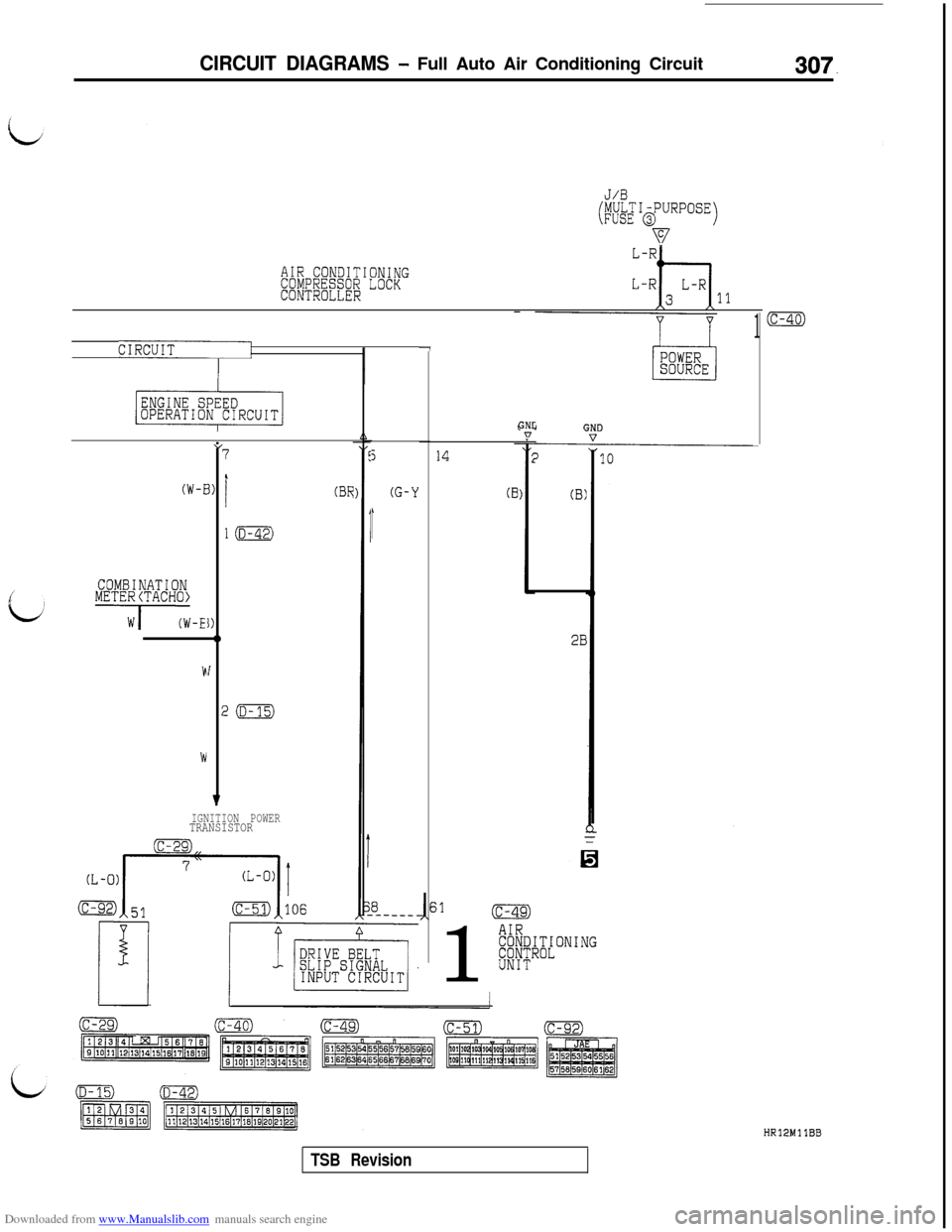
Downloaded from www.Manualslib.com manuals search engine CIRCUIT DIAGRAMS - Full Auto Air Conditioning Circuit307.
J/B
(MULTI-PURPOSEFUSE @)
v
AIR CONDITIONINGCOMPRESSOR LOCKCONTROLLER11
1
CIRCUITpj-7
(W-E
cvCOMBINATIONMETE~iTACH~~-I”
r
1)
I)-lb
I
;
v
7
I
l(D-42)
!m
IGNITION POWERTRANSISTOR
(BR
5
(G-Y
,
14
(B
GNL:n
(B)
2B1
AIR#/;~;[ONING
UNIT
(c-40)
HR12MllBB
TSB Revision
Page 310 of 738
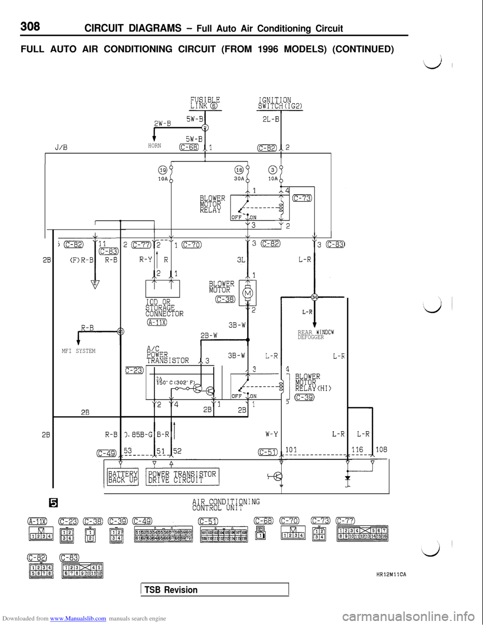
Downloaded from www.Manualslib.com manuals search engine CIRCUIT DIAGRAMS - Full Auto Air Conditioning CircuitFULL AUTO AIR CONDITIONING CIRCUIT (FROM 1996 MODELS) (CONTINUED)
\
‘d ~
2W-B2L-B
5W-B
J/0HORN(c-68) ,,l(c-82),, 2
R-B
MFI SYSTEM
2B
R-E
1
6310A
4
iFBR(c-73)
RELAY
\,&\/T- \I
J2(c-77)2-- 10"3 (c-83)
IR-Y Ri,2 ,,lI\ /\
IOD ORSTORAGECONNECTOR
(A-11X)
L-R
t
34
L-R
A/CPOWERTRANSISTOR ,.33B-WL-R
c-23),\ 3I\2A- - - - - - - -,
\,\/OFF-:,ON
"2 "4"12B" 12B
).85B-G B-RW-Y
(c-51)
REAR WiNDOWDEFOGGER
L-K
4
I
k%"RELAYCHI)
,m
L-RL-R
101116108-
AIR CONDITIONINGCONTROL UNIT
(c-se)0HRlPMllCA
1 TSB Revision
Page 478 of 738
Downloaded from www.Manualslib.com manuals search engine ENGINE ELECTRICAL - lanition Svstem
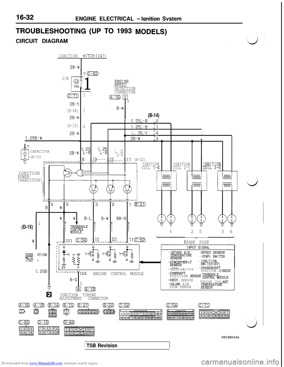
TROUBLESHOOTING (UP TO 1993MODELS)CIRCUIT DIAGRAM
IGNITIONhiITCH(IG1)
2B-X
7m
1
J/B
c
015A
(c-71)
2B-Y
(D-44)
2B-W
(D-15)
2B-W
1.25B-W
@%t”DETECTION
CONNECTOR
5
5
(B-14)
1.25L-R,,2
41.25L-B;,l
,,1. 25L-Y;,4I
2B-W23_
y;'$1. 25L-Y
A6 ,P-----,\22-----,,ll(B-22) /\,h,\IGNITION
IGNITIONCOIL1-4COIL2-5-r--
CAPACITOR
(B-15)2B-W
1/IGNITION IPOWERTRANSISTOR!rl
2
4TION
)
(D-15)
3%(TAC
42 5
3 6
”
SPARK PLUG
1.25B
IIIIIIII1IL
“-6% “-6 “-4%4;ig;f;HERIC.IGNITIONSWITCHtST)/ 5vv.(CTP) SWITCH.CRANKSHAFT
.CAMSHAFTPOSITION SEENGINE CONTROL MODULEPOSITION SENSOR';#$;~L;oc.KNOCK SENSOR.VOLUME AIR*ENGINE COOL
FLOW SENSOR;ED&f$AT"RE
:NSOR
IULE:ANT
IGNITION TIMING
ADJUSTMENT CONNECTOR
HR03MOOAA
1 TSB Revision
Page 480 of 738
Downloaded from www.Manualslib.com manuals search engine 16-34ENGINE ELECTRICAL - Ignition System
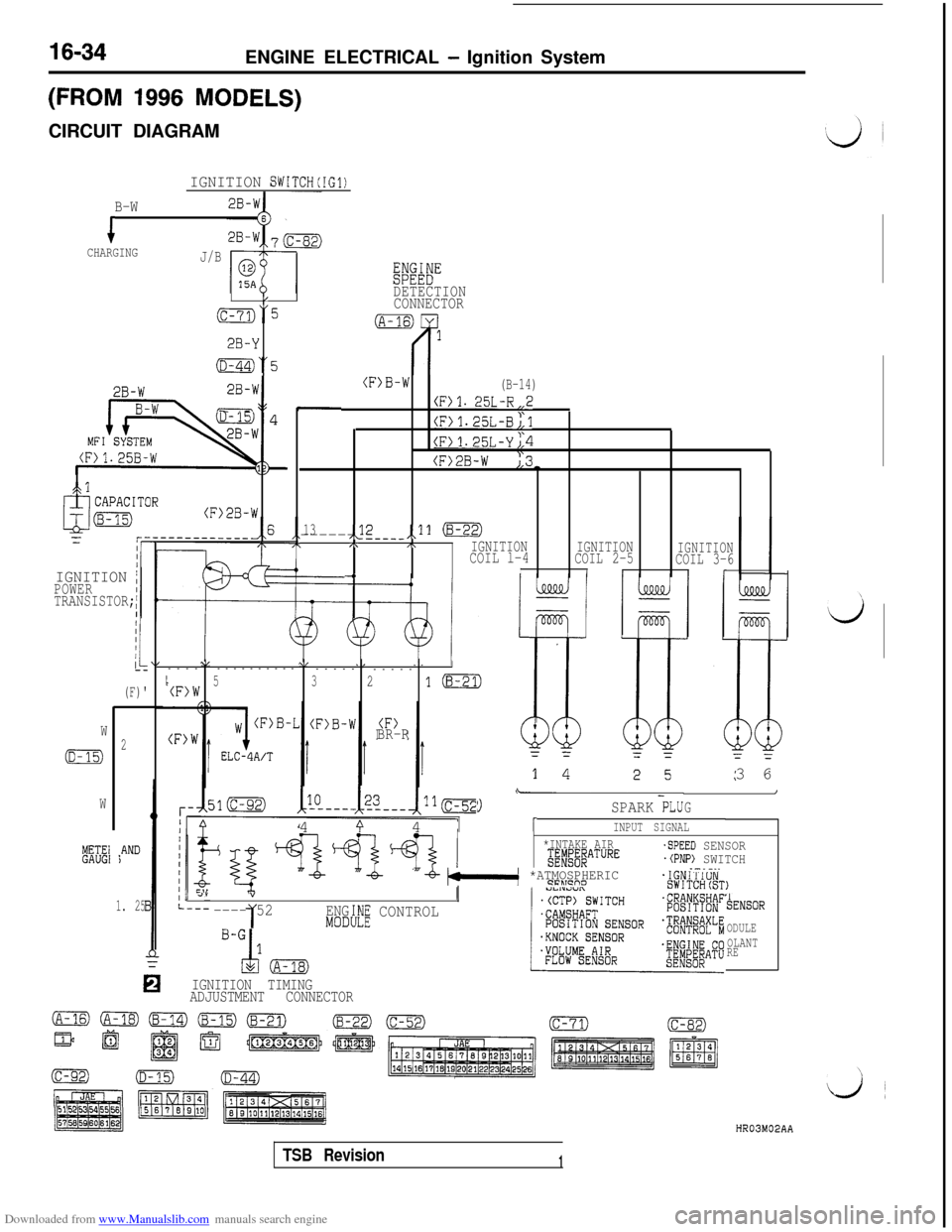
(FROM 1996 MODELS)CIRCUIT DIAGRAM
IGNITION SWITCH(IG1)
B-W
iCHARGINGJ/B
Eiwi"
/DETECTION
(c-73)“5CONNECTOR
2B-Y
(D-44)“5
2B-W-I
2B-W
MFILS - --
(F>B-W(B-14)
(F)l. 25L-R,,2
(F)1.25L-B;,l
(F>1.25L-Yj,4
(F>2B-W ),3-
.
13,<2------ ---__,,11 (8-22),\,\IGNITIONCOIL l-4IGNITION
COIL 2-5IGNITIONCOIL 3-6-4III(r
,cl
(F>2B-W
IGNITION /POWER
TRANSISTOR;
I
(F)'
\I\/,I--------------
-----
-----
I5(F)W321m
BR-RW
(D-15)2
W
METE1GAUGI*AND)3 6
\-I
G9SPARK PLU4
9 41INPUT SIGNAL
*INTAKE AIRg;#j#ATURE
"-b- bkl *ATMOSPHERIC9FLTcno
-SPEED SENSOR.(PNP) SWITCH.-.-..
, 4””
---- 521ENG:h!E CONTROLMODI
TENSOR
ODULE
OLANT
RE
IGNITION TIMING
ADJUSTMENT CONNECTOR
1. 25
HR03M02AA
TSB Revision1
Page 481 of 738
Downloaded from www.Manualslib.com manuals search engine i;ENGINE ELECTRICAL
- Ignition System16-35
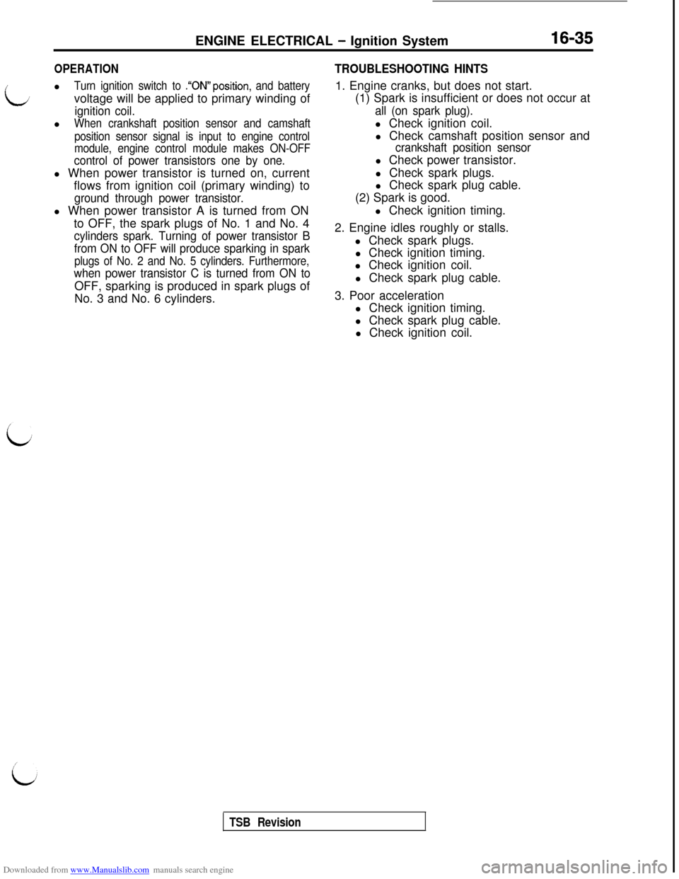
OPERATIONl
Turn ignition switch to .“ON”position, and batteryvoltage will be applied to primary winding of
ignition coil.l
When crankshaft position sensor and camshaft
position sensor signal is input to engine control
module, engine control module makes ON-OFF
control of power transistors one by one.l When power transistor is turned on, current
flows from ignition coil (primary winding) to
ground through power transistor.l When power transistor A is turned from ON
to OFF, the spark plugs of No. 1 and No. 4
cylinders spark. Turning of power transistor B
from ON to OFF will produce sparking in spark
plugs of No. 2 and No. 5 cylinders. Furthermore,
when power transistor C is turned from ON toOFF, sparking is produced in spark plugs of
No. 3 and No. 6 cylinders.
TROUBLESHOOTING HINTS1. Engine cranks, but does not start.
(1) Spark is insufficient or does not occur at
all (on spark plug).l Check ignition coil.
l Check camshaft position sensor and
crankshaft position sensorl Check power transistor.
l Check spark plugs.
l Check spark plug cable.
(2) Spark is good.
l Check ignition timing.
2. Engine idles roughly or stalls.
l Check spark plugs.
l Check ignition timing.
l Check ignition coil.
l Check spark plug cable.
3. Poor acceleration
l Check ignition timing.
l Check spark plug cable.
l Check ignition coil.
TSB Revision
Page 491 of 738
Downloaded from www.Manualslib.com manuals search engine ENGINE ELECTRICAL - Ignition System16-45 l
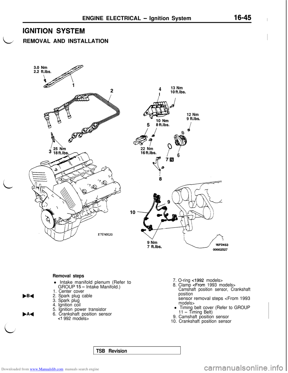
IGNITION SYSTEM
LREMOVAL AND INSTALLATIONI
i
27EN0520
413 NmIlOft.lbs.
d
12 Nm
9 ft.lbs.
22 Nm16ftAbs.B678
W1
,A4
Removal stepsl Intake manifold plenum (Refer to
GROUP
1.5 - Intake Manifold.)1. Center cover
2. Spark plug cable
3. Spark plug
4. Ignition coil
5. Ignition power transistor
6. Crankshaft position sensor
cl 992 models>9 Nm
7
ft.lbs.u 16FO453
00662527
7. O-ring cl992 models>
8. Clamp
positionsensor removal steps
11 - Timing Belt)
9. Camshaft position sensor
10. Crankshaft position sensor
TSB Revision
Page 494 of 738
Downloaded from www.Manualslib.com manuals search engine 16-48ENGINE ELECTRICAL - lanition Svstem
\/27EL0086
/DEL0087INSPECTION
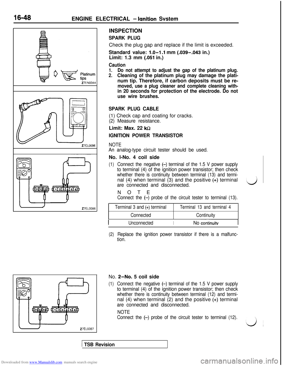
SPARK PLUGCheck the plug gap and replace if the limit is exceeded.
Standard value:
1.0-l .l mm (.039-.043 in.)
Limit: 1.3 mm
(.051 in.)
Caution
1.Do not attempt to adjust the gap of the platinum plug.
2.Cleaning of the platinum plug may damage the plati-num tip. Therefore, if carbon deposits must be re-
moved, use a plug cleaner and complete cleaning with-
in 20 seconds for protection of the electrode. Do not
use wire brushes.
SPARK PLUG CABLE(1) Check cap and coating for cracks.
(2) Measure resistance.Limit: Max. 22
ksZ
IGNITION POWER TRANSISTOR
NOTE
An analog-type circuit tester should be used.No. l-No. 4 coil side
(1)Connect the negative (-) terminal of the 1.5 V power supply
to terminal (4) of the ignition power transistor; then check
whether there is continuity between terminal (13) and termi-nal (4) when terminal (3) and the positive
(+) terminal
are connected and disconnected.NOTE
Connect the (-) probe of the circuit tester to terminal (13).
Terminal 3 and (+) terminal
ConnectedTerminal 13 and terminal 4
Continuity
IUnconnectedINo continuitv
(2)Replace the ignition power transistor if there is a malfunc-
tion.No. ~-NO. 5 coil side
(1)Connect the negative (-) terminal of the 1.5 V power supply
to terminal (4) of the ignition power transistor; then check
whether there is continuity between terminal (12) and termi-nal (4) when terminal (2) and the positive
(+) terminal
are connected and disconnected.
NOTE
Connect the (-)
probe of the circuit tester to terminal (12).
[ TSB Revision
Page 495 of 738
Downloaded from www.Manualslib.com manuals search engine ENGINE ELECTRICAL b Ignition System16-49
27EL0089
Z7ELOOQO
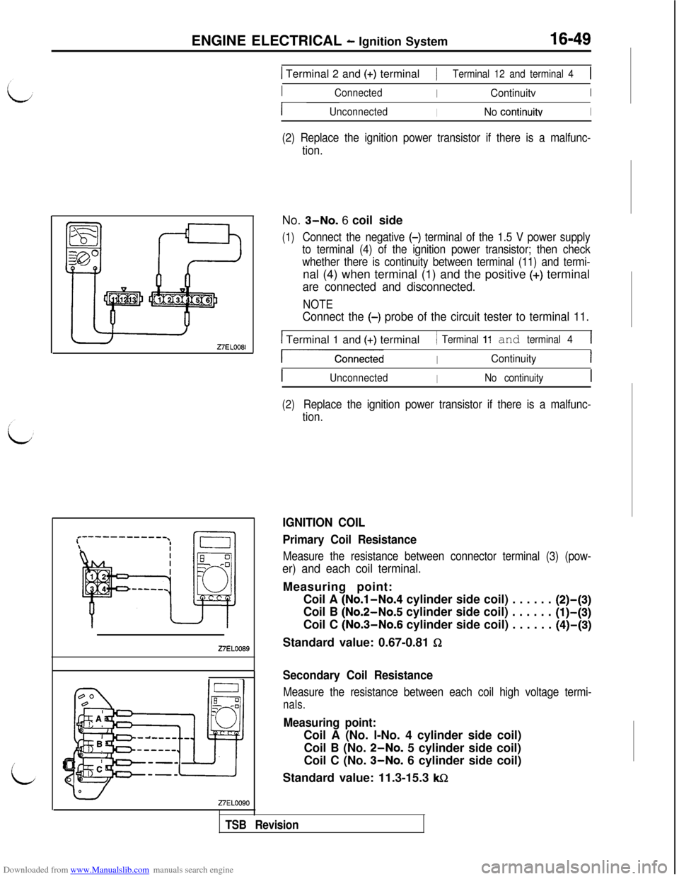
1 Terminal 2 and (+) terminal/Terminal 12 and terminal 41
IConnectedIContinuitvI
IUnconnectedINo continuitvI
(2) Replace the ignition power transistor if there is a malfunc-
tion.No. ~-NO. 6 coil side
(1)Connect the negative (-) terminal of the 1.5 V power supply
to terminal (4) of the ignition power transistor; then check
whether there is continuity between terminal (11) and termi-nal (4) when terminal (1) and the positive
(+) terminal
are connected and disconnected.
NOTE
Connect the (-) probe of the circuit tester to terminal 11.
I Terminal 1 and (+) terminal/ Terminal 11 and terminal 41
-ConnectedIContinuityI
IUnconnectedINo continuityI
(2)Replace the ignition power transistor if there is a malfunc-
tion.
IGNITION COIL
Primary Coil Resistance
Measure the resistance between connector terminal (3) (pow-
er) and each coil terminal.Measuring point:
Coil A
(No.l-No.4 cylinder side coil) . . . . . . (2)-(3)Coil B (No.2-No.5 cylinder side coil) . . . . . .
(l)-(3)Coil C (No.3-No.6 cylinder side coil) . . . . . .
(4)-(3)Standard value: 0.67-0.81
Sz
TSB Revision
Secondary Coil Resistance
Measure the resistance between each coil high voltage termi-
nals.
Measuring point:Coil A (No. l-No. 4 cylinder side coil)
Coil B (No. ~-NO. 5 cylinder side coil)
Coil C (No. ~-NO. 6 cylinder side coil)
Standard value: 11.3-15.3
Wz