turn signal MITSUBISHI 3000GT 1994 2.G Service Manual
[x] Cancel search | Manufacturer: MITSUBISHI, Model Year: 1994, Model line: 3000GT, Model: MITSUBISHI 3000GT 1994 2.GPages: 738, PDF Size: 35.06 MB
Page 512 of 738
Downloaded from www.Manualslib.com manuals search engine 54-16CHASSIS ELECTRICAL - Meters and Gauges
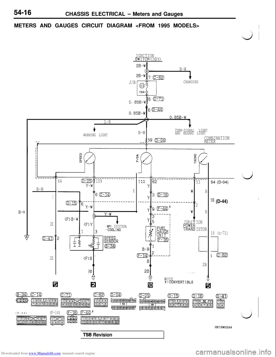
METERS AND GAUGES CIRCUIT DIAGRAM
IGNITIONSWITCH(IG1)
B-W
J/B
CHARGING
\,
0. 85B-W“' -
tO.B5B-Ws(D-44)
B-1
O.B5B-W
L-RI
--r
tB-WTURN-SIGNAL LIGHT
WARNING LIGHTAND HAZARD LIGHT
--,,59 (D-04)COMBINATION
METER
/\
B-W
I
2E
2E(F:
64(D-C
Y
\L
-W
\:
---.
-W
13
)Y
)B '
0
2Bn=
-------------____109
ES(c-14)
--------------___
.MFI SYSTEMIGN:
R3
(B-34) (c-14)(c-71)
m m m z ~~~~5&4
60161(6216~64165166167(D-44)
(F-14)(Fm (ml'
NOTE4::CONVERTIBLE
-..I
-----53
B
2
B
ION
ISTOR
i
2B
‘d54 (D-04)
I6 (D-44)I
16 (c-71)
1
j(c-82)
TSB Revision
Page 518 of 738
Downloaded from www.Manualslib.com manuals search engine CHASSIS ELECTRICAL - Meters and Gauges
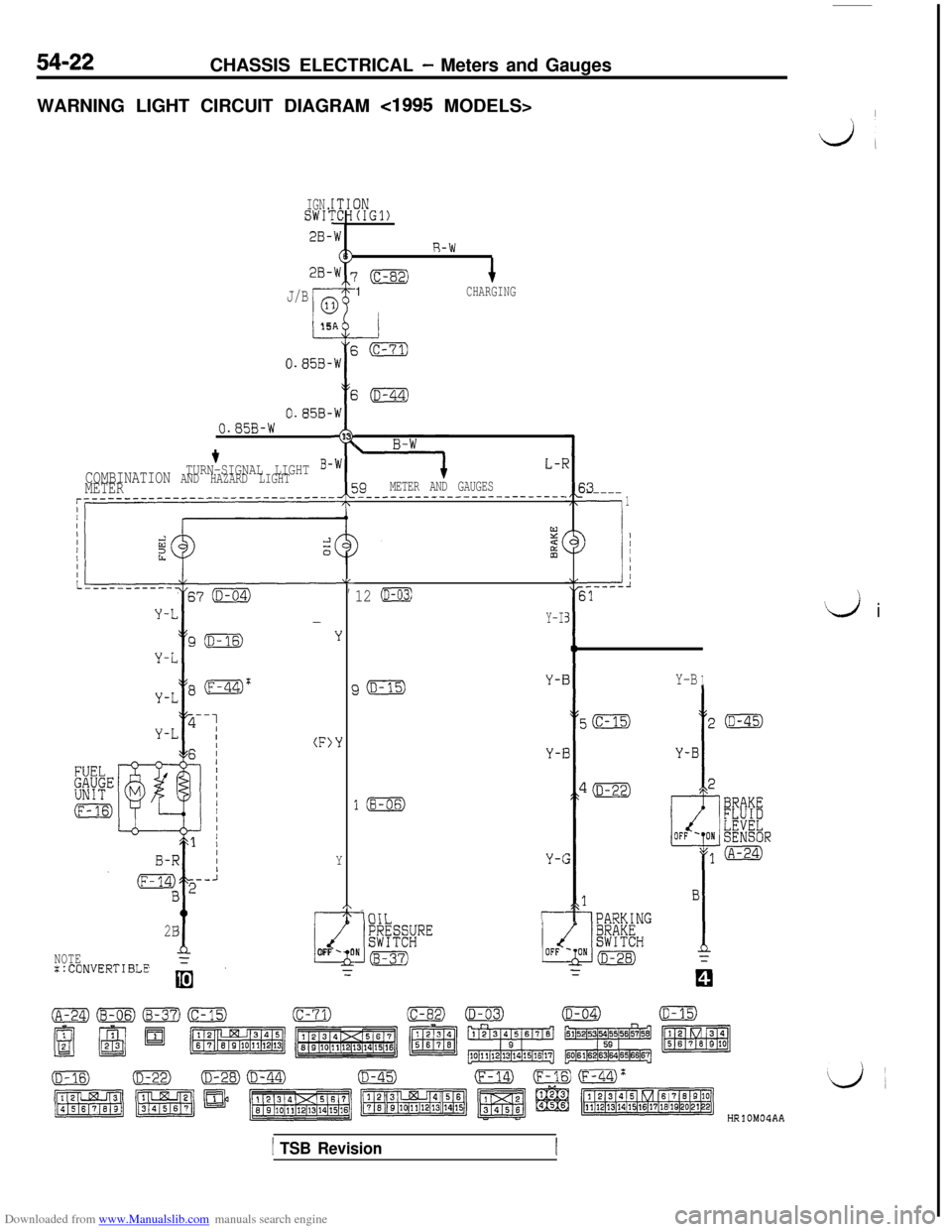
WARNING LIGHT CIRCUIT DIAGRAM
cl995 MODELS>I
dl
IGN.SWI:IN(IGl)
2B-
2B-
R-W
‘(c-82)1CHARGINGJ/B
I-15
0.858-AEW
E
,W
I
13
,W
5;(D-44)
0.858-0.85B-W
L-T
39METER AND GAUGES_______--_----------------
+TURN-SIGNAL LIGHT B-COMBINATION AND HAZARD LIGHTMETER$3-----
-.
1
--i
) ;
.-----l31
LL,
Y
‘Y
Y
,\1T-
2B
dNOTEFLOFF -0
::CONVERTIBLE=
‘d i
12 (D-03)
Y-I
Y-BIJ(D-15)Y-i
Y-i
l(B-06)
Y-C
-iniTr--
HRlOM04AA
1 TSB Revision
Page 520 of 738
Downloaded from www.Manualslib.com manuals search engine 54-24CHASSIS ELECTRICAL - Meters -and Gauges
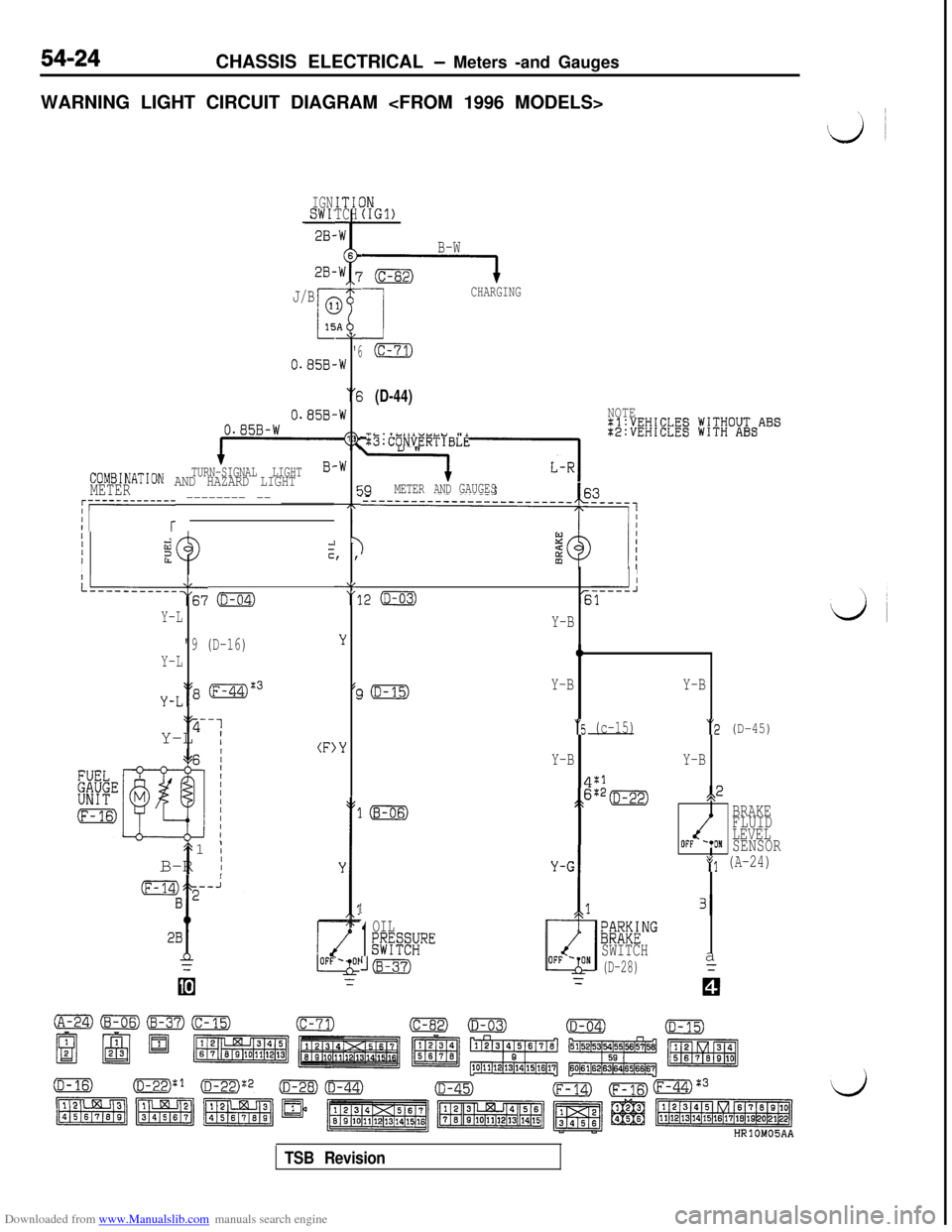
WARNING LIGHT CIRCUIT DIAGRAM
IGNSWI'28-ITICTCH
2B-
J/B
0.85B-
0.858,0.85B-W
TURN-SIGNAL LIGHTCOMBINATION AND HAZARD LIGHTMETER
AL
'6.W
“6
-W
13
-W
cc7T,
I y, ,
‘8"11
;;i;EW;EElg jV;V;O&ABS
:B:CONVERTIBLE
j9METER ANDGAUGES~r-----------r -------- -- _______
IIIiizzIcI
L--------‘:67 o
Y-L
"9 (D-16)
Y-L
y-L‘18 (F-44)%3‘y-1
Y-L
I(F)
t1
;B-R
I
IN(IGl)
B-W
G----l
1
CHARGING
(c-71)
(D-44)NOTE
II
.2 (D-03)-----J61
LL
'3
Y
(c
,Y
Y-B
0
Y-BY-B
“5 (c-15)“2 (D-45)
Y-BY-B
4:1
;>6:*=s,2
BRAKE
FLUID
LEVEL
OFF '*ONSENSOR
*(I (A-24)
1
1
OIL;@SRE
((B-37)
/
131
;~M&NG
SWITCH
(D-28)a
TSB Revision
Page 521 of 738
Downloaded from www.Manualslib.com manuals search engine CHASSIS ELECTRICAL - Meters and Gauaes
i
L/
IGNISW17
2B-\1
28-l
2B-\I
2B-‘1
(A-67)
2B-Y
STARTING
SUPPLEMENTAL
~E~&~J$NT
----------.+OFFIN
13
i
G-B
3(c-02) 3--
G-B
1.25B-Y
+MFI SYSTEM
'(D-15)DIODE
1.25B-Yu
I
IGNITIONSWITCH(IG1)
J/B
ml
0
15A“6
(D-44)
0.85B-W
B-W(130.85B-W
METER AND
GAUGESB-WTURN-SIGNAL LIGHT
r----+$30AND HAZARD LIGHT
i B-W
9
i;yEKNATION
(D-04)
HRlOM05AB
TSB Revision
Page 531 of 738
Downloaded from www.Manualslib.com manuals search engine CHASSIS ELECTRICAL - Lighting System
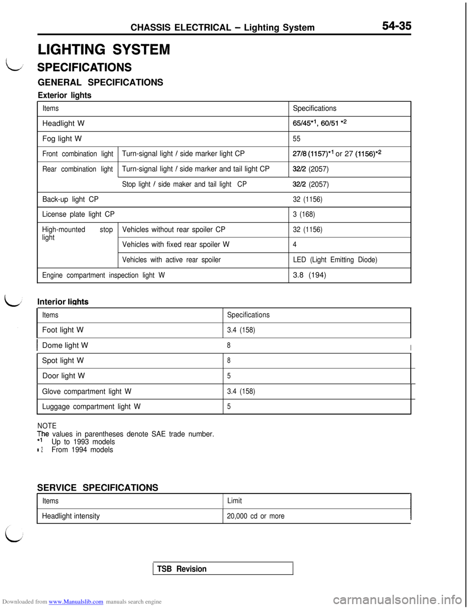
LIGHTING SYSTEM
54-35
L/ SPECIFICATIONSGENERAL SPECIFICATIONS
Exterior lights
ItemsSpecificationsHeadlight W
65/45*‘, 60151 *2Fog light W
55
Front combination light
Turn-signal light / side marker light CP27/8 (1157)” or 27 (1156)*2
Rear combination lightTurn-signal light / side marker and tail light CP32/2 (2057)
Stop light / side maker and tail lightCP32/2 (2057)
Back-up light CP
32 (1156)
License plate light CP3 (168)
High-mountedstop
Vehicles without rear spoiler CP32 (1156)
light
Vehicles with fixed rear spoiler W4
Vehicles with active rear spoiler
Engine compartment inspection light WLED (Light Emitting Diode)3.8 (194)
Interior
lights
ItemsFoot light WSpecifications
3.4 (158)
IDome light W8ISpot light W
8Door light W
5
Glove compartment light W
Luggage compartment light W3.4 (158)
5
NOTE
;he values in parentheses denote SAE trade number.
Up to 1993 models
l 2From 1994 modelsSERVICE SPECIFICATIONS
ItemsLimitI
Headlight intensity
I
20,000 cd or moreI
TSB Revision
Page 552 of 738
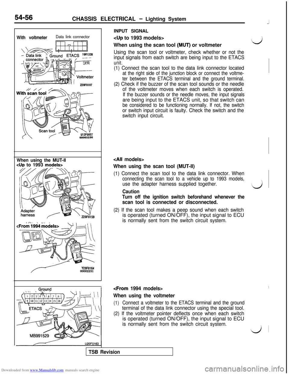
Downloaded from www.Manualslib.com manuals search engine INPUT SIGNALWith voltmeterData link connector
Ii ri7-11
When using the scan tool (MUT) or voltmeter‘d
Using the scan tool or voltmeter, check whether or not the
input signals from each switch are being input to the ETACS
unit.
54-56CHASSIS ELECTRICAL - Lighting System
(1) Connect the scan tool to the data link connector located
at the right side of the junction block or connect the voltme-
ter between the ETACS terminal and the ground terminal.
(2) Check if the buzzer of the scan tool sounds or the needle
of the voltmeter moves when each switch is operated.
If the buzzer sounds or the needle moves, the input signalsare being input to the ETACS unit, so that switch can
be considered to be functioning normally. If not, the switch
or switch input circuit is faulty. Check the switch and the
switch input circuit.
When using the MUT-II
CUP to 1993 models>
Y2OFO16400002231,
0,@y.m$
( 1 1 1 2 1; 1 4% 16 1 7 1 8 / 1
’ 1-d \ \ 1
~~~4i10illi12i13illi15i16v~~~1 \ \ 1U2OFO163
When using the scan tool (MUT-II)
(1) Connect the scan tool to the data link connector. When
connecting the scan tool to a vehicle up to 1993 models,
use the adapter harness supplied together.‘dCaution
Turn off the ignition switch beforehand whenever the
scan tool is connected or disconnected.
(2) If the scan tool makes a peep sound when each switchis operated (turned ON/OFF), the input signal to ECU
is normally sent from the switch circuit system.
When using the voltmeter
(1)Connect a voltmeter to the ETACS terminal and the ground
terminal of the data link connector using the special tool.
(2) If the voltmeter pointer deflects once when each switchis operated (turned ON/OFF), the input signal to ECU
is normally sent from the switch circuit system.
do
TSB Revision
Page 574 of 738
Downloaded from www.Manualslib.com manuals search engine 54-78CHASSIS ELECTRICAL - Lighting System
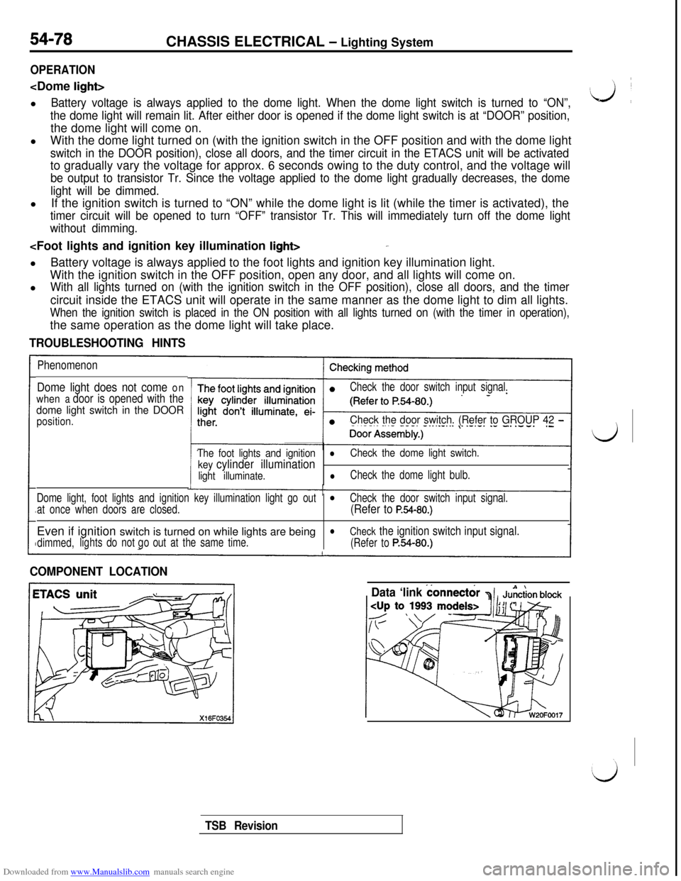
OPERATION
Battery voltage is always applied to the dome light. When the dome light switch is turned to “ON”,
the dome light will remain lit. After either door is opened if the dome light switch is at “DOOR” position,the dome light will come on.
lWith the dome light turned on (with the ignition switch in the OFF position and with the dome light
switch in the DOOR position), close all doors, and the timer circuit in the ETACS unit will be activatedto gradually vary the voltage for approx. 6 seconds owing to the duty control, and the voltage will
be output to transistor Tr. Since the voltage applied to the dome light gradually decreases, the dome
light will be dimmed.lIf the ignition switch is turned to “ON” while the dome light is lit (while the timer is activated), the
timer circuit will be opened to turn “OFF” transistor Tr. This will immediately turn off the dome light
without dimming.
With the ignition switch in the OFF position, open any door, and all lights will come on.
l
With all lights turned on (with the ignition switch in the OFF position), close all doors, and the timercircuit inside the ETACS unit will operate in the same manner as the dome light to dim all lights.
When the ignition switch is placed in the ON position with all lights turned on (with the timer in operation),the same operation as the dome light will take place.
TROUBLESHOOTING HINTS
Phenomenon
Dome light does not come on
when
a door is opened with the
dome light switch in the DOOR
position.
Check the door switch input signal.
Check the door switch. (Refer to GROUP 42 -
The foot lights and ignitionl
key cylinder illumination
Check the dome light switch.
light illuminate.
lCheck the dome light bulb.
Dome light, foot lights and ignition key illumination light go out
l
at once when doors are closed.Check the door switch input signal.(Refer to P.54-80.)Even if ignition switch is turned on while lights are being
l
dimmed,lightsdo notout at the same time.
Check the ignition switch input signal.
go
(Refer toP.54-80.)
COMPONENT LOCATION
Data ‘link
connect&
TSB Revision
Page 576 of 738
Downloaded from www.Manualslib.com manuals search engine With voltmeterData link connector
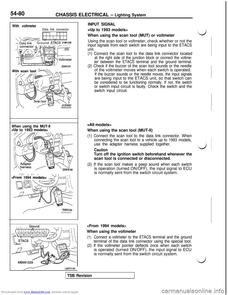
’‘:’ ’ ’- Data linkGround ETA,CS 21~33300002230
54-80CHASSIS ELECTRICAL - Lighting System
INPUT SIGNAL
When using the scan tool (MUT) or voltmeter
Using the scan tool or voltmeter, check whether or not the
input signals from each switch are being input to the ETACS
unit.
(1) Connect the scan tool to the data link connector located
at the right side of the junction block or connect the voltme-
ter between the ETACS terminal and the ground terminal.
(2) Check if the buzzer of the scan tool sounds or the needleof the voltmeter moves when each switch is operated.
If the buzzer sounds or the needle moves, the input signalsare being input to the ETACS unit, so that switch can
be considered to be functioning normally. If not, the switch
or switch input circuit is faulty. Check the switch and the
switch input circuit.
When using the MUT-II
cup to 1993 models>
Y2OFOl6400002231
#\,I kQwnd\ \U2OFO163
When using the scan tool (MUT-II)
(1) Connect the scan tool to the data link connector. When
connecting the scan tool to a vehicle up to 1993 models,
use the adapter harness supplied together.
Caution
Turn off the ignition switch beforehand whenever thescan tool is connected or disconnected.
(2) If the scan tool makes a peep sound when each switchis operation (turned ON/OFF), the input signal to ECU
is normally sent from the switch circuit system.
(1)Connect a voltmeter to the ETACS terminal and the ground
terminal of the data link connector using the special tool.
(2) If the voltmeter pointer deflects once when each switchis operated (turned ON/OFF), the input signal to ECU
is normally sent from the switch circuit system.
Ii3
\ ~
id ~
!Lj
[ TSB Revision
Page 585 of 738
Downloaded from www.Manualslib.com manuals search engine 1. When operation is normal
l
When the ignition switch is switched to the
ON position, battery voltage is applied (viathe multipurpose fuse (11) and hazard
switch) to the turn-signal and hazard flasher
unit.l
When the turn-signal switch is switched to
the LH position,
Trl (within the flasher unit)
is switched ON and OFF repeatedly.
Then the contacts of the relay 1 (also within
the flasher unit) repeatedly switch from ON
to OFF, causing the turn-signal lights and
turn-signal indicator light LH to flash.l
When the turn-signal switch is switched to
the RH position, Tr2 (within the flasher unit)
is switched ON and OFF repeatedly.Then the contacts of relay 2 (also within
the flasher unit) repeatedly switch from ON
to OFF, causing the turn-signal lights and
turn-signal indicator light RH to flash.2. If one of the bulbs is burned out
lIf the LH (or RH) turn-signal light bulb is
burned-out, the resistance of the turn-signalcircuit as a whole increases, resulting in
Lshorter ON and OFF intervals of the LHTrl (or RH Tr2) and a higher flashing rateof the LH lights (or RH lights).CHASSIS ELECTRICAL
- Lighting System54-89
TURN-SIGNAL LIGHT AND HAZARD
L
LIGHT
OPERATION
ed to the “ON” position, the relay contactof the turn signal and hazard flasher unit
is switched ON and OFF repeatedly, in thesame manner as for the operation of the
turn-signal lights, and the left and right turn-
signal lights and turn-signal indicator lights
simultaneously flash repeatedly.
NOTE
(1) The number of flashes of the hazard-warn-
ing lights does not change if there is dam-
aged or disconnected wiring of one light.
(2)The light automatic shut-OFF system is valid
for the illumination light of the hazard switch.(Refer to
P.54-37.)
TROUBLESHOOTING HINTS
1.The turn-signal lights and hazard-warning lightsdo not operate at all.
l Check the hazard switch contact (power
supply side).l Check the turn-signal and hazard flasher
unit.2. All turn-signal lights at the left (or right) side
do not function.
(1) The hazard-warning lights function normal-
ly-lCheck the hazard switch contact (turn-
signal side).l Check the turn-signal switch.
3.The number of flashes of the turn-signal lights
is excessive.l Check the bulbs.
4. The hazard-warning lights do not function.
(1) The turn-signal lights function normally.l
Check the hazard switch contact (haz-
ard-warning light side).
NOTE
For the troubleshooting hints of the automatic lightshut-OFF system, refer to
P.54-37.
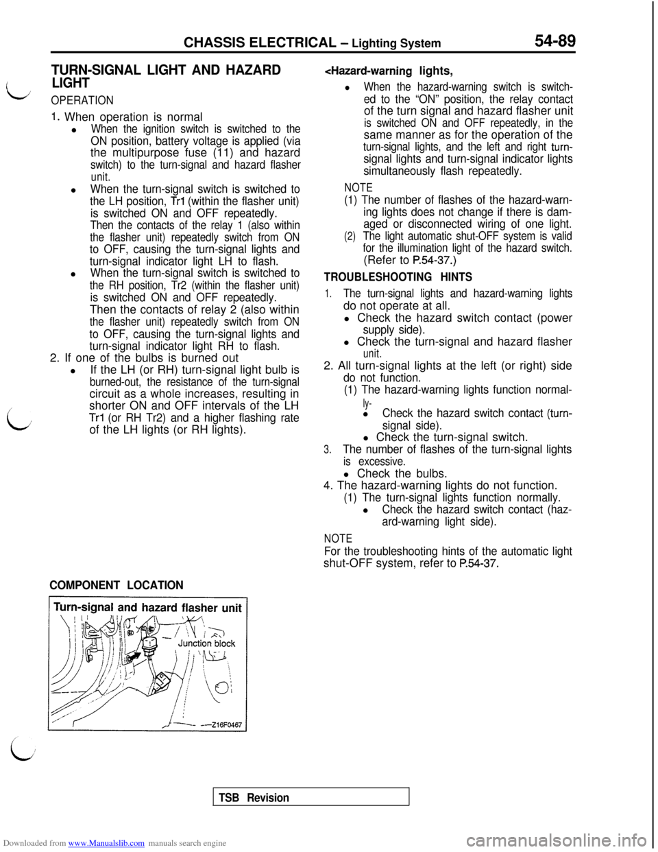
COMPONENT LOCATION
TSB Revision
Page 586 of 738
Downloaded from www.Manualslib.com manuals search engine 54-90CHASSIS ELECTRICAL - Lighting System
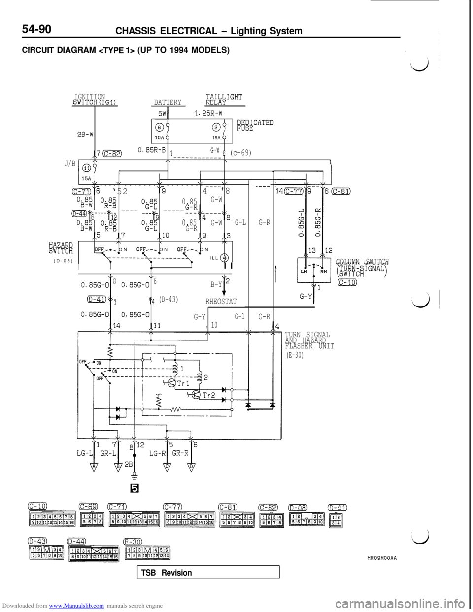
CiRCUlT DIAGRAM
IGNITIONSWITCH(IG1)BATTERY$i[l;\IGHT
1.25R-W
28-W0~&~kCATED15A
,,7 (c-82)0.85R-B lG-w 6 (c-69)----------__J/Blop
,\\1
It115AV\I\/\/\,------------ -------- ----\(c-71,‘% ‘52‘-34 '8
Oi3f$ Ok.8B"O$Z0.85G-W
(D-44)25----2&$ ---- ---'3 -----
op; Ok":"i;";
GIR,z----:'s
0.85G-WG-LG-R,,5,7,,lO,,9,,3
KK%
/\\,\,\OFF-e. ONOFF*-. ONOFF/-. ON
(D-08)ILL
----
G-R
IIII I
*4,
0.85G-080.85G-06B-Y2
(D-41)y3:4 (D-43)I
RHEOSTAT
0.85G-00.85G-0
G-YG-l
,,14,,ll10,
G-RCOLUMN SWITCH
(c-10)
LG-I$GR-$$' LG-i$k$
n
TURN SIGNAL
AND HAZARD
FLASHER UNIT
(E-30)HR09MOOAA
TSB Revision