Ignition MITSUBISHI 3000GT 1994 2.G Manual Online
[x] Cancel search | Manufacturer: MITSUBISHI, Model Year: 1994, Model line: 3000GT, Model: MITSUBISHI 3000GT 1994 2.GPages: 738, PDF Size: 35.06 MB
Page 286 of 738
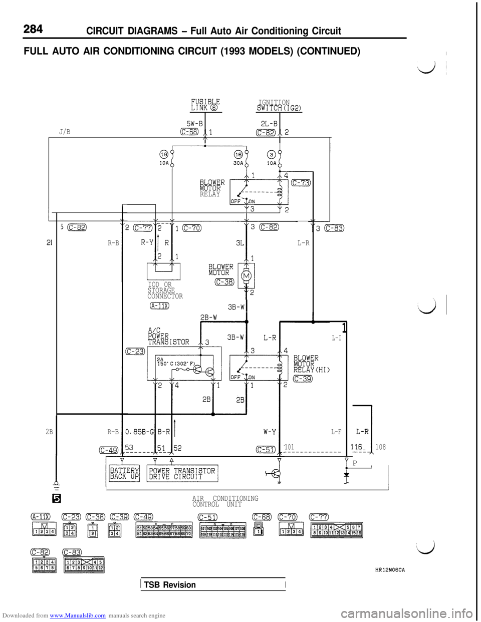
Downloaded from www.Manualslib.com manuals search engine 284CIRCUIT DIAGRAMS - Full Auto Air Conditioning Circuit
FULL AUTO AIR CONDITIONING CIRCUIT (1993 MODELS) (CONTINUED)I
Ij~
KkBsEbIGNITIONSWITCH(IG2)
5W-B2L-BJ/Bm ,,l(c-82),, 2I\
1
21
s(c-82)
R-B
2BR-B
(c-49)
r-
kK%”RELAY
y3y2
v \/.J/
IOD ORSTORAGE
CONNECTORL-R
(A-11X)3B-WI
L-I
L-F
101----_-_--__---
1
1
L-R
3.16108.---P
II
/YII
IaAIR CONDITIONING
CONTROL UNIT
HR12MOGCA
1 TSB RevisionI
Page 290 of 738
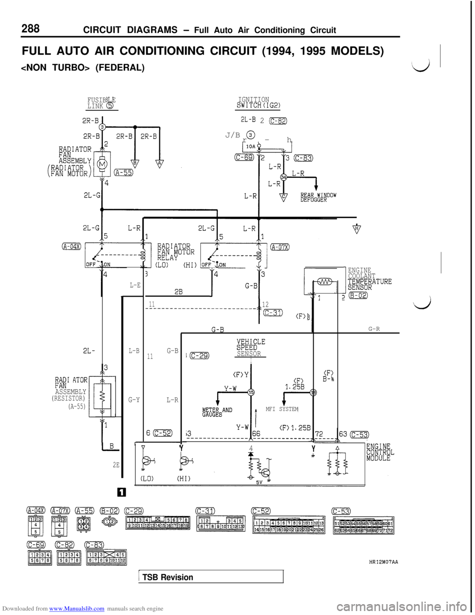
Downloaded from www.Manualslib.com manuals search engine 288CIRCUIT DIAGRAMS - Full Auto Air Conditioning Circuit
FULL AUTO AIR CONDITIONING CIRCUIT (1994, 1995 MODELS)
‘d
IGNITIONSWITCH(IG2)FUSIB E
LINKQ
2L-B 2 mr-h J/B
@
(A-04X)------____
1ENGINE
J
COOLANT;~WFdP;WATURE
20\
d
3 2B T" G-BrL-E
311-------------------________
t
12
(C-31) (F)I
G-R
imSLE
I(c-29)SENSORI
L-BG-B11
G-Y
L-R
S(c-52)
(F)1.25B
TMFI SYSTEM
(F>B-hLa’ AToRASSEMBLY(RESISTOR)
(A-55)
Y4YI
2E
[ TSB Revision
HR12M07AA
Page 293 of 738
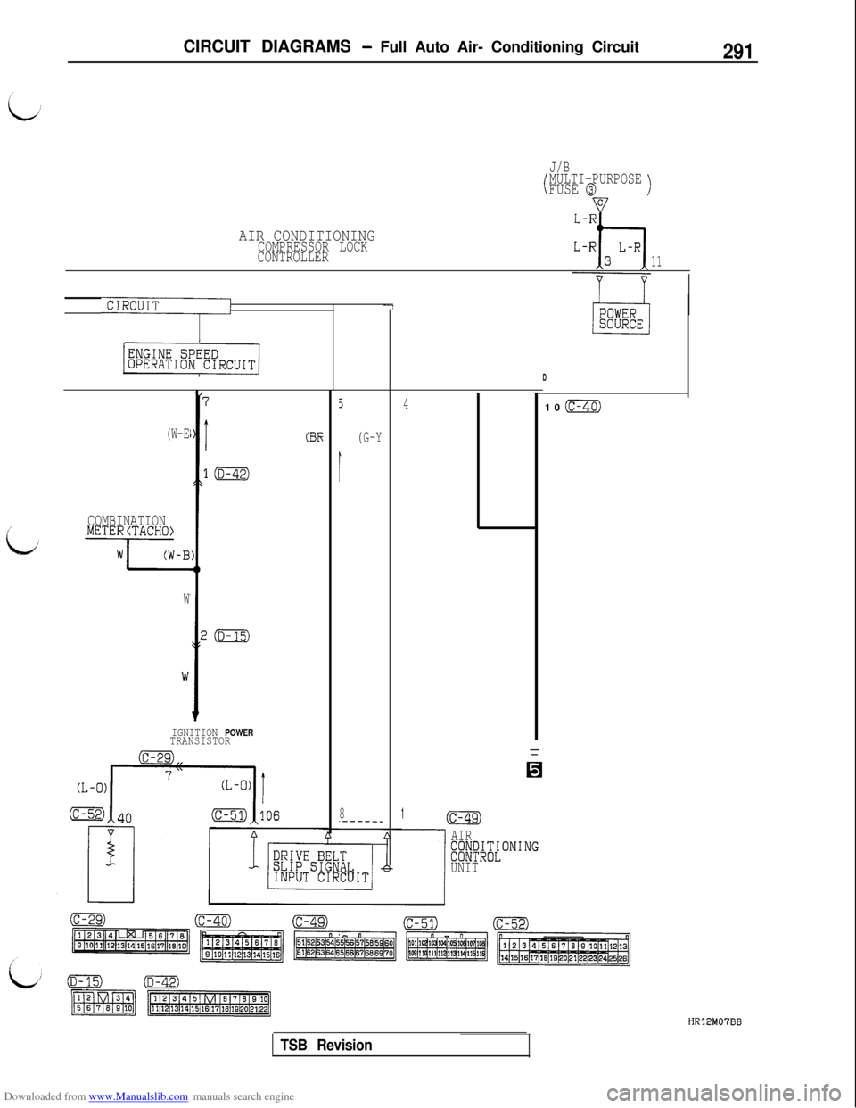
Downloaded from www.Manualslib.com manuals search engine CIRCUIT DIAGRAMS - Full Auto Air- Conditioning Circuit291
J/B
tMULTI-PURPOSEFUSE @)w
AIR CONDITIONINGCOMPRESSOR LOCK
CONTROLLER
11
CIRCUIT/-7
(W-E
COMBINATIONMETERCTACHO)
7-B
W
7
I
l(D-42)
z(D-15)
(BE
IGNITION POWERTRANSISTOR
5
(G-Y
I
8.-----_41(c-49)
D10
(c-40)
AIR~~~I~T~ONING
UNIT
TSB Revision
HR12M07BB
Page 301 of 738
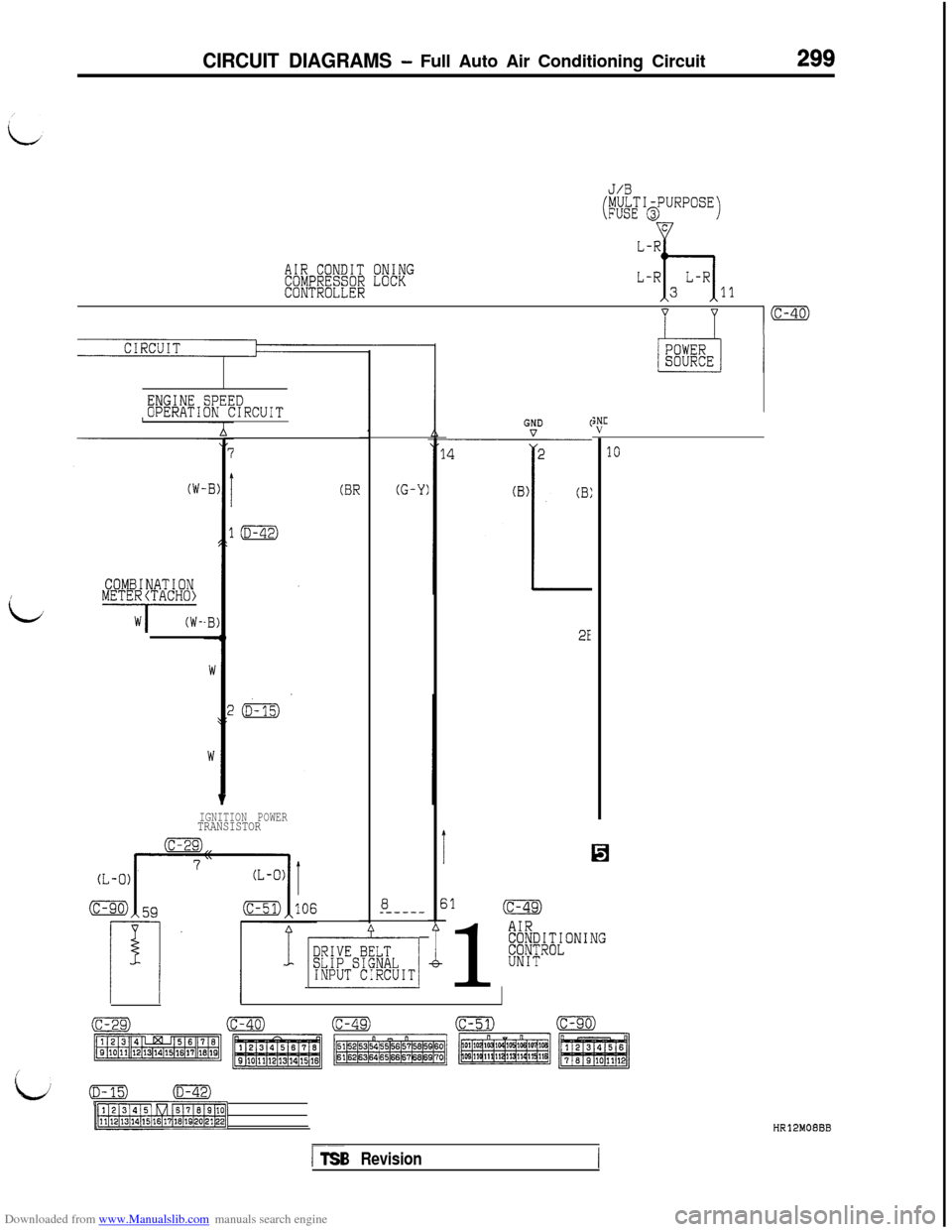
Downloaded from www.Manualslib.com manuals search engine CIRCUIT DIAGRAMS - Full Auto Air Conditioning Circuit299
AIR CONDITCOMPRESSORCONTROLLER
ONINGLOCK
J/B
(MULTI-PURPOSEFUSE @JC
L-R
h
L-RL-R311
ENGINE SPEEDOPERATION CIRCUIT
COMBINATION~METE~/TACH~~-
(BR
IGNITION POWERTRANSISTOR
8_-----
1 p&,-1
(G-Y)
I
E-
;NCV
2E%
;1(c-49)1
AIRE8/~Cl~~ONING
UNIT
10
(c-29)(c-40)(c-49)(c-51)(c-90)
pjz$zmg:,-1
/
kv/(D-15)(D-42)
p?lRq-1HR12MOEBB
r--TSB Revision
Page 306 of 738
Downloaded from www.Manualslib.com manuals search engine 304CIRCUIT DIAGRAMS - Full Auto Air Conditioning Circuit
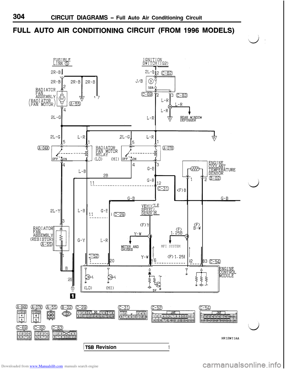
FULL AUTO AIR CONDITIONING CIRCUIT (FROM 1996 MODELS)
i/,
IGNITIONSWITCH(IG2)
r2L-E2R-Bj
J/B @
I--10A
7(c-69)
2L-GIL-R
(A-04X)
I
RADIATOR;;FAyOTOR----------
(LO)(HI) OFF-..%
4G-E
2B
IIG-E
1
(A-07X)----
2E
L-B
(F>l
c111---------__~~----_________
Jr
(F>Y
:LE
!R-I.
RADIATORFANASSEMBL,Y(RESISTOR)
(A-55)
L-BG-E11-----_-_
G-YL-R
(F)B-W(F>1.258
I--
i
MFI SYSTEM
I(F)1.25I6----------___
HR12MllAA
1 TSB Revision1
Page 309 of 738
Downloaded from www.Manualslib.com manuals search engine CIRCUIT DIAGRAMS - Full Auto Air Conditioning Circuit307.
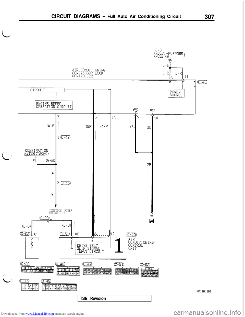
J/B
(MULTI-PURPOSEFUSE @)
v
AIR CONDITIONINGCOMPRESSOR LOCKCONTROLLER11
1
CIRCUITpj-7
(W-E
cvCOMBINATIONMETE~iTACH~~-I”
r
1)
I)-lb
I
;
v
7
I
l(D-42)
!m
IGNITION POWERTRANSISTOR
(BR
5
(G-Y
,
14
(B
GNL:n
(B)
2B1
AIR#/;~;[ONING
UNIT
(c-40)
HR12MllBB
TSB Revision
Page 317 of 738
Downloaded from www.Manualslib.com manuals search engine CIRCUIT DIAGRAMS - Windshield Wiper and Washer Circuit315
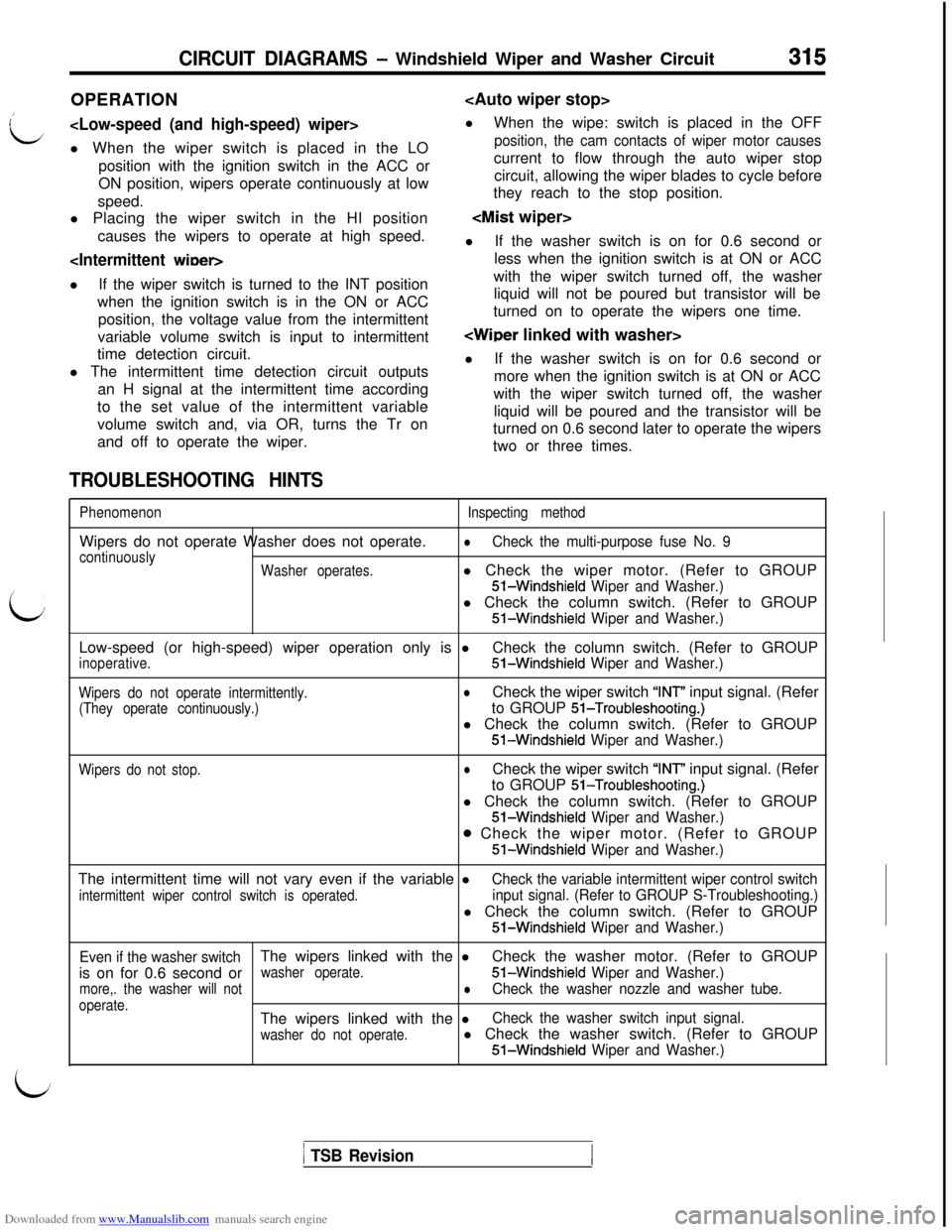
OPERATION
L
l When the wiper switch is placed in the LO
position, the cam contacts of wiper motor causesposition with the ignition switch in the ACC orcurrent to flow through the auto wiper stop
ON position, wipers operate continuously at lowcircuit, allowing the wiper blades to cycle before
speed.they reach to the stop position.
l Placing the wiper switch in the HI position
causes the wipers to operate at high speed.
lIf the washer switch is on for 0.6 second or
less when the ignition switch is at ON or ACC
lIf the wiper switch is turned to the INT positionwith the wiper switch turned off, the washer
when the ignition switch is in the ON or ACCliquid will not be poured but transistor will be
position, the voltage value from the intermittentturned on to operate the wipers one time.
variable volume switch is input to intermittent
’time detection circuit.
l The intermittent time detection circuit outputs
an H signal at the intermittent time according
to the set value of the intermittent variable
volume switch and, via OR, turns the Tr on
and off to operate the wiper.lIf the washer switch is on for 0.6 second or
more when the ignition switch is at ON or ACC
with the wiper switch turned off, the washer
liquid will be poured and the transistor will be
turned on 0.6 second later to operate the wipers
two or three times.
TROUBLESHOOTING HINTS
L
PhenomenonWipers do not operate Washer does not operate.
continuously
Washer operates.Inspecting method
lCheck the multi-purpose fuse No. 9l Check the wiper motor. (Refer to GROUPS-Windshield
Wiper and Washer.)l Check the column switch. (Refer to GROUPS-Windshield
Wiper and Washer.)Low-speed (or high-speed) wiper operation only is l
inoperative.Check the column switch. (Refer to GROUP51-Windshield Wiper and Washer.)
Wipers do not operate intermittently.
(They operate continuously.)lCheck the wiper switch “INT” input signal. (Refer
to GROUP
51-Troubleshooting.)l Check the column switch. (Refer to GROUPS-Windshield
Wiper and Washer.)
Wipers do not stop.lCheck the wiper switch “INT” input signal. (Refer
to GROUP
51-Troubleshooting.)l Check the column switch. (Refer to GROUP
51-Windshield Wiper and Washer.)
o Check the wiper motor. (Refer to GROUP
51-Windshield Wiper and Washer.)The intermittent time will not vary even if the variable l
intermittent wiper control switch is operated.
Check the variable intermittent wiper control switch
input signal. (Refer to GROUP S-Troubleshooting.)l Check the column switch. (Refer to GROUP
51-Windshield Wiper and Washer.)
Even if the washer switchThe wipers linked with the lCheck the washer motor. (Refer to GROUP
is on for 0.6 second or
washer operate.51-Windshield Wiper and Washer.)
more,. the washer will notlCheck the washer nozzle and washer tube.
operate.The wipers linked with the lCheck the washer switch input signal.
washer do not operate.l Check the washer switch. (Refer to GROUP51-Windshield Wiper and Washer.)
1 TSB Revision
Page 318 of 738
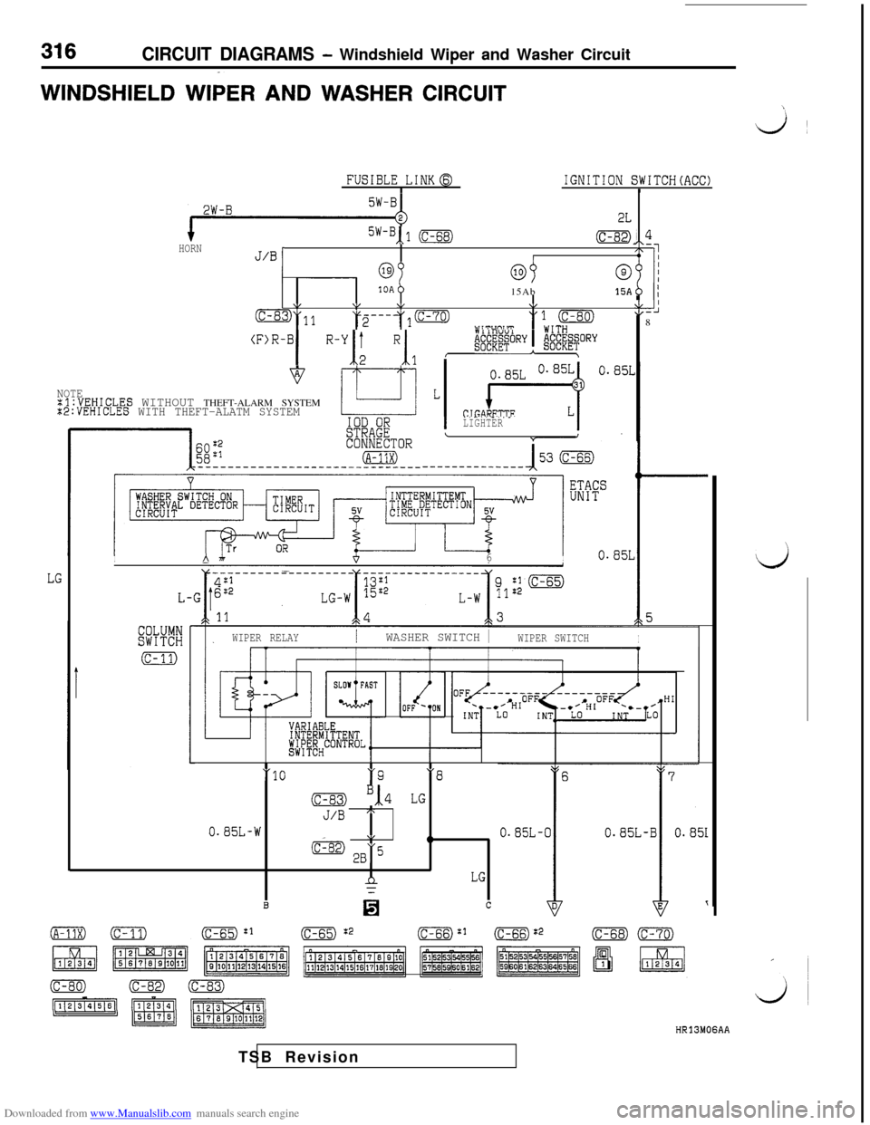
Downloaded from www.Manualslib.com manuals search engine CIRCUIT DIAGRAMS - Windshield Wiper and Washer CircuitWINDSHIELD WIPER
AND WASHER CIRCUIT
\ie/~
FUSIBLE LINKaIIGNITION SWITCH(ACC)I
2W-B
HORN5w-B,,1 (c-68)&, 4
JIBiI2-pI
13Ab15Ab15Ab ;\IV\,\,
O"11=---y(c-701::-J
2w i 'pun, 1T8&.;~~~~ORY
\(F)R-BI "'1; "I, , @@"R'!I
0.85L
NOTE:l:VEHICLES WITHOUT THEFT-ALARM SYSTEMx2:VEHICLES WITH THEFT-ALATM SYSTEM
"GARETTF
I- . -. . . .- . _ -LIGHTER\
LG
_I53 (c-66)---------_____,.I\
IA 7h6I
WIPER RELAYIWASHER SWITCH 1WIPER SWITCHI
-10w9‘8
(c-83) ',,4 LG
J/B A
0.85L-WV
(C-82) *B“50
nLG
B0c
HR13MOGAATSB Revision
d
Page 319 of 738
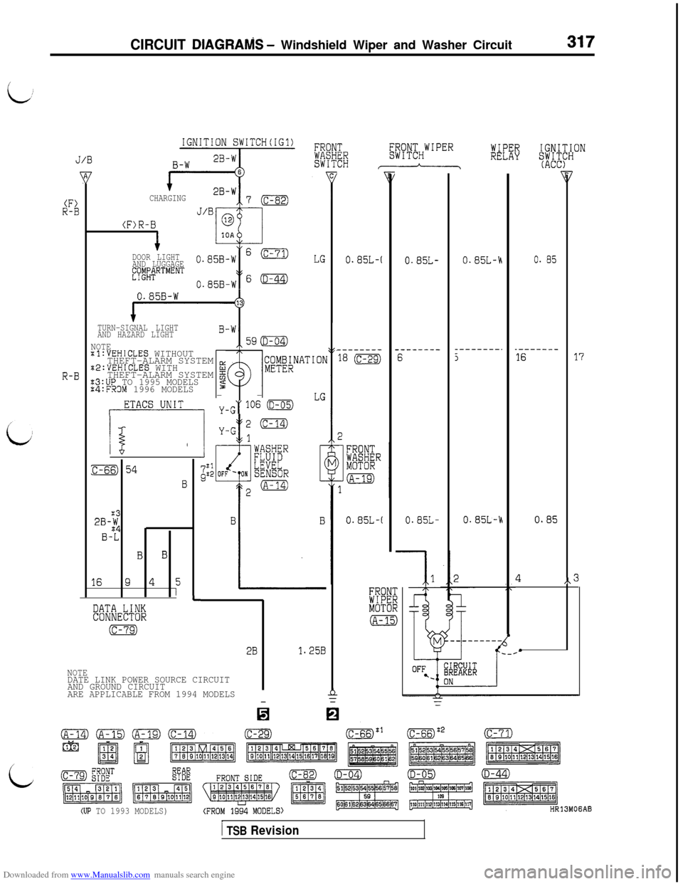
Downloaded from www.Manualslib.com manuals search engine CIRCUIT DIAGRAlViS - Windshield Wiper and Washer Circuit
IGNITION SWITCH(IG1)WIPERIGNITION
J/BRELAYSK?"
+CHARGING
J/B
(F>R-B
I
(F)R-B
DOOR LIGHT
AND LUGGAGE0.858-WS(c-71)LGE~$;;RTMENT
0.858-WFs(D-44)
0.85B-W
0.85L-(0.85L-0.85L-A0. 85
TURN-SIGNAL LIGHT
AND HAZARD LIGHT
NOTEtl:VEHICLES WITHOUTTHEFT-ALARM SYSTEM g
:2:VEHICLES WITHTHEFT-ALARM SYSTEM 2
x3:UP TO 1995 MODELS%4:FROM 1996 MODELS5--
ETACS UNITYmG"106 (D-05)LG
--------
18 (c-29)
--------6
_--_----.5_----___1617
R-B
/!i,
M
2
:c-ss)54
B
0.85L-(0.85L-0.85L-h0.85
43
%3
2B-$
B-L
B B
16945I
A
i%RMOTOR
(A-15)
LDATA LINKCONNECTOR
(c-79)
2B1.25B
NOTEDATE LINK POWER SOURCE CIRCUIT
AND GROUND CIRCUIT
ARE APPLICABLE FROM 1994 MODELS
tzB
(c-79) gygTE%Eo(D-04)(D-05)(D-44)
(UP TO 1993 MODELS))
1 TSB Revision
Page 320 of 738
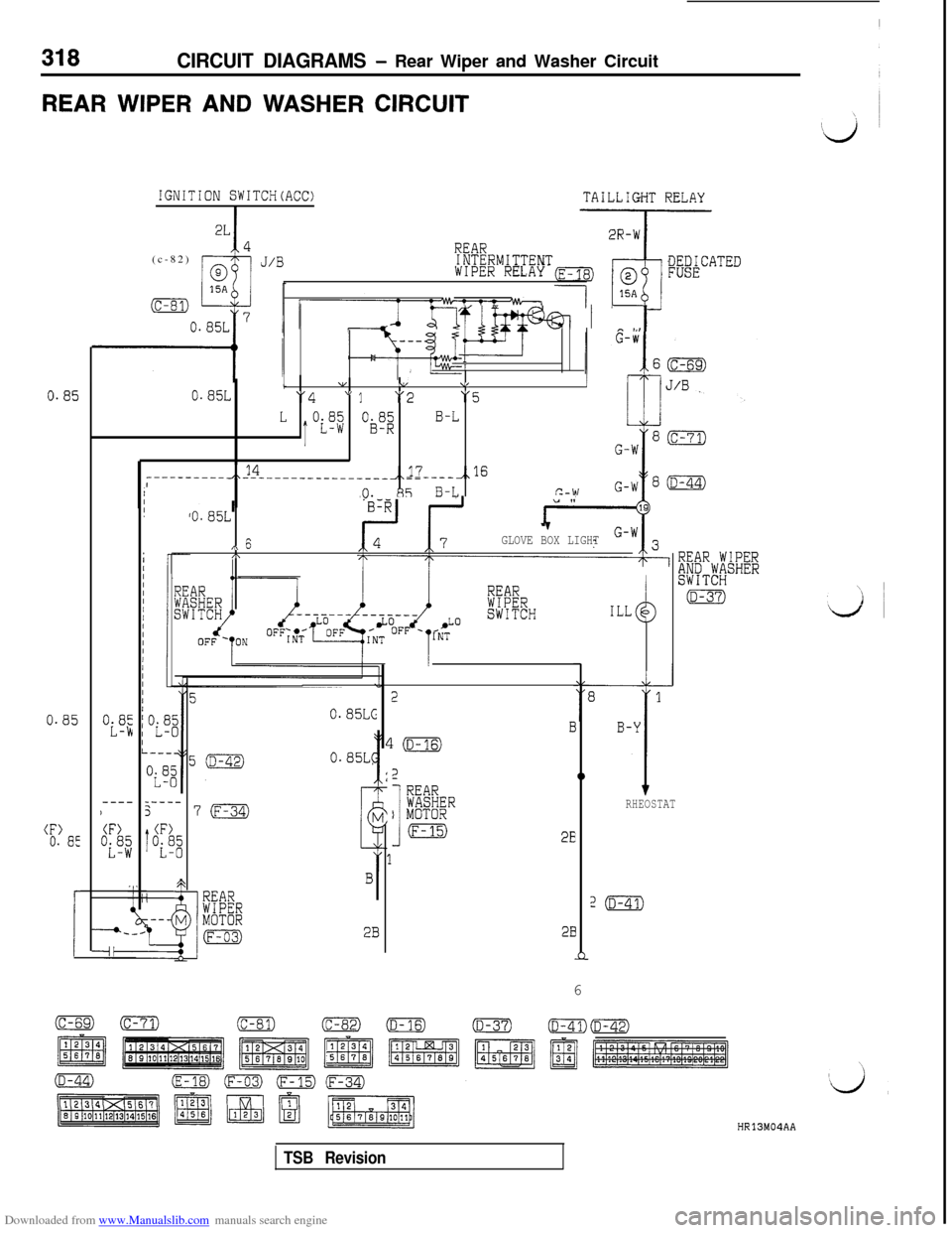
Downloaded from www.Manualslib.com manuals search engine 318CIRCUIT DIAGRAMS - Rear Wiper and Washer Circuit
REAR WIPER AND WASHER CIRCUIT
IGNITION SWITCH(ACC)TAILLIGHT RELAY
I
REAR(c-82)INTERMITTENTWIPER RELAYDEDICATEDFUSE
I.Ji--mm I -1*..I
1 viI1 \/ 1, V0.85Li"4" 1"2"5
L
T
OL3$ OBJ$B-L
----------J,14--------------____,,17 ,,16------,0. 85 B-Lc-w
0.85
0.85
(F>0. a:
0.85L1
,\ 647GLOVE BOX LIGHTI\
REARWIPERSWITCH
REAR WIPER&;PT;/SHER
(D-37)ILLd3
-----57m
1
(F)
"if;
2
2
I
REARWASHERI MOTOR
(F-15)
E1
0
RHEOSTAT
2EI
z(D-41)
28
n6
0.85~~0.85L-b
----,
(F)
"ifi
0.85~~
2B
HR13M04AA
TSB Revision