High idle MITSUBISHI 3000GT 1994 2.G Workshop Manual
[x] Cancel search | Manufacturer: MITSUBISHI, Model Year: 1994, Model line: 3000GT, Model: MITSUBISHI 3000GT 1994 2.GPages: 738, PDF Size: 35.06 MB
Page 453 of 738
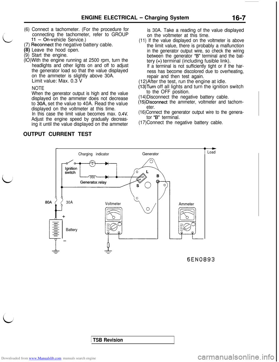
Downloaded from www.Manualslib.com manuals search engine ENGINE ELECTRICAL - Charging System16-7/
L
(6) Connect a tachometer. (For the procedure for
connecting the tachometer, refer to GROUP
- On-vehicle Service.)(7)
kkconnect the negative battery cable.
(8) Leave the hood open.
(9) Start the engine.
(lO)With the engine running at 2500 rpm, turn the
headlights and other lights on and off to adjust
the generator load so that the value displayed
on the ammeter is slightly above 30A.Limit value: Max. 0.3 V
NOTE
When the generator output is high and the value
displayed on the ammeter does not decreaseto
30A, set the value to 40A. Read the value
displayed on the voltmeter at this time.
In this case the limit value becomes max. 0.4V.
Adjust the engine speed by gradually decreas-
ing it until the value displayed on the ammeterOUTPUT CURRENT TEST
is 30A. Take a reading of the value displayed
on the voltmeter at this time.
(11) If the value displayed on the voltmeter is above
the limit value, there is probably a malfunction
in the generator output wire, so check the wiring
between the generator
“IS” terminal and the bat-tery
(+) terminal (including fusible link).
If a terminal is not sufficiently tight or if the har-
ness has become discolored due to overheating,
repair and then test again.(12)After the test, run the engine at idle.
(13)Turn off all lights and turn the ignition switch
to the OFF position.
(14)Disconnect the negative battery cable.
(15)Disconnect the ammeter, voltmeter and tachom-
eter.
(16)Connect the generator output wire to the genera-
tor “B” terminal.
(17)Connect the negative battery cable.
Charging indicatorGenerator
30A
Voltmeter
BatteryAmmeter
t
-Load
6EN0893
1 TSB Revision
Page 454 of 738
Downloaded from www.Manualslib.com manuals search engine 16-8ENGINE ELECTRICAL - Charging System
This test determines whether the generator outputs
normal current.(1) Before the test, always be sure to check the
following.l Generator installation
l
Battery (Refer to GROUP 54 - Battery.)
NOTE
The battery to be used should be slightly dis-charged. The load in a fully-charged battery
will be insufficient and the test may not be able
to be carried out correctly.l Generator drive belt tension (Refer to
GROUP 11- On-vehicle Service.)l Fusible link
l Abnormal noise from the generator while
the engine is running(2) Turn the ignition switch to the OFF position.
(3) Disconnect the negative battery cable.
(4) Disconnect the generator output wire from the
generator
“B” terminal and connect a DC testammeter with a range of O-100 A in series
between the “B” terminal and the disconnected
output wire. (Connect the
(+) lead of the amme-ter to the
“B” terminal, and then connect the(-) lead of the ammeter to the disconnected
output wire.)
Caution
Never use clips but tighten bolts and nutsto connect the line.
Otherwise loose
connections (e.g. using clips) will lead to
a serious accident because of high current.
NOTE
A clamp-type ammeter which enables measure-
ments to be taken without disconnecting the
generator output wire is recommended.(5) Connect a voltmeter with a range of 0
- 20
V between the generator “B” terminal and the
ground. (Connect the
(+) lead of the voltmeterto the “B” terminal, and then connect the (-)
lead of the voltmeter to the ground.)
(6) Connect a tachometer. (For the procedure forconnecting the tachometer, refer to GROUP
11 - On-vehicle Service.)
(7) Connect the negative battery cable.
(8) Leave the hood open.(9) Check to be sure that the reading on the
voltmeter is equal to the battery voltage.
NOTE
If the voltage is 0 V, the cause is probably an
open circuit in the wire or fusible link between
the generator “B” terminal and the battery
(+)
terminal.
(1O)After turning the light switch on and turning on
the headlights, start the engine.
(1l)lmmediately after setting the headlights to high
beam and turning the heater blower switch to
the high revolution position, increase the enginespeed to 2,500
r/min and read the maximum
current output value displayed on the ammeter.
Limit value: 70% of nominal current output
NOTEl
For the nominal current output, refer to the
Generator Specifications.l
Because the current from the battery will
soon drop after the engine is started, the
above step should be carried out as quickly
as possible in order to obtain the maximum
current output value.l The current output value will depend on
the electrical load and the temperature of
the generator body.l
If the electrical load is small while testing,the specified level of current may not be
output even though the generator is normal.
In such cases, increase the electrical load
by leaving the headlights turned on for sometime to discharge the battery or by using
the lighting system in another vehicle, and
then test again.l
The specified level of current also may not
be output if the temperature of the generator
body or the ambient temperature is too high.
In such cases, cool the generator and then
test again.
(12)The reading on the ammeter should be above
the limit value. If the reading is below the limit
value and the generator output wire is normal,
remove the generator from the engine and check
the generator.(13)Run the engine at idle speed after the test.
(14)Turn the ignition switch to the OFF position.
(15)Disconnect the negative battery cable.
(16)Disconnect the ammeter, voltmeter and
tachometer.(17)Connect the generator output wire to the
generator “B” terminal.
(18)Connect the negative battery cable.
TSB Revision
Page 484 of 738
Downloaded from www.Manualslib.com manuals search engine 16-38ENGINE ELECTRICAL - Ignition System
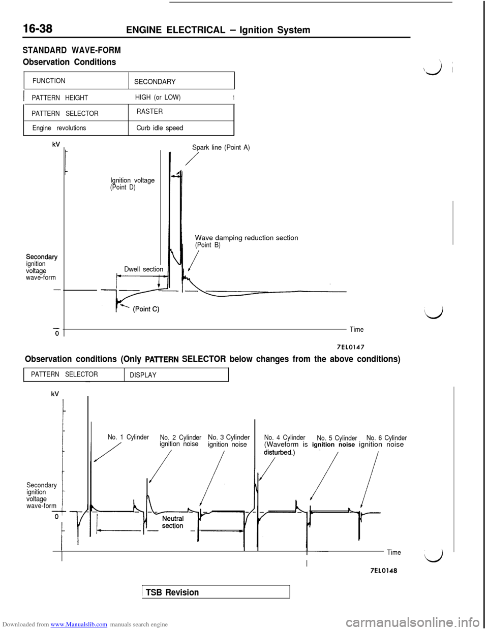
STANDARD WAVE-FORM
Observation Conditions
FUNCTIONSECONDARY
\
\j’i
IPATTERN HEIGHTHIGH (or LOW)1
PATTERN SELECTORRASTER
Engine revolutions
Curb idle speed
kV
Secondary
ignition
voltagewave-form
-6
Ignition voltage(Point D)
Dwell sectionSpark line (Point A)
/Wave damping reduction section
(Point B)
/
Time
7EL0147
Observation conditions (Only PAlTERN SELECTOR below changes from the above conditions)
PATTERN SELECTOR
DISPLAY
Secondary
ignition
voltagewave-formt
No. 1 Cylinder
No. 2 Cylinderignition noiseNo. 3 Cylinder
ignition noiseNo. 4 Cylinder
No. 5 CylinderNo. 6 Cylinder(Waveform is ignition noise ignition noise
TimeI)I7EL0148
1 TSB Revision
Page 487 of 738
Downloaded from www.Manualslib.com manuals search engine ENGINE ELECTRICAL - lanition Svstem16-41
/
L
i
Analyzer
GroundL
01L1008
STANDARD WAVE-FORM
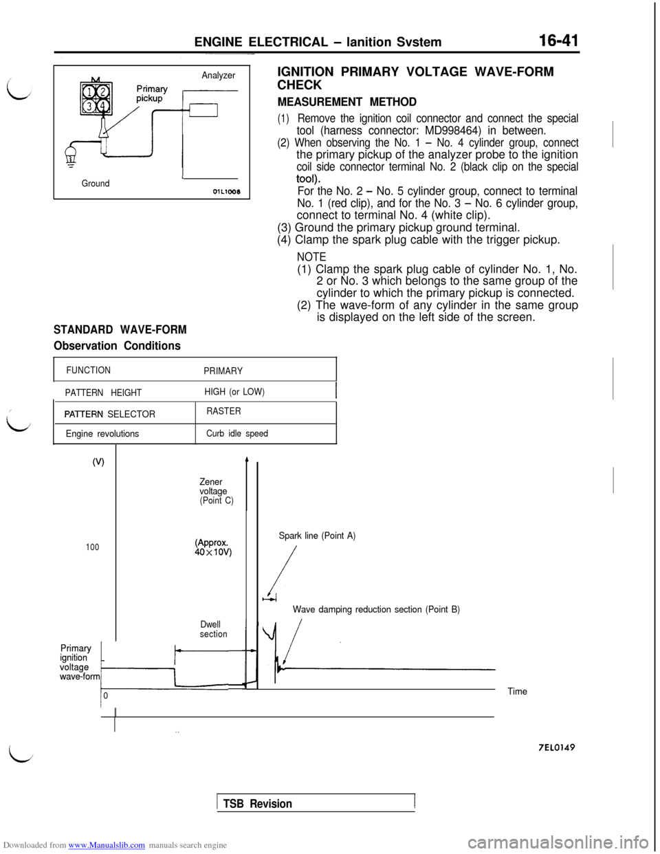
Observation ConditionsIGNITION PRIMARY VOLTAGE WAVE-FORM
CHECK
MEASUREMENT METHOD
(1)Remove the ignition coil connector and connect the special
tool (harness connector: MD998464) in between.
(2) When observing the No. 1 - No. 4 cylinder group, connectthe primary pickup of the analyzer probe to the ignition
coil side connector terminal No. 2 (black clip on the special
tool).
For the No. 2 - No. 5 cylinder group, connect to terminal
No. 1 (red clip), and for the No. 3
- No. 6 cylinder group,connect to terminal No. 4 (white clip).
(3) Ground the primary pickup ground terminal.
(4) Clamp the spark plug cable with the trigger pickup.
NOTE(1) Clamp the spark plug cable of cylinder No. 1, No.
2 or No. 3 which belongs to the same group of the
cylinder to which the primary pickup is connected.
(2) The wave-form of any cylinder in the same group
is displayed on the left side of the screen.
FUNCTION
PRIMARY
PATTERN HEIGHTHIGH (or LOW)
PAVERN SELECTOR
Engine revolutionsRASTER
Curb idle speed
(V)
100
Primary Primary*ignition ignition
voltage voltage
wave-form
owave-formkr
0
Zener
voltage
(Point C)
Dwell
section
b
Spark line (Point A)
/b-4
Wave damping reduction section (Point B)
/
Time
7EL0149
/ TSB Revision
Page 733 of 738
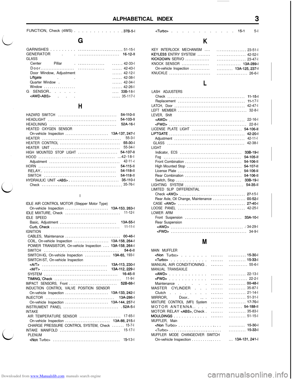
Downloaded from www.Manualslib.com manuals search engine ALPHABETICAL INDEX3FUNCTION, Check (4WS) .
. . . . . . . . . . . .37B-5-l
GARNISHES . . . . . . . . .
GENERATOR . .
GLASSCenter Pillar .
Door.....................
Door Window, Adjustment
Liftgate . .Quarter Window.Window. . . . . . . . . . . . . . . .G SENSOR.. . . . . .
G
.........................51-15-l........................16-12-11
.....................42-33-l.....................42-43-l......42-12-l......42-38-l......42-34-l......42-26-l....338-l 8-l.....35-117-l
H
HAZARD SWITCH..................................54-110-11
HEADLIGHT........................................54-103-11
HEADLINING.......................................52A-16-l
HEATED OXYGEN SENSOROn-vehicle Inspection.........................13A-137,247-l
HEATER..............................................55-3-l
HEATER CONTROL...................................55-30-I
HEATER UNIT........................................55-34-l
HIGH MOUNTED STOP LIGHT.......................54-107-11
HOOD...............................................42-18-lAdjustment.........................................42-11 -I
HORN.............................................54-115-11RELAY..
..........................................54-118-11
SWITCH..........................................54-118-11
HYDRAULIC UNIT CABS>.............................35-110-I
Check
.............................................35-76-lI
IDLE AIR CONTROL MOTOR (Stepper Motor Type)
On-vehicle Inspection.........................13A-153,263-l
IDLE MIXTURE, Check................................11-12-l
IDLE SPEED
Basic, Adjustment.................................13A-55-lCurb,Check........................................11-11-l
IGNITION
CABLES, Maintenance................................00-46-l
COIL, On-vehicle Inspection....................
13A-158,264-l
POWER TRANSISTOR, On-vehicle Inspection....13&158,264-l
SWITCH............................................54-6-11
SWITCH-IG, On-vehicle Inspection...............13A-65, 193-l
SWITCH-ST, On-vehicle Inspection
......................................13A-113,230-l
SYSTEM...........................................16-45-11
TIMING,‘Check.......................................11-9-l
IMPACT SENSORS, Front............................528-68-I
INDUCTION CONTROL VALVE POSITION SENSOROn-vehicle Inspection.........................13A-133,242-l
INJECTOR........................................13A-286-l
On-vehicle Inspection.........................
13A-144,257-l
INSTRUMENT PANEL.................................52A-5-lINTAKE
AIR TEMPERATURE SENSOR........................17-65-l
On-vehicle Inspection..........................13A-88,215-l
CHARGE PRESSURE CONTROL SYSTEM, Check.......15-7-l
INTAKE MANIFOLD...................................15-17-l
PLENUM
K
KEY INTERLOCK MECHANISM....KEYLESS ENTRY SYSTEM........KICKDOWN SERVO...............KNOCK SENSOR.................On-vehicle Inspection............KNUCKLE........................
.................23-51-l.................42-52-l.................23-47-l..............13A-289-l..........
13A-125,237-l..................26-6-l
L
LASH ADJUSTERSCheck.............................................11-15-lReplacement.......................................11-l 7-l
LATCH, Door.........................................42-47-lLEFT MEMBER........................................32-8-l
LEVER, Shift
cFWD>.............................................22-8-lLICENSE PLATE LIGHT.............................54-106-11
LIFTGATE............................................42-20-I
Adjustment.........................................42-11-l
GLASS.............................................42-38-lLIGHT
Indicator, ECS....................................338-19-IFog.............................................54-105-11Front Combination.................................54-106-11High Mounted Stop................................54-107-11License Plate.....................................54-106-11
Rear Combination.................................54-106-11Switch, Stop......................................33B-19-l
LIGHTING SYSTEM..................................54-35-11LIMITED SLIP DIFFERENTIALCheck cAWD>......................................27-l 5-l
Rear Axle, Oil Change, Maintenance...................00-52-I
CASE
LOOSE PANEL.......................................42-25-l
LOWER ARM
Front Suspension.................................33A-10-I
Rear Suspension
M
MAIN MUFFLER
MANUAL AIR CONDITIONING .
MANUAL TRANSAXLE
cFWD> . . . . . . . . . . . .Maintenance. . . . .
MASTER CYLINDER . . .
Clutch . . . . . . . .
MIRROR, Door..
_. .MIXTURE CONTROL (MFI) SystemMOTOR ANTENNA.. . . .
MOTOR RELAY
CABS>, Check .MOULDINGS . . . . . . . . . . . . .MUFFLER, Main
.....................
.......
...............................................................
..........15-30-I..........
15-33-l...........55-6-l..........
22-13-l...........22-2-l..........00-48-I..........35-87-l..........21-14-l..........51-31-l..........17-70-I........54-188-11..........35-83-l..........51-15-l...........
15-30-I..........15-33-l...
13A-131,241-l