Specifications MITSUBISHI 3000GT 1994 2.G Workshop Manual
[x] Cancel search | Manufacturer: MITSUBISHI, Model Year: 1994, Model line: 3000GT, Model: MITSUBISHI 3000GT 1994 2.GPages: 738, PDF Size: 35.06 MB
Page 3 of 738
Downloaded from www.Manualslib.com manuals search engine
i Service Manual
3000~l-
1992-l 996
Volume
2
Electrical
FOREWORD
i
L
This Service Manual has been prepared with the latest service information available at the time of
publication. It is subdivided into various group
categories and each section contains diagnossis,
disassembly, repair, and installation procedures
along with complete specifications and tightening
references. Use of this manual will aid in properly
performing any servicing necessary to maintain or
restore the high levels of performance and reliability
designed into these outstanding vehicles.
@
A
.
.,
WESUF’FORTVOLUNTARY TECHNICIAN
CERTiFiCATlON THROUGH
National lnaltute forAUTOMOTIV ESERVICEEXCELLENC E
Mitsubishi Motors Corporation reserves the right to make changesin design or to make additions to or improvements in its products withou\
timposing any obligations upon itself to install them on its productspreviously manufactured.
L
--
GROUP / SECTION INDEX
General. . . . . . . . . . . . . . . . . . . . . . . .
Fusible Link, Fuse an d IOD or
Storage Connector Locatio n
. . . . . . . . . .w
Inspection Terminal Location . . . . . . . . .
Grounding Location . . . . . . . . . . . . . . . . . .w
m
Relay Location . . . . . . . . . . . . . . . . . . . . . -m
Sensor Locatio
n. . . . . . . . . . . . . -. . . . . . .w
Control Unit Location . . . . . . . . . . . . . . . . .m
Solenoid, Solenoid Valve Location . . . . .d
Diode Location . . . . . . . . . . . . . . -. . . . . . .w
Junction Block . . . . . . . . . . . . . . . . . . . . . . .II
Centralized Junction . . . . . . . . . #. . . . . . .w
Harness Connector Inspectio n. I . . . . . .w
How to Diagnose . . . . . . . . . . . . . -. . . . . . .
111
Configuration Diagrams . . . . . . . . . . . - . .m;
Circuit Diagrams . . . ..*.............
Engine Electrical ...............
ChassisElectrical
............ .
Alphabetical Index .............
NOTE:
For information concerning all compo-
nents other than the electrical system and
on-vehicle service procedures for engines
and transmissions, refer to Volume 1
“Chassis & Body” of this paired Service
Manual.
For overhaul procedures of engines or
transmission, refer to the separately is-
sued Engine Service Manual or Manual/
Automatic Transmission Service Manual.
@ 1995 Mitsubishi Motors CorporationReprinted in USA
Page 447 of 738
Downloaded from www.Manualslib.com manuals search engine 16-1
id
ENGINE
ELECTRICALCONTENTS
i;
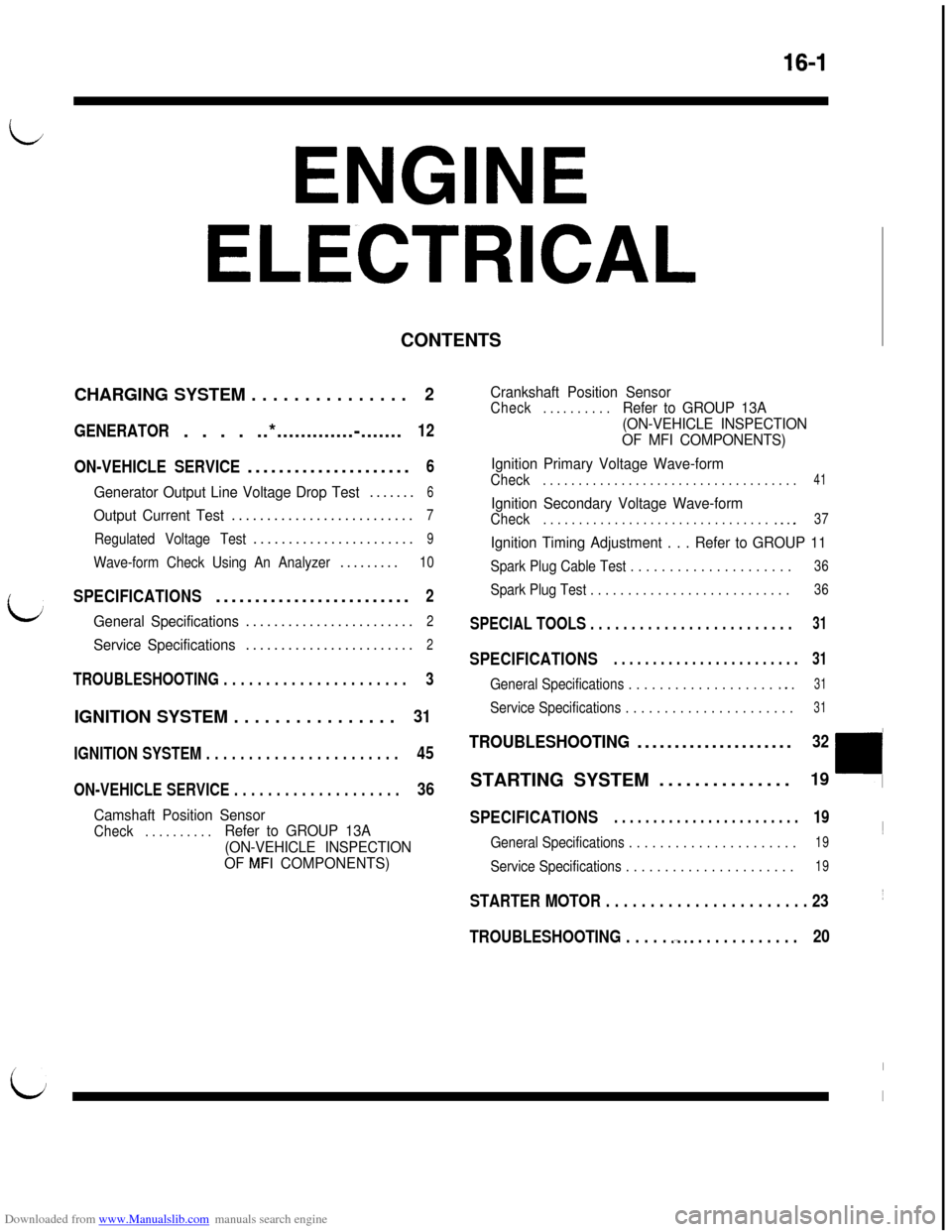
CHARGING SYSTEM . . . . . . . . . . . . . . .2
GENERATOR. . . . ..*.............-.......12
ON-VEHICLE SERVICE.....................
6
Generator Output Line Voltage Drop Test.......6
Output Current Test..........................7
Regulated Voltage Test.......................9
Wave-form Check Using An Analyzer.........10
SPECIFICATIONS.........................2
General Specifications........................2
Service Specifications........................2
TROUBLESHOOTING . . . . . . . . . . . . . . . . . . . . . .3
IGNITION SYSTEM . . . . . . . . . . . . . . . .31
IGNITION SYSTEM . . . . . . . . . . . . . . . . . . . . . . .45
ON-VEHICLE SERVICE . . . . . . . . . . . . . . . . . . . .36
Camshaft Position Sensor
Check. . . . . . . . . .Refer to GROUP 13A
(ON-VEHICLE INSPECTION
OF
MFI COMPONENTS)Crankshaft Position Sensor
Check. . _ . . . . . . .Refer to GROUP 13A
(ON-VEHICLE INSPECTION
OF MFI COMPONENTS)
Ignition Primary Voltage Wave-form
Check. . . . . . . . . . . . . . . . . . . . . . . . . . . . . . . . . . . .41
Ignition Secondary Voltage Wave-form
Check. . . . . . . . . . . . . . . . . . . . . . . . . . . . . . . . .._.37
Ignition Timing Adjustment . . . Refer to GROUP 11
Spark Plug Cable Test . . . . . . . . . . . . . . . . . . . . .36
Spark Plug Test . . . . . . . . . . . . . . . . . . . . . . . . . . .36
SPECIAL TOOLS . . . . . . . . . . . . . . . . . . . . . . . . .31
SPECIFICATIONS. . . . . . . . . . . . . . . . . . . . . . . .31
General Specifications . . . . . . . . . . . . . . . . . . . *. .31
Service Specifications . . . . . . . . . . . . . . . . . . . . . .31
TROUBLESHOOTING.....................32STARTING SYSTEM...............
19
SPECIFICATIONS. . . . . . . . . . . . . . . . . . . . . . . .19~
General Specifications . . . . . . . . . . . . . . . . . . . . . .19
Service Specifications . . . . . . . . . . . . . . . . . . . . . .19
STARTER MOTOR . . . . . . . . . . . . . . . . . . . . . . . 23~
TROUBLESHOOTING . . . . . .-a.. . . . . . . . . . . . .20
L
I
I
Page 448 of 738
Downloaded from www.Manualslib.com manuals search engine ENGINE ELECTRICAL - Charging Svstem
CHARGING SYSTEM
SPECIFICATIONSGENERAL SPECIFICATIONS
GENERATOR
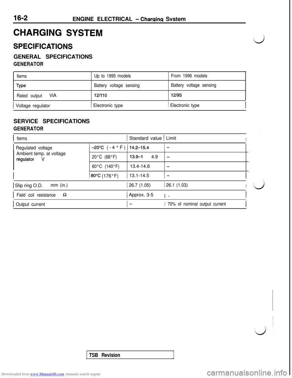
ItemsUp to 1995 modelsFrom 1996 models
TypeBattery voltage sensingBattery voltage sensing
Rated output
VIA12fllO12l95
1 Voltage regulator1 Electronic type1 Electronic typeSERVICE SPECIFICATIONS
GENERATOR
IItems1 Standard value 1 LimitI
I Regulated voltage
Ambient temp. at voltage
rkgulator V
1 -2O’C (-4°F) ( 14.2-15.41 -I
20°C (68°F)13.9-l 4.9 -
60°C (140°F)13.4-14.6 -IIIII
1 80°C (176°F)1 13.1-14.5I-
1 Slip ring O.D.mm (in.)1 26.7 (1.05)/ 26.1 (1.03)I
IField coil resistanceQ1 Approx. 3-5
I-I
I Output currentI-/ 70% of nominal output currentI
TSB Revision
Page 454 of 738
Downloaded from www.Manualslib.com manuals search engine 16-8ENGINE ELECTRICAL - Charging System
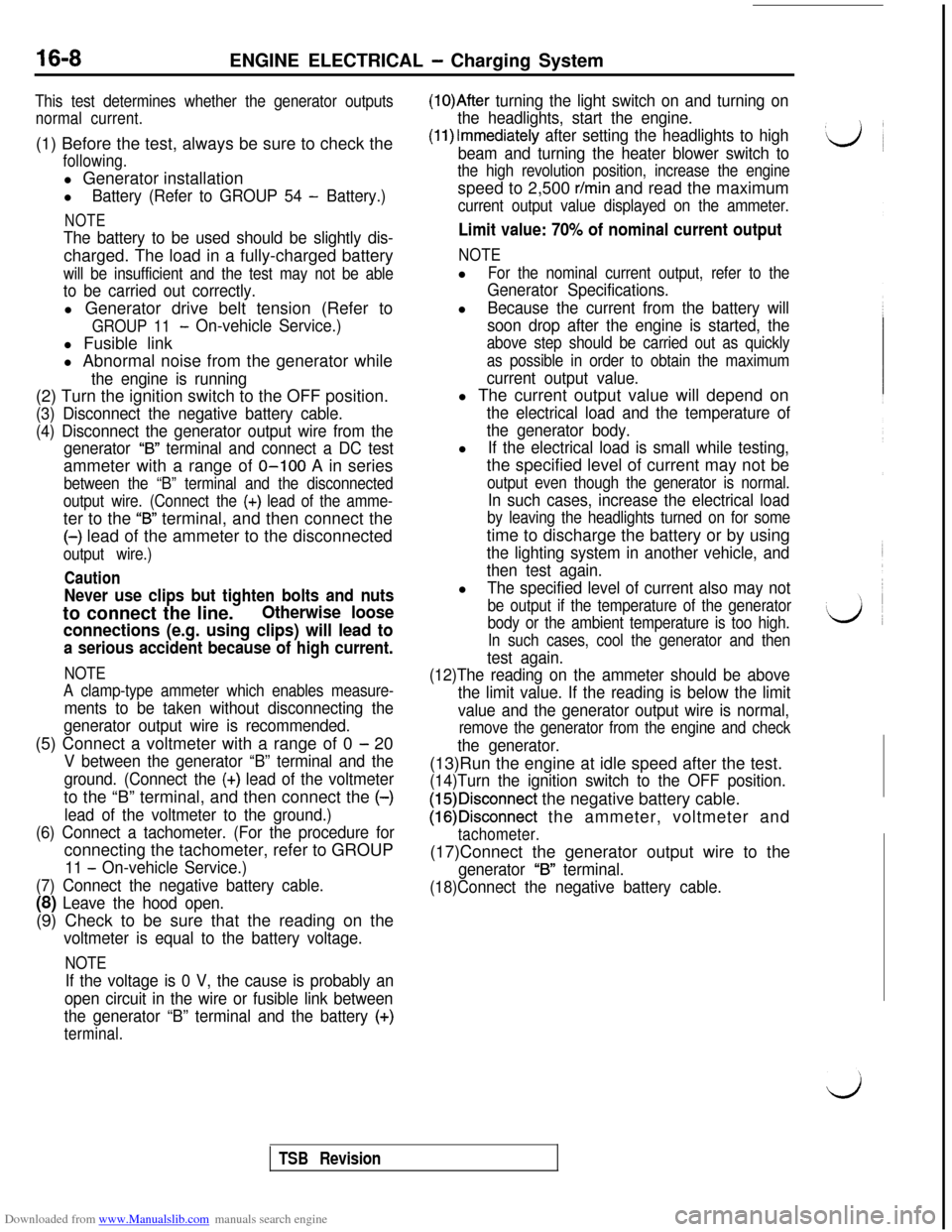
This test determines whether the generator outputs
normal current.(1) Before the test, always be sure to check the
following.l Generator installation
l
Battery (Refer to GROUP 54 - Battery.)
NOTE
The battery to be used should be slightly dis-charged. The load in a fully-charged battery
will be insufficient and the test may not be able
to be carried out correctly.l Generator drive belt tension (Refer to
GROUP 11- On-vehicle Service.)l Fusible link
l Abnormal noise from the generator while
the engine is running(2) Turn the ignition switch to the OFF position.
(3) Disconnect the negative battery cable.
(4) Disconnect the generator output wire from the
generator
“B” terminal and connect a DC testammeter with a range of O-100 A in series
between the “B” terminal and the disconnected
output wire. (Connect the
(+) lead of the amme-ter to the
“B” terminal, and then connect the(-) lead of the ammeter to the disconnected
output wire.)
Caution
Never use clips but tighten bolts and nutsto connect the line.
Otherwise loose
connections (e.g. using clips) will lead to
a serious accident because of high current.
NOTE
A clamp-type ammeter which enables measure-
ments to be taken without disconnecting the
generator output wire is recommended.(5) Connect a voltmeter with a range of 0
- 20
V between the generator “B” terminal and the
ground. (Connect the
(+) lead of the voltmeterto the “B” terminal, and then connect the (-)
lead of the voltmeter to the ground.)
(6) Connect a tachometer. (For the procedure forconnecting the tachometer, refer to GROUP
11 - On-vehicle Service.)
(7) Connect the negative battery cable.
(8) Leave the hood open.(9) Check to be sure that the reading on the
voltmeter is equal to the battery voltage.
NOTE
If the voltage is 0 V, the cause is probably an
open circuit in the wire or fusible link between
the generator “B” terminal and the battery
(+)
terminal.
(1O)After turning the light switch on and turning on
the headlights, start the engine.
(1l)lmmediately after setting the headlights to high
beam and turning the heater blower switch to
the high revolution position, increase the enginespeed to 2,500
r/min and read the maximum
current output value displayed on the ammeter.
Limit value: 70% of nominal current output
NOTEl
For the nominal current output, refer to the
Generator Specifications.l
Because the current from the battery will
soon drop after the engine is started, the
above step should be carried out as quickly
as possible in order to obtain the maximum
current output value.l The current output value will depend on
the electrical load and the temperature of
the generator body.l
If the electrical load is small while testing,the specified level of current may not be
output even though the generator is normal.
In such cases, increase the electrical load
by leaving the headlights turned on for sometime to discharge the battery or by using
the lighting system in another vehicle, and
then test again.l
The specified level of current also may not
be output if the temperature of the generator
body or the ambient temperature is too high.
In such cases, cool the generator and then
test again.
(12)The reading on the ammeter should be above
the limit value. If the reading is below the limit
value and the generator output wire is normal,
remove the generator from the engine and check
the generator.(13)Run the engine at idle speed after the test.
(14)Turn the ignition switch to the OFF position.
(15)Disconnect the negative battery cable.
(16)Disconnect the ammeter, voltmeter and
tachometer.(17)Connect the generator output wire to the
generator “B” terminal.
(18)Connect the negative battery cable.
TSB Revision
Page 465 of 738
Downloaded from www.Manualslib.com manuals search engine ENGINE ELECTRICAL - Starting System16-19
L/J
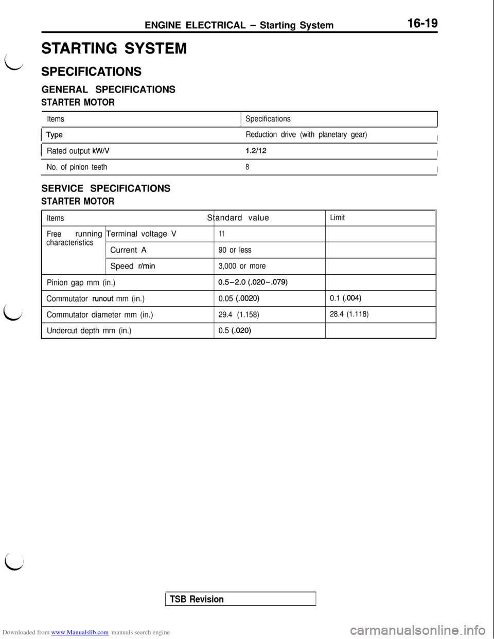
STARTING SYSTEM
SPECIFICATIONSGENERAL SPECIFICATIONS
STARTER MOTOR
ItemsSpecifications
L
ITypeReduction drive (with planetary gear)I
IRated output kW/V1.2112I
No. of pinion teeth8ISERVICE SPECIFICATIONS
STARTER MOTOR
Items
Freerunning Terminal voltage V
characteristicsCurrent A
Speed
r/min
Pinion gap mm (in.)
Commutator
runout mm (in.)
Commutator diameter mm (in.)
Undercut depth mm (in.)Standard value
11
90 or less
3,000 or more
0.5-2.0 (.020-.079)
0.05
(.0020)
29.4 (1.158)
0.5 (.020)Limit
0.1 (.004)
28.4 (1.118)
i
TSB Revision
Page 477 of 738
Downloaded from www.Manualslib.com manuals search engine i/ENGINE ELECTRICAL
- Ignition System
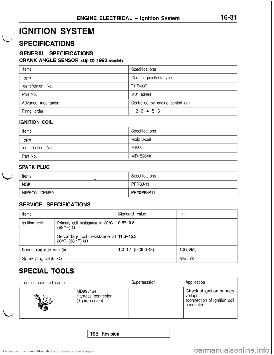
IGNITION SYSTEM
16-31
SPECIFICATIONSGENERAL SPECIFICATIONS
CRANK ANGLE SENSOR cup to 1992 model>
Items
Specifications
TypeContact pointless type
Identification No.
Tl T49371
Part No.MD1 53464
Advance mechanism
Firing orderControlled by engine control unitl-2-3-4-5-6
IGNITION COILrItems
Type
Identification No.SpecificationsMold 3-coil
F-536
L
IPart No.j MD152648I
SPARK PLUG
Items
NGK-Specifications
PFRGJ-11
NIPPON DENS0PK20PRPllSERVICE SPECIFICATIONS
Items
Ignition coilStandard valueLimit
Primary coil resistance at
20°C0.67-0.81(68°F)
RSecondary coil resistance at
11.3-15.3
20°C (68°F) kc2
Spark plug gap mm (in.)1.0-l .l (0.39-0.43)Spark plug cable
kQ
1.3 (.051)
Max. 22SPECIAL
TOOLS
Tool number and nameSupersessionApplication
i
MD998464
Harness connector
(4 pin, square)Check of ignition primaryvoltage
(connection of ignition coil
connector)
i
TSB Revision
Page 497 of 738
Downloaded from www.Manualslib.com manuals search engine 54-1
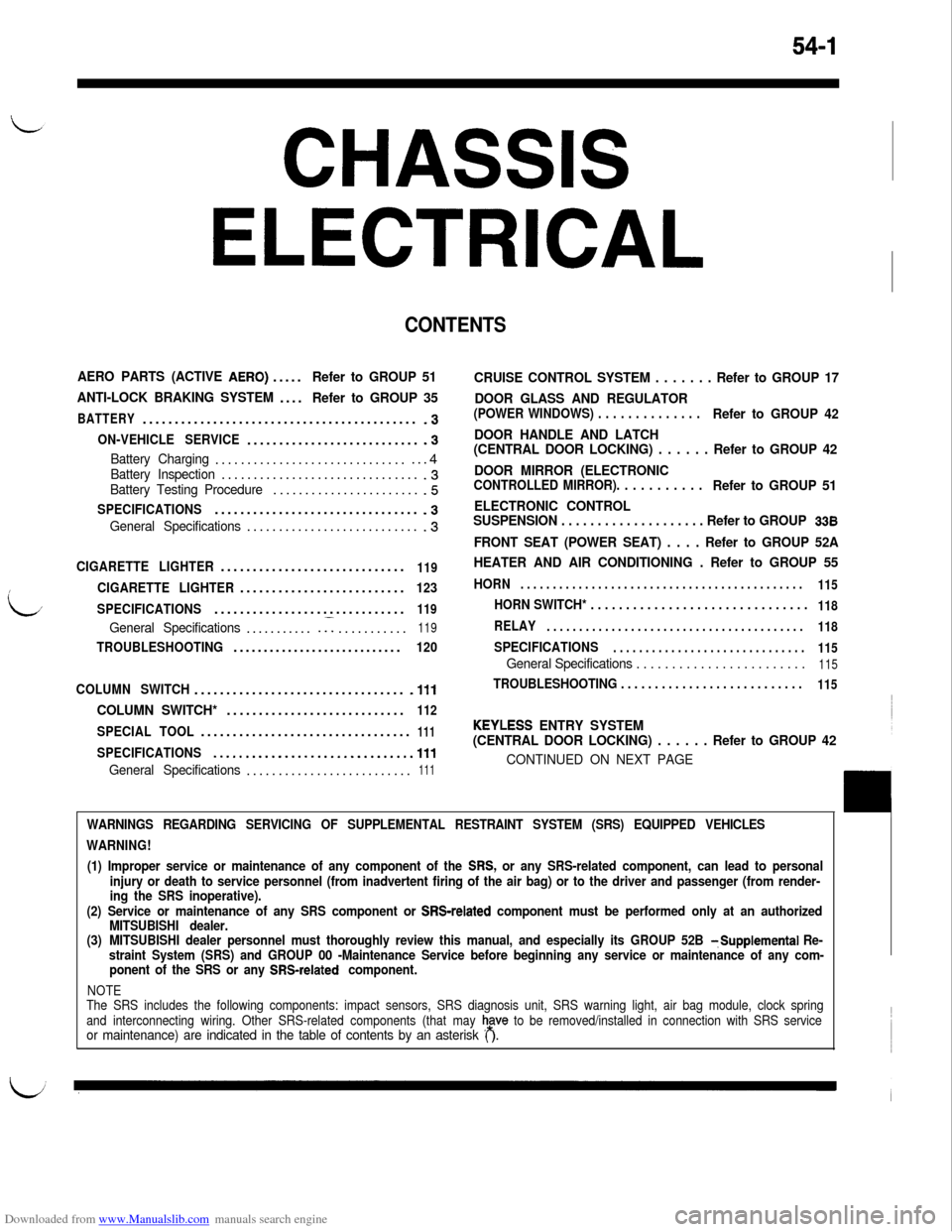
CHASSIS
ELECTRICAL
CONTENTS
AERO PARTS (ACTIVE AERO).....Refer to GROUP 51
ANTI-LOCK BRAKING SYSTEM....
Refer to GROUP 35
BATTERY...........................................-3
ON-VEHICLE SERVICE............................3
Battery Charging.................................4Battery Inspection................................3Battery Testing Procedure........................5
SPECIFICATIONS................................-3
General Specifications............................3
CIGARETTE LIGHTER.............................119
CIGARETTE LIGHTER..........................123
SPECIFICATIONS..............................
119
General Specifications............I...........119
TROUBLESHOOTING............................120
COLUMN SWITCH.................................
.lll
COLUMN SWITCH*............................112
SPECIAL TOOL.................................111
SPECIFICATIONS...............................111
General Specifications..........................111
CRUISE CONTROL SYSTEM . . . . . . . Refer to GROUP 17
DOOR GLASS AND REGULATOR
(POWER WINDOWS) . . . . . . . . . . . . . .Refer to GROUP 42
DOOR HANDLE AND LATCH
(CENTRAL DOOR LOCKING) . . . . . . Refer to GROUP 42
DOOR MIRROR (ELECTRONIC
CONTROLLED MIRROR). . . . . . . . . . .Refer to GROUP 51
ELECTRONIC CONTROL
SUSPENSION . . . . . . . . . . . . . . . . . . . . Refer to GROUP
338
FRONT SEAT (POWER SEAT) . . . . Refer to GROUP 52A
HEATER AND AIR CONDITIONING . Refer to GROUP 55
HORN. . . . . . . . . . . . . . . . . . . . . . . . . . . . . . . . . . . . . . . . . . . .
115
HORN SWITCH* . . . . . . . . . . . . . . . . . . . . . . . . . . . . . . .118
RELAY. . . . . . . . . . . . . . . . . . . . . . . . . . . . . . . . . . . . . . . .
118
SPECIFICATIONS. . . . . . . . . . . . . . . . . . . . . . . . . . . . . .
115
General Specifications . . . . . . . . . . . . . . . . . . . . . . . .115
TROUBLESHOOTING . . . . . . . . . . . . . . . . . . . . . . . . . . .115
KEYLESS ENTRY SYSTEM
(CENTRAL DOOR LOCKING) . . . . . . Refer to GROUP 42
CONTINUED ON NEXT PAGE
WARNINGS REGARDING SERVICING OF SUPPLEMENTAL RESTRAINT SYSTEM (SRS) EQUIPPED VEHICLES
WARNING!
(1) Improper service or maintenance of any component of the
SRS, or any SRS-related component, can lead to personal
injury or death to service personnel (from inadvertent firing of the air bag) or to the driver and passenger (from render-
ing the SRS inoperative).
(2) Service or maintenance of any SRS component or
SRS-related component must be performed only at an authorized
MITSUBISHI dealer.
(3)MITSUBISHI dealer personnel must thoroughly review this manual, and especially its GROUP 52B
TSupplemental Re-
straint System (SRS) and GROUP 00 -Maintenance Service before beginning any service or maintenance of any com-
ponent of the SRS or any
SRS-related component.
NOTE
The SRS includes the following components: impact sensors, SRS diagnosis unit, SRS warning light, air bag module, clock spring
and interconnecting wiring. Other SRS-related components (that may
h,a”” to be removed/installed in connection with SRS serviceor maintenance) are indicated in the table of contents by an asterisk ( ).
Page 498 of 738
Downloaded from www.Manualslib.com manuals search engine 54-2
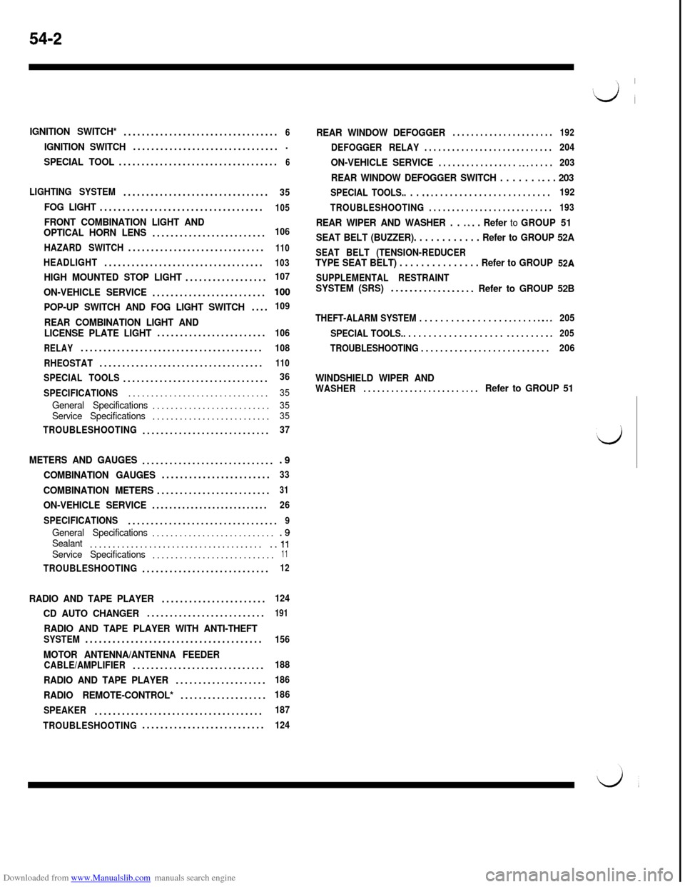
IGNITION SWITCH*..................................6
IGNITION SWITCH.................................
SPECIAL TOOL...................................6
LIGHTING SYSTEM................................35
FOG LIGHT....................................105
FRONT COMBINATION LIGHT AND
OPTICAL HORN LENS.........................106
HAZARD SWITCH..............................
110
HEADLIGHT...................................103
HIGH MOUNTED STOP LIGHT..................107
ON-VEHICLE SERVICE.........................100
POP-UP SWITCH AND FOG LIGHT SWITCH....109
REAR COMBINATION LIGHT AND
LICENSE PLATE LIGHT........................106
RELAY........................................108
RHEOSTAT....................................
110
SPECIAL TOOLS................................36
SPECIFICATIONS...............................
35
General Specifications..........................35Service Specifications..........................35
TROUBLESHOOTING............................37
METERS AND GAUGES..............................9
COMBINATION GAUGES........................33
COMBINATION METERS.........................31
ON-VEHICLE SERVICE...........................26
SPECIFICATIONS.................................
9
General Specifications............................9Sealant........................................ll
Service Specifications...........................11
TROUBLESHOOTING............................12
RADIO AND TAPE PLAYER.......................124
CD AUTO CHANGER..........................191
RADIO AND TAPE PLAYER WITH ANTI-THEFTSYSTEM.......................................156
MOTOR ANTENNA/ANTENNA FEEDERCABLE/AMPLIFIER.............................188
RADIO AND TAPE PLAYER....................186
RADIO REMOTE-CONTROL*...................186
SPEAKER.....................................
187
TROUBLESHOOTING...........................
124
REAR WINDOW DEFOGGER. . . . . . . . . . . . . . . . . . . . . .192
DEFOGGER RELAY. . . . . . . . . . . . . . . . . . . . . . . . . . . .204
ON-VEHICLE SERVICE. . . . . . . . . . . . . . . . . ~ ~. . . . . .203
REAR WINDOW DEFOGGER SWITCH . . . . . . -. . . 203
SPECIAL TOOLS.. . . s.. . . . . . . . . . . . . . . . . . . . . . . . .192
TROUBLESHOOTING
. . . . . . . . . . . . . . . . . . . . . . . . . . .193
REAR WIPER AND WASHER . . ~ *. . Refer to GROUP 51
SEAT BELT (BUZZER). . . . . . . . . . . . Refer to GROUP 52A
SEAT BELT (TENSION-REDUCERTYPE SEAT BELT) . . . . . . . . . . . . . . . Refer to GROUP 52A
SUPPLEMENTAL RESTRAINTSYSTEM (SRS)..-...............Refer to GROUP 52B
THEFT-ALARM SYSTEM . . . . . . . . . . . . . . . . . e . . . . . m.. s205
SPECIAL TOOLS.. . . . . . . . . . . . . . . . . . . .
m . . . . . . . .e205
TROUBLESHOOTING . . . . . . . . . . . . . . . . . . . . . . . . . . .206
WINDSHIELD WIPER ANDWASHER. . . . . . . . . . . . . . . . . . . . . ~. . .Refer to GROUP 51
Page 499 of 738
Downloaded from www.Manualslib.com manuals search engine CHASSIS ELECTRICAL - Battery54-3
BATTERY
LSPECIFICATIONSGENERAL SPECIFICATIONS
ItemsUp to 1993 modelsFrom 1994 models
Type75D26R-MF75D23R-MF
Ampere hours
(5HR) Ah5252
Cranking rating [at -18°C (O’F)] A490520
Reserve capacity min.123118
NOTES
1.CRANKING RATING is the current a battery can deliver for 30 seconds and maintain a terminal voltage of
7.2 volts or greater at a specified temperature.
2.RESERVE CAPACITY RATING is the amount of time a battery can deliver 25A and maintain a minimum terminal
voltage of 10.5 at
27% (80°F).
L
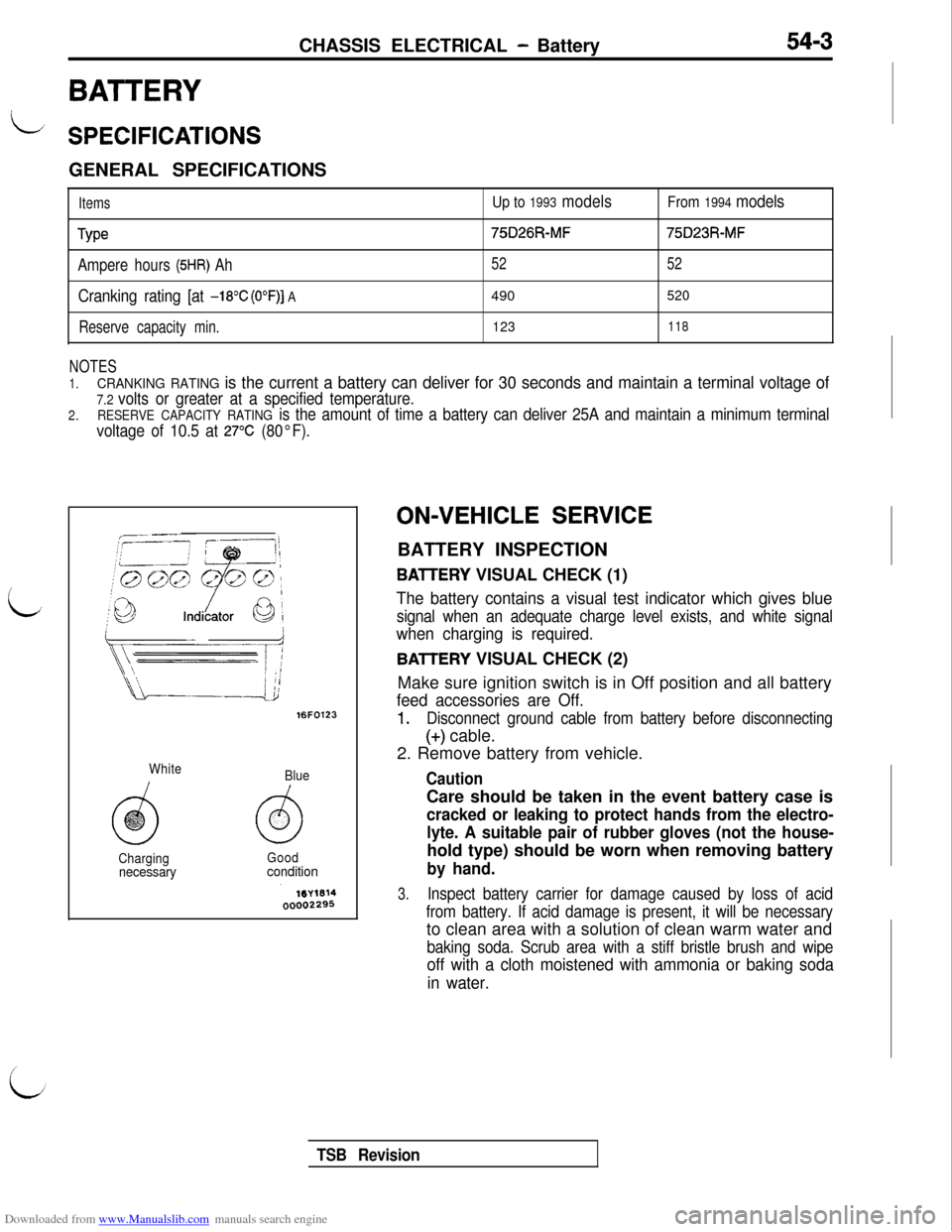
16FO123
White
Blue
ChargingGood
necessaryconditionON-VEHICLE
SERVICE
BATTERY INSPECTION
BAlTERY VISUAL CHECK (1)
The battery contains a visual test indicator which gives blue
signal when an adequate charge level exists, and white signal
when charging is required.
BAlTERY VISUAL CHECK (2)
Make sure ignition switch is in Off position and all battery
feed accessories are Off.
1.Disconnect ground cable from battery before disconnecting
(+) cable.
2. Remove battery from vehicle.
CautionCare should be taken in the event battery case is
cracked or leaking to protect hands from the electro-
lyte. A suitable pair of rubber gloves (not the house-hold type) should be worn when removing battery
by hand.
3.Inspect battery carrier for damage caused by loss of acid
from battery. If acid damage is present, it will be necessaryto clean area with a solution of clean warm water and
baking soda. Scrub area with a stiff bristle brush and wipe
off with a cloth moistened with ammonia or baking soda
in water.
TSB Revision
Page 505 of 738
Downloaded from www.Manualslib.com manuals search engine CHASSIS ELECTRICAL - Meters and Gauaes
(/
METERS AND GAUGES
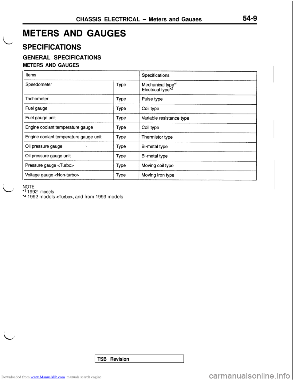
SPECIFICATIONSGENERAL SPECIFICATIONS
METERS AND GAUGES
LNOTE*’ 1992
models
*z 1992 models
TSB Revision