Ecs MITSUBISHI 3000GT 1995 2.G User Guide
[x] Cancel search | Manufacturer: MITSUBISHI, Model Year: 1995, Model line: 3000GT, Model: MITSUBISHI 3000GT 1995 2.GPages: 738, PDF Size: 35.06 MB
Page 61 of 738
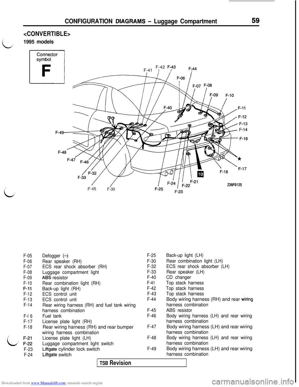
Downloaded from www.Manualslib.com manuals search engine CONFIGURATION DIAGRAMS.- Luggage Compartment
1995 models
59
/
iJ
F-05
F-06
F-07
F-08
F-09
F-10
F-11
F-12
F-13
F-14
F-l 6
F-17
F-18
i: ;:;;
F-23
F-24F-41 I F-42
F;43F;44
Z36FO125F-45
F-30
Defogger (-)
Rear speaker (RH)
ECS rear shock absorber (RH)
Luggage compartment light
ABS resistor
Rear combination light (RH)
Back-up light (RH)
ECS control unit
ECS control unit
Rear wiring harness (RH) and fuel tank wiring
harness combination
Fuel tank
License plate light (RH)Rear wiring harness (RH) and rear bumper
wiring harness combination
License plate light (LH)
Luggage compartment light switch
Liftgate cylinder lock switch
Liftgate switch
F-25
F-30
F-32
F-33
F-40
F-41
F-42
F-43
F-44
F-45
F-46
F-47
F-48
F-49
Back-up light (LH)
Rear combination light (LH)
ECS rear shock absorber (LH)
Rear speaker (LH)
CD changer
Top stack harness
Top stack harness
Top stack harnessBody wiring harness (RH) and rear
wiring
harness combination
ABS resistor
Body wiring harness (LH) and rear wiring
harness combinationBody wiring harness (LH) and rear wiring
harness combination
Body wiring harness (LH) and rear wiring
harness combinationBody wiring harness (LH) and rear wiring
harness combination
TSB Revision
Page 63 of 738
Downloaded from www.Manualslib.com manuals search engine 61
i
CIRCUIT
DlAG.RAMS
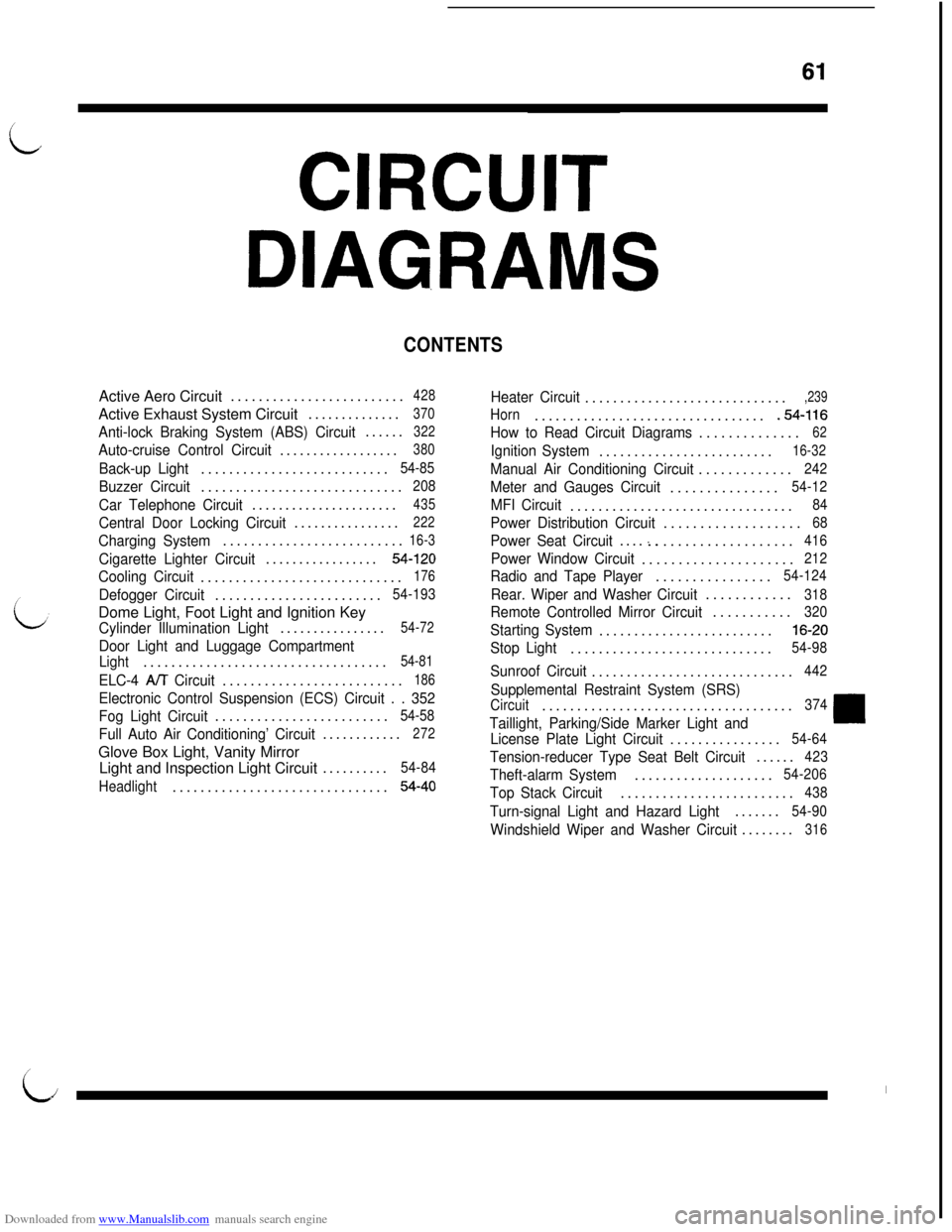
CONTENTSActive Aero Circuit.........................
428Active Exhaust System Circuit..............
370
Anti-lock Braking System (ABS) Circuit......322
Auto-cruise Control Circuit..................380
Back-up Light...........................54-85
Buzzer Circuit.............................208
Car Telephone Circuit......................435
Central Door Locking Circuit................222
Charging System..........................16-3
Cigarette Lighter Circuit.................54-120
Cooling Circuit.............................176
Defogger Circuit........................54-193Dome Light, Foot Light and Ignition Key
Cylinder Illumination Light................54-72
Door Light and Luggage Compartment
Light...................................54-81
ELC-4 A/T Circuit..........................186
Electronic Control Suspension (ECS) Circuit . . 352
Fog Light Circuit.........................
54-58
Full Auto Air Conditioning’ Circuit............272Glove Box Light, Vanity Mirror
Light and Inspection Light Circuit..........
54-84
Headlight...............................
54-40
Heater Circuit.............................,239
Horn..................................54-116
How to Read Circuit Diagrams..............
62
Ignition System.........................16-32
Manual Air Conditioning Circuit.............242
Meter and Gauges Circuit...............54-12
MFI Circuit................................84
Power Distribution Circuit...................68
Power Seat Circuit....:...................416
Power Window Circuit.....................212
Radio and Tape Player................54-124
Rear. Wiper and Washer Circuit............318
Remote Controlled Mirror Circuit...........320
Starting System.........................16-20
Stop Light.............................54-98
Sunroof Circuit.............................442
Supplemental Restraint System (SRS)
Circuit....................................374
Taillight, Parking/Side Marker Light and
License Plate Light Circuit................54-64
Tension-reducer Type Seat Belt Circuit......423
Theft-alarm System....................54-206
Top Stack Circuit.........................438
Turn-signal Light and Hazard Light.......54-90
Windshield Wiper and Washer Circuit........316
I
LiI
Page 354 of 738
Downloaded from www.Manualslib.com manuals search engine 352CIRCUIT DIAGRAMS - Electronic Control Suspension (ECS) Circuit
I
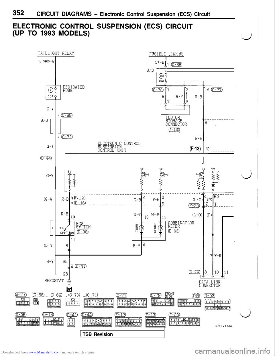
ELECTRONIC CONTROL SUSPENSION (ECS) CIRCUIT
(UP TO 1993 MODELS)
d
1.25R-\i
J/B
F
G-k
(D-44)
G-W
(G-W:
L
(
(B-Y:
B-k
F'%IBLE LINK@I
5w-B,,1 (c-68)
J/B [ i‘
DEDICATEDFUSE
ELECTRONIC CONTROLSUSPENSIONCONTROL UNIT(F-13)
L_____----____________________ ------- ----------------
R-B ‘(F-12)
p(D-16)G-B'W-B 3(L-C1---------------------------- ------,,6(F-20)
R-B, 10W-O 1o W-B 11(L-0
\A COMBINATION5METERe(D-03)
,11
BB-Y 20
i
5v
P) E
4
_
P)
!
PV-l
10--RHEOSTAT $DATA LINK
la
CONNECTOR
(A-13x) (c-68) FE3 (c-70) (c-71)HRlSMllAA
1 TSB Revision
Page 355 of 738
Downloaded from www.Manualslib.com manuals search engine CIRCUIT DIAGRAMS - Electronic Control -Suspension (ECS) Circuit353
IGNI'ISWITC
2L-B
INIG2)
BR-R
010A
THROTTLEgEiW;;ON
(B-05)L-R
I
BR-R 2
50
0.85GL-RVV
II
III/I/IIII/ITJ6
/
L
Y ---------- ----_----------------------_---.i41 G-E----
G-EI
------.55
3G-L
G-L3
53Y-W
45G-BR--------______-__-_-- ----------____---------------------------
51 57B G-I9 ,11_------------ -----_________
G-R00 G-R
Y-W(c-14) 6
t
y-
Y-W
Y
I
COMBINATIONMETERCREED)
SPEEDG SENSORSTEERING
SENSOR(E-28))j& ;E"f& (c-60)
(B-05)0(c-29)(c-53)cc-so) (c-61) FE (c-83)
/HRlSMllAB
TSB Revision
Page 356 of 738
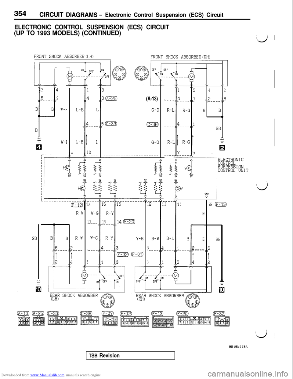
Downloaded from www.Manualslib.com manuals search engine 354CIRCUIT DlAGRAMS - Electronic Control Suspension (ECS) Circuit
ELECTRONIC CONTROL SUSPENSION (ECS) CIRCUIT
(UP TO 1993 MODELS) (CONTINUED)i‘;v’ ’
FRONT SHOCK ABSORBERCLH)FRONT SHOCK ABSORBERCRH)
I I
II
1
1
3
2
6
---_
B
i-
I
B
?
2
W-F
W-I
/----
1
fl.----
I
I.---_
I.
10----
(A-13)
G-O
,----
R-L
(c-36)---_
G-OR-L
--------------------------
----_12
ti5”5”
%-__--_.1
I
3
B-W
3.----
j
B-L
4----
1
\/V
42
,,2,,6/-----\I
BB
0
2B
L-E
L-E
~LICIC~~NIC
SUSPENSIONCONTROL UNIT
-----14
W-G
13----
W-G
'---_
r---
%9”5”
%- -.15
l
14
I
3
F
3
;YNo
----16
R-!
15.---_
R-k
1.----
I
I3i2 (F-13)
R-h
R-W
)r----/
3
(
E
i(F-20)
3E
I
2----
t4
2BY-B2E
7 r
IFF\T--->,,I-OFF -
Ly L
l?EMfi SHOCK ABSORBERTED& SHOCK ABSORBERHRlBMllBA
TSB Revision
Page 358 of 738
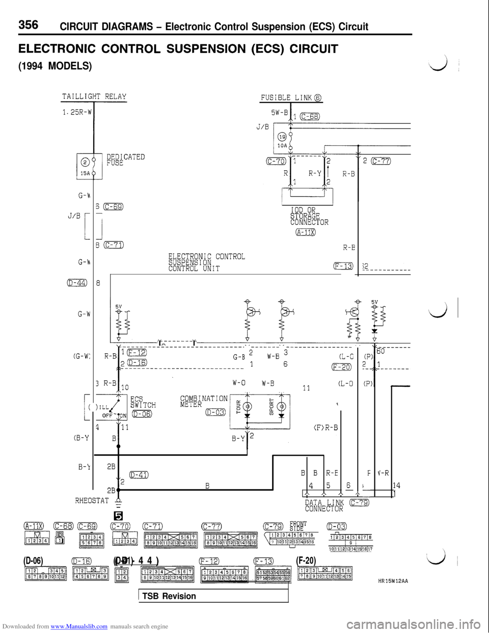
Downloaded from www.Manualslib.com manuals search engine 356CIRCUIT DIAGRAMS - Electronic Control Suspension (ECS) Circuit
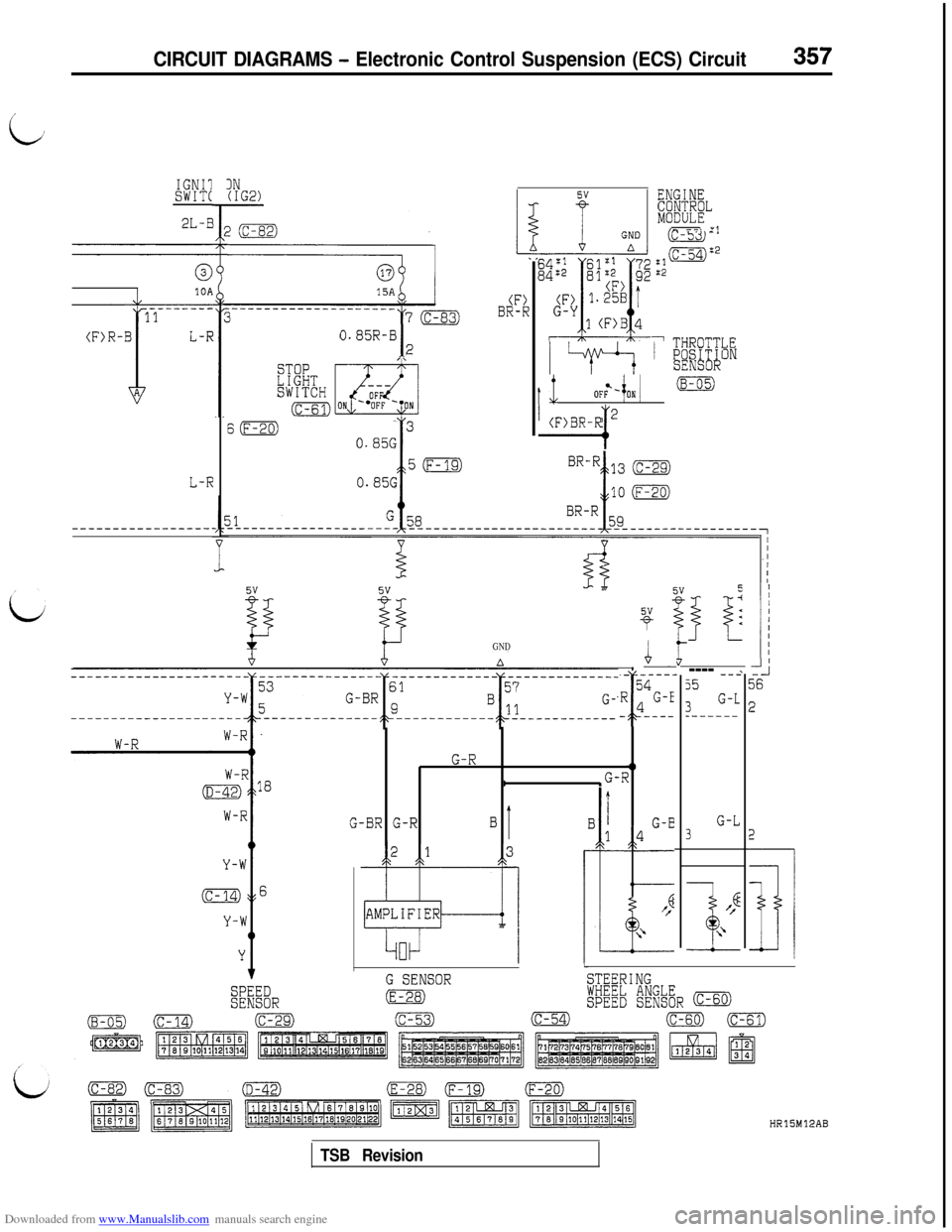
ELECTRONIC CONTROL SUSPENSION (ECS) CIRCUIT
(1994 MODELS)
FUSIBLE [email protected]
G-h
J/BL
G-k
s(c-69)-
1
80
(D-44)8
G-W
(G-W:
3R-B10 l------l 1o W-B 11 (L-0W-O
L
(
(B-Y
B-k
IIIOD ORSTORAGECONNECTOR
(A-11X)
R-B
ELECTRONIC CONTROLSUSPENSIONCONTROL UNIT(F-;2---------
4
-
(P2_-.
(P
F
\-
3
----------------------------- ------- ----------------
R-B ‘(F-12)
p(D-16)G-B 2
I-----------:----------------
W-B 3(L-C1 6(F-20)
I
2B
“2 ma
B B R-E
2BtB4 5A A A
V-R
6-14
1h
RHEOSTATA=DATA LINK (c-7CONNECTOR
(A-11X)(c-70)(D-03)11213/41516/716n
9 ~10~11~12~13j14/15~16112]31415161716
u1 2 110~11/12/13/~4~15)16~17
(D-06)(D-16)
(D-41)(D-44)(F-m(F-20)
HR15M12AA
1 TSB Revision
Page 359 of 738
Downloaded from www.Manualslib.com manuals search engine CIRCUIT DIAGRAMS - Electronic Control Suspension (ECS) Circuit357
c
IGNIlSWIT(
2L-E
IN(IG2)
(F)BR-R
ENGIm
FEE?"__\ *I
/ w I hlKC~i
1 mrli7~TTT,EINSEIUSUK
0.85R-B
I2
60
t 1l OF& 0
I
(F)BR-R 2
0.85G
50
0.85GL-R
5-I<
31
<<
---- --2j5
3G-L_------
11-i36
2
G-L3
Eff
I+
2
jl
GND
- -5
.R L
-%
$_----,4
1G-E----
G-R41
I‘G-R
G-BR G-RBI
L
G SENSORSTEERINGSPEEDSENSOR(E-28)l@b &$& (c-60)
(B-05)0(c-29)(c-53)(c-54)o(c-61)
HRlSM12AB
TSB Revision
Page 360 of 738
Downloaded from www.Manualslib.com manuals search engine I
358CIRCUIT DIAGRAMS - Electronic Control Suspension (ECS) Circuit
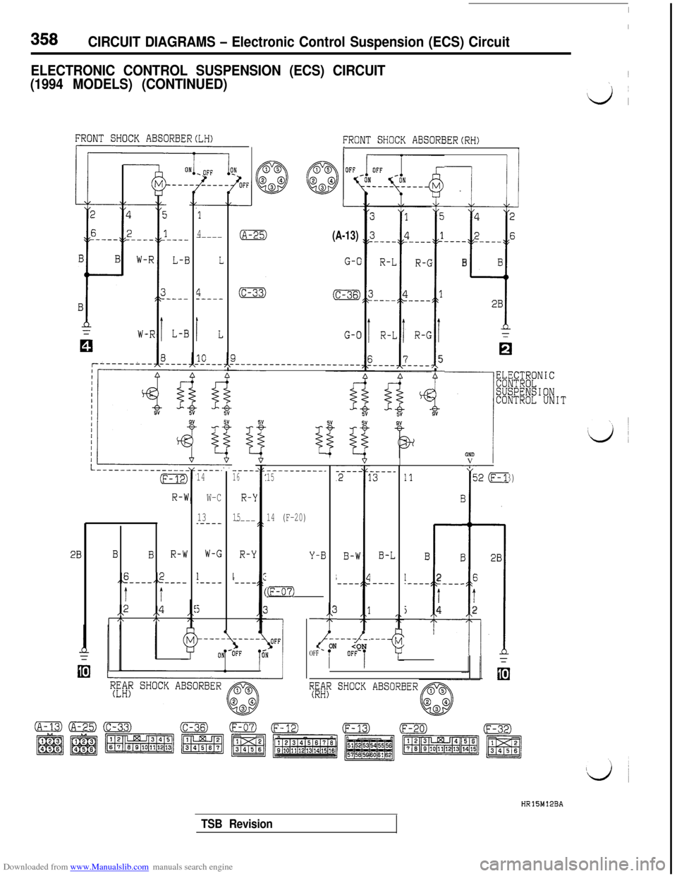
ELECTRONIC CONTROL SUSPENSION (ECS) CIRCUIT
(1994 MODELS) (CONTINUED)1
\
ii,
FRONT SHOCK ABSORBERCLH)
I
!I
FRONT SHOCK ABSORBERCRH)I,I I
7 I!
5
1
!j
1
I
5-
i.9"
42
26
---- ----
il
BB
2B
&W?~NIC
SUSPENSIONCONTROL UNIT
2
6
---
1
B
B
I
‘----
L-B
L-B
(A-13)
G-O
G-O
‘1
4-----
L
4-----
lL
0
p.-___---___________-____
----16
R-\l
15----
R-Y
L---_
EV
-----.14
W-C
13_----
W-G
1.----
5
---------__15
14 (F-20)
Y-BB-L
----
1112 (F-13)EI
3
3
2Ei
TI
rE2
I
BI
1
12
.---- ---_
Ti4
2BBBR-W
,,6,,2---- -___
t t
,,2 ,,4/\I\
:F-32)0
3-
t-._---J_--i
7;;: SHOCK ABSORBER
<_ ONOFF
HR15M12BA
TSB Revision
Page 362 of 738
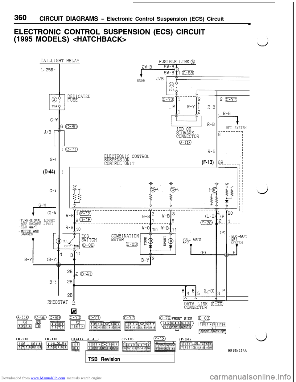
Downloaded from www.Manualslib.com manuals search engine 360CIRCUIT DIAGRAMS - Electronic Control Suspension (ECS) Circuit
ELECTRONIC CONTROL SUSPENSION (ECS) CIRCUIT(1995
MODELS)
TAILLI
1.25R-
G-1
J/B r
1
G-\
(D-44)
G-1
G-W
17
.TURN-SIGNAL LIGHTAND HAZARD LIGHT*ELC-4A/T$&ANDr
I
1
B-Y(B-Y
0-I
r RELAY
mACATED
i(c-69)
I
IOD ORSTORAGECONNECTOR
(A-11x)
;(c-71)R-E
ELECTRONIC CONTROLSUSPENSIONCONTROL UNIT(F-13)
G-B2 w
c t
16---------------------------- ---___(F-20)
W-O 1o W-B 11
2B1h
2B
RHEOSTAT $
H
DATA LINK cCONNECTOR
2(c-77)
R-B
7MFI SYSTEM
(P2_-_
(P:
60
1?-----
: %?-4A’TSYSTEM
1
\(D-06)(D-16)
(D-41)(D-44)
(F-12)
m(F-20)
HR15M13AA
TSB Revision
Page 363 of 738
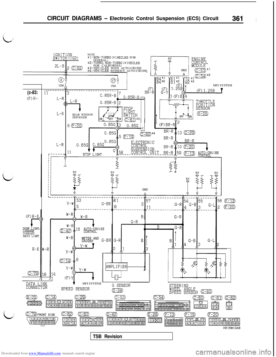
Downloaded from www.Manualslib.com manuals search engine CIRCUIT DIAGRAMS - Electronic Control Suspension (ECS) Circuit361 ~
IGNI'SWIT(
2L-E
ONNOTE(IG2):l:NON-TURBO(VIHECLES FORFEDERAL):2:TURBO,NON-TURBO(VIHECLES
20FOR CALIFORNIA):3:VEHICLES WITH AUTO-CRUISEK4:VEHICLES WITHOUT AUTO-CRUISE
k----MFI SYSTEM
cc1OA.-----___11
L-f;
L-F;
L-R
15A__~_----___-----_____(F)30.85R-B 7 o.~~R-~-BR-k
L-R0
-7
0.85R-B 2
REAR WINDOW
DEFOGGER
(c-83:
(F>R-.
(F)R-E
I-~;~~A~;GH1
COMPART-MENT LIGHI
R-E
THROTTLE;E"$W&&ON
I---------- --------------_53Y-W
I-------------.5G-BI56 (F-13)
20
61
9E
G-RMFI SYSTEM
G SENSORSPEED SENSORm
DATA LINKCONNECTORSTEERING
!FEEb #j&R (c-60)HRlSM13AB
TSB Revision