Data link connector MITSUBISHI 3000GT 1995 2.G Repair Manual
[x] Cancel search | Manufacturer: MITSUBISHI, Model Year: 1995, Model line: 3000GT, Model: MITSUBISHI 3000GT 1995 2.GPages: 738, PDF Size: 35.06 MB
Page 391 of 738
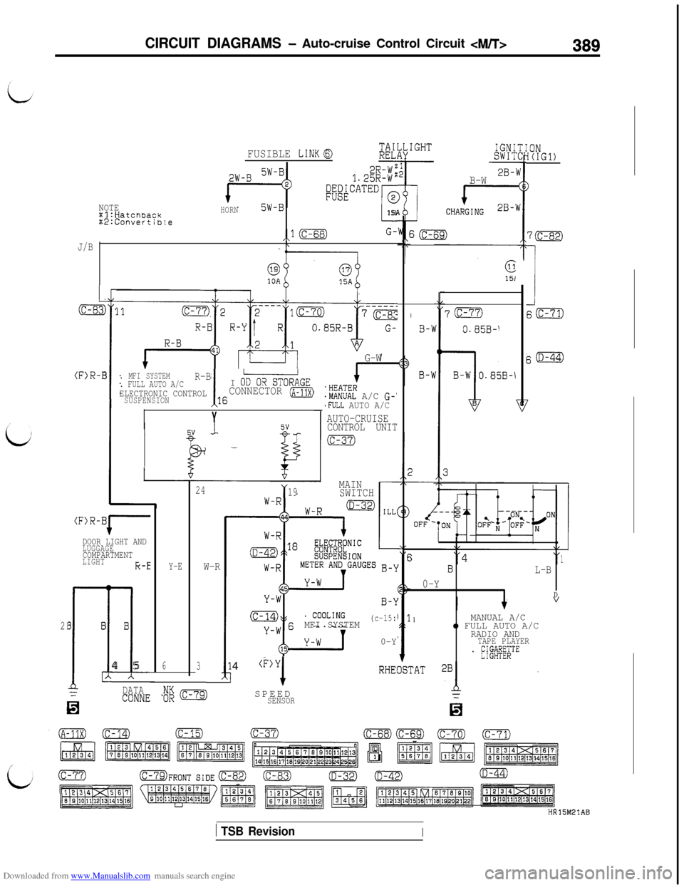
Downloaded from www.Manualslib.com manuals search engine CIRCUIT DIAGRAMS - Auto-cruise Control Circuit 4/T>389
;;L#IGHT:ONI(IG1)
7m
1S(c-71)
E(D-44)
FUSIBLE LINKQ
2B-B-W2R-Wt1.25R-W"#iCATED
ENOTEHORN5W-BXl:Hatchaacki151X2:Convertible
,lBG-
J/B
P
L
(c-83i I
i
3(F)R-I
j1BL-B
0-Y
D
1MANUAL A/Co FULL AUTO A/CRADIO ANDTAPE PLAYER. E;$W$;TEi
B-1
70
0.85B-'
G-W
.HEATER.MANUAL A/C G-''FULL AUTO A/C
. MFI SYSTEMR-B. FULL AUTO A/CI O-STORAGEELECTRONIC CONTROLSUSPENSION!16CONNECTOR (A-11x)
YAUTO-CRUISE
CONTROL UNIT
MAIN
SWITCH
24Y19
Y-EW-R
6
34@)Y
1SPEED
SENSOR
(F)R-BI-*DOOR LIGHT ANDLUGGAGECOMPARTMENTLIGHTk-E
B
IB B
-ll4 5IA A
0
DATACDNNE
MFI SYSTEM(c-15:
0-Y
2
HR15M21AB
1 TSB RevisionI
Page 430 of 738
Downloaded from www.Manualslib.com manuals search engine 428
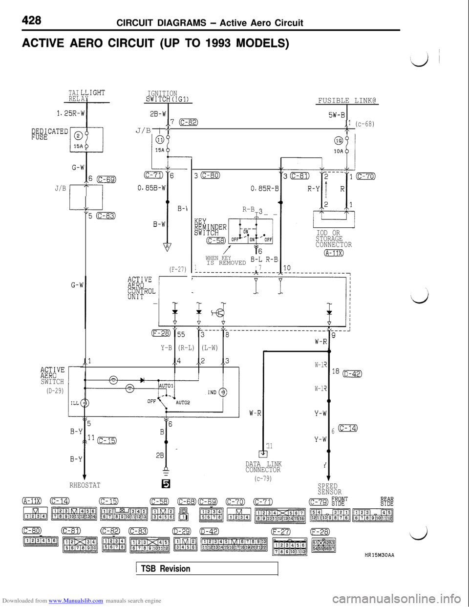
CIRCUIT DIAGRAMS - Active Aero CircuitACTIVE
AERO CIRCUIT (UP TO 1993 MODELS)
TAILL:RELAY
1.25R-
EFATEDr@
p
G-
J/B
c
G-’
%Y”SWITCH
(D-29)
W
I
E
[GHTIGNITIONSWITCH(IG1)FUSIBLE LINK@
2B-W5W-B,,7 (c-82),,I (c-68)J/B 1 AI\
WHEN KEY
1IS REMOVED B-L R-B(F-27)I7---------------A-----
1
30
0.85R-E
R-B SI--
@
10A
-LL\IE
IIOD OR
STORAGE
CONNECTOR
(A-11X)
o”55L3 ----Yi -___------_--_-_______--9
W-lY-B (R-L) (L-W)Ii
,,l,,4,,2,,3
W-l;
W-l
W-l
Y-l
Y-\11
i
0
N
6
v
0
RHEOSTAT[
DATA LINK
CONNECTOR
(c-79)
i
v
SPEED
SENSOR
HR15h430AA
1 TSB Revision
Page 433 of 738
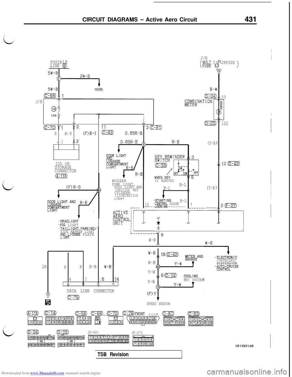
Downloaded from www.Manualslib.com manuals search engine CIRCUIT DIAGRAMS - Active Aero Circuit431
FUSIB E
LINK 6b
J/B
i
@
10A
\,----(c-70)‘1 “2.
RR-Y(F)R-I
,\ 1,.2
IOD ORSTORAGE
CONNECTOR
(F)R-Br
'HEADLIGHT.FOG LIGHT'TAILLIGHTsPARKING,SIDE MARKER LIGHTtjW&ICENSE PLATE
J/B
(WE 'e
BUZZERIS REMOVEDDOME LIGHT.FOOT LIGHT ANDB-L
IGNITION KEYB-LCYLINDER10ILLUMINATIONLIGHT
.STARTINGB-L10jf#Pf~~ DOOR7r--- ----------------------_-
(Y-B
(Y-B
JRPOSE)
59
?jc
I
102
20
-----I/
LL--------19W-R1
.
I.ELECTRONIC
CONTROLNICSUSPENSION
W-R
Y-W
Y-W
MFI SYSTEM
2BBBR-B
451AA*
nDATA LINK CONNECTOR(F>Y
n
(c-79)
SPEED SENSOR
(A-11X)0(c-58) (c-68) 0773 OFRONT SIDE (c-81)(c-83)
(D-42)
(F-27)
HR15M31AB
TSB Revision
Page 435 of 738
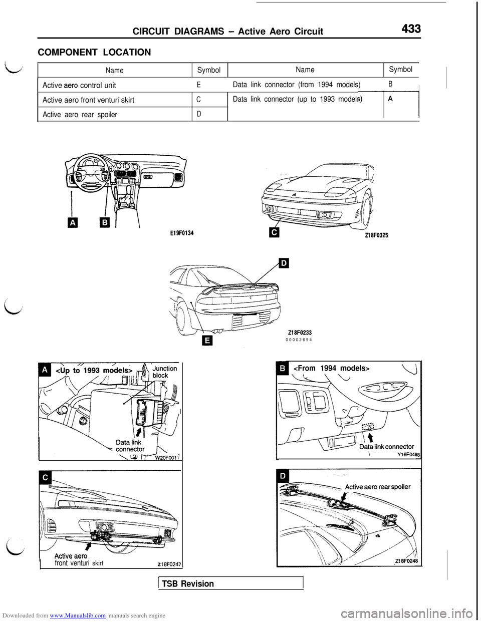
Downloaded from www.Manualslib.com manuals search engine CIRCUIT DIAGRAMS - Active Aero Circuit433COMPONENT LOCATION
L/NameSymbolNameSymbol
IActive aero control unitEData link connector (from 1994 models)BI
i
Active aero front venturi skirt
Active aero rear spoiler
CData link connector (up to 1993 models)
D--r-l
El9F0134
‘\{\ j \ \is/y
front venturi skirt218FO24:
-I
7
218FO23300002694
-\Y16Fo4!
[ TSB Revision
Page 440 of 738
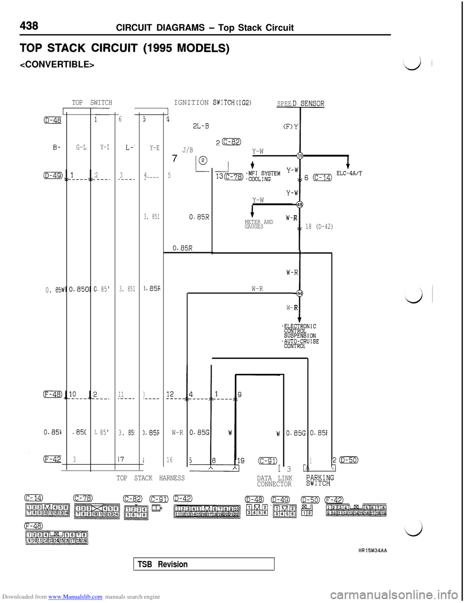
Downloaded from www.Manualslib.com manuals search engine 438CIRCUIT DIAGRAMS - Top Stack Circuit
TOP STACK CIRCUIT (1995 MODELS)
TOP SWITCHIGNITION SWITCH(IG2)SPEE
1!l2L-B(F)7
-
FcFF2y)
J/BY-W
L0
5
DS
Y
15
-W
i
.W45
R
65
G-LY-IL-‘Y-E
2---.3----_4.----
Y-Y-W
3. 8510.85RMETER ANDW-
GAUGES
0.85R
0. 85\1. 85'3. 8511.85-bW-R
11.----3.----
0.851.85(I. 85'3. 853).85FW-R
317i16
16 o ELC-4A/T
18 (D-42)
t
,R
-1
44
R
CTRt:gs
0-dTROI
W-
W-
%sus
‘%I
INIC
iIONWISE
0.85G0.85i3
c
1A
-
r(D-50)
1\
TOP STACK HARNESS
DATA LINK
CONNECTORK%i"
HR15M34AA
TSB Revision
Page 535 of 738
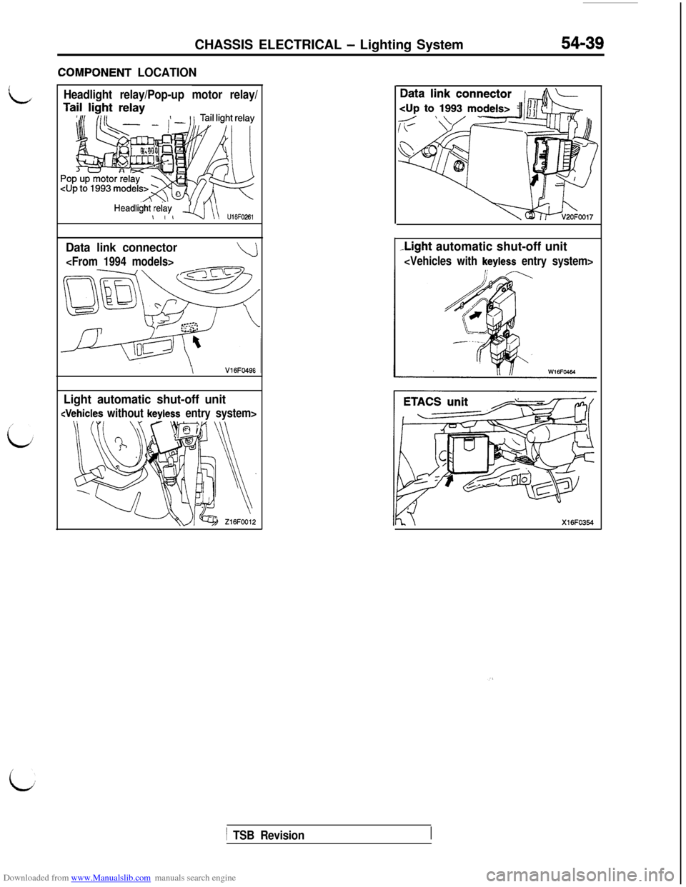
Downloaded from www.Manualslib.com manuals search engine CHASSIS ELECTRICAL - Lighting System54-39
ZOMPONENT LOCATION
Headlight relay/Pop-up motor relay/
HeadliiW,$w, q\\ u,6F026,
Data link connector
\V16FO49E
Light automatic shut-off unit
-Light automatic shut-off unit
i
1 TSB Revision
Page 539 of 738
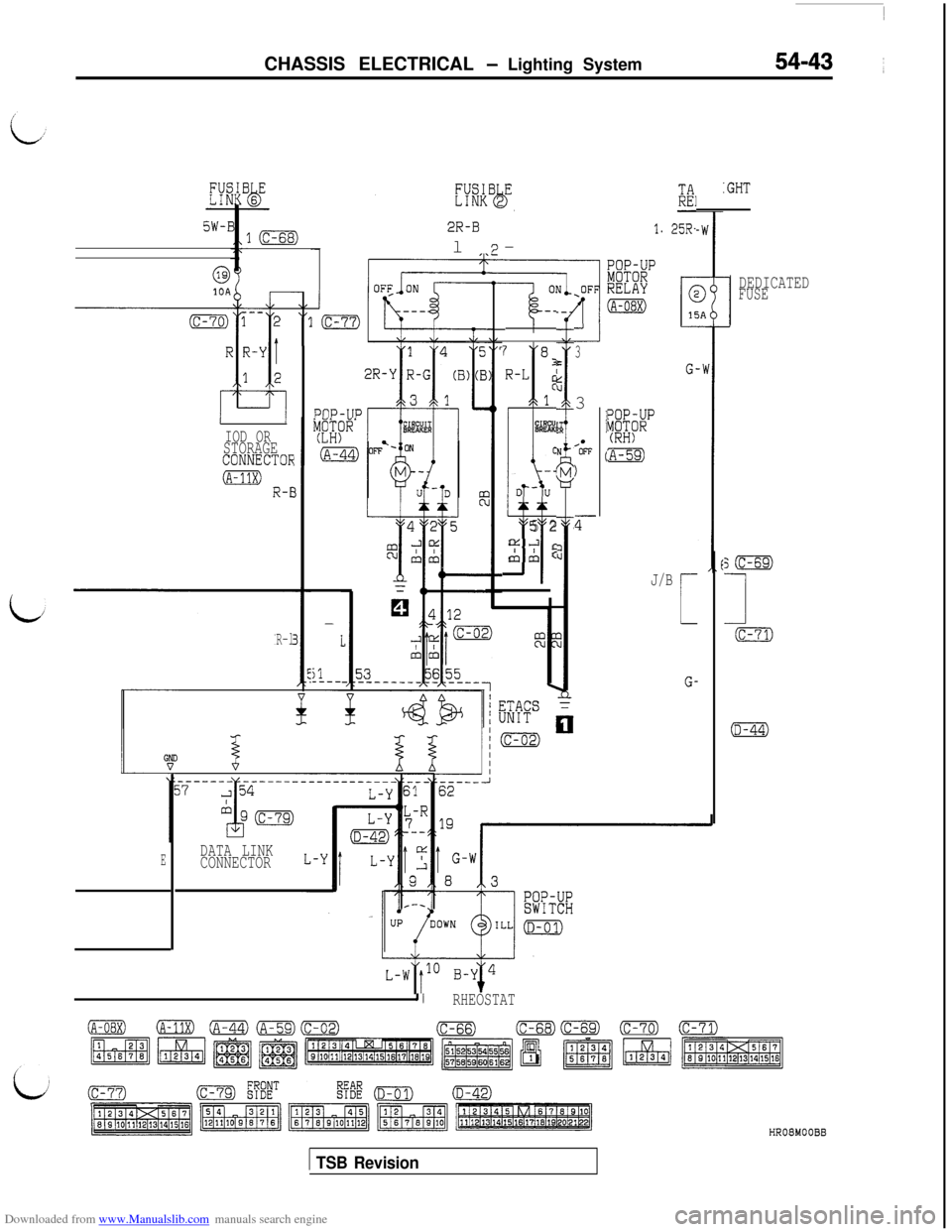
Downloaded from www.Manualslib.com manuals search engine CHASSIS ELECTRICAL - Lighting System54-43 ~
?IIK:GHT
l(c-68)2R-Bl-'I. 25R-
I7
@10ADEDICATEDFUSE-_
-kz-.-l7 8I-L:1
%%!
C
u
-4
D-u
5 2a.3
&A:PllP-TIP
33
/*OFF
)
z--
EYi~p(RH)
:A-59)
J/B
L-
G-
IOD ORSTORAGECONNECTOk
0 R-E
R-l
;m
1
(c-71)
(D-44)
-
I
il_---
DATA LINK
CONNECTORE
I/RHEOSTAT
1 TSB RevisionHR08MOOBB
Page 543 of 738
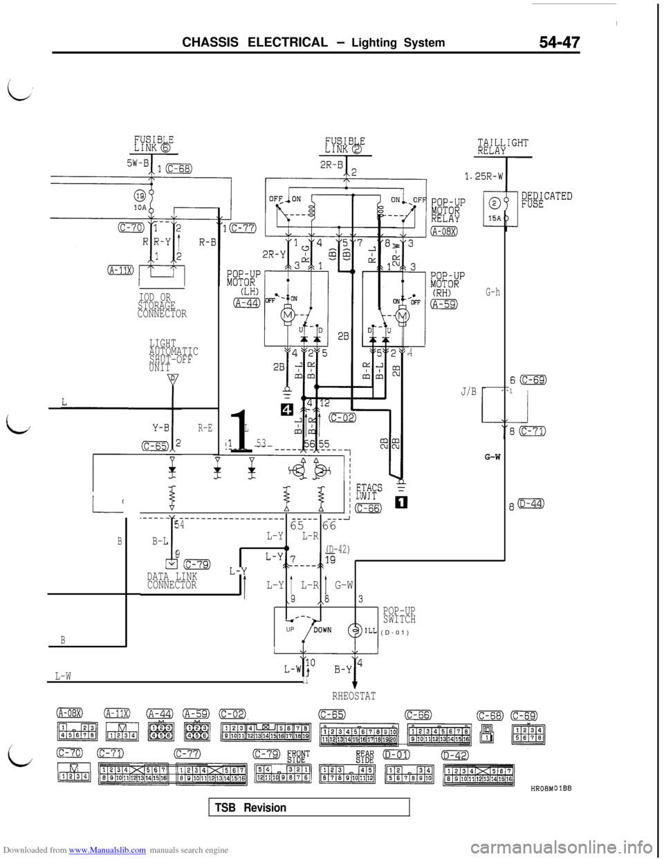
Downloaded from www.Manualslib.com manuals search engine CHASSIS ELECTRICAL - Lighting System54-47
G-hIOD ORSTORAGE
CONNECTOR
LIGHTAUTOMATIC
SHUT-OFF
UNIT
4
J/B
S(c-69)1
1
L
1153.---- ---
/R-E
G-W
%I 1
/ #FS
/m mL-L
B
.----- ____________------_
Ii
----- ---J5465 66
B-LL-YL-R
90(D-42)
Ic-79) L-y L-y:;_7_--+p
DATA LINK
CONNECTOR1L-Y b L-R 1, G-W 3
\/\POP-UPr-.-sSWITCHUPILL (D-01)B
L-WII+RHEOSTAT
/
id
OlBB
TSB Revision
Page 552 of 738
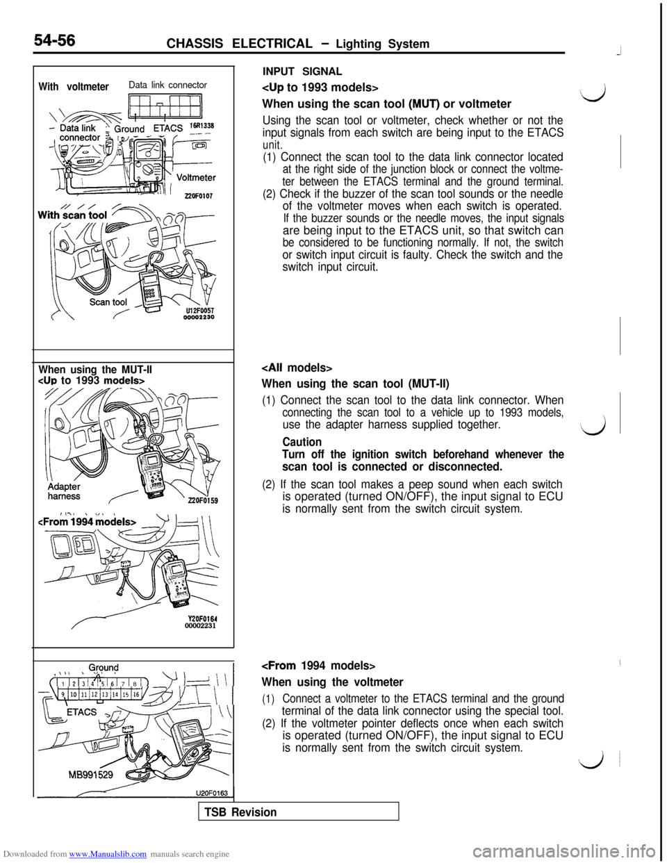
Downloaded from www.Manualslib.com manuals search engine INPUT SIGNALWith voltmeterData link connector
Ii ri7-11
When using the scan tool (MUT) or voltmeter‘d
Using the scan tool or voltmeter, check whether or not the
input signals from each switch are being input to the ETACS
unit.
54-56CHASSIS ELECTRICAL - Lighting System
(1) Connect the scan tool to the data link connector located
at the right side of the junction block or connect the voltme-
ter between the ETACS terminal and the ground terminal.
(2) Check if the buzzer of the scan tool sounds or the needle
of the voltmeter moves when each switch is operated.
If the buzzer sounds or the needle moves, the input signalsare being input to the ETACS unit, so that switch can
be considered to be functioning normally. If not, the switch
or switch input circuit is faulty. Check the switch and the
switch input circuit.
When using the MUT-II
CUP to 1993 models>
Y2OFO16400002231,
0,@y.m$
( 1 1 1 2 1; 1 4% 16 1 7 1 8 / 1
’ 1-d \ \ 1
~~~4i10illi12i13illi15i16v~~~1 \ \ 1U2OFO163
When using the scan tool (MUT-II)
(1) Connect the scan tool to the data link connector. When
connecting the scan tool to a vehicle up to 1993 models,
use the adapter harness supplied together.‘dCaution
Turn off the ignition switch beforehand whenever the
scan tool is connected or disconnected.
(2) If the scan tool makes a peep sound when each switchis operated (turned ON/OFF), the input signal to ECU
is normally sent from the switch circuit system.
When using the voltmeter
(1)Connect a voltmeter to the ETACS terminal and the ground
terminal of the data link connector using the special tool.
(2) If the voltmeter pointer deflects once when each switchis operated (turned ON/OFF), the input signal to ECU
is normally sent from the switch circuit system.
do
TSB Revision
Page 569 of 738
Downloaded from www.Manualslib.com manuals search engine CHASSIS ELECTRICAL - Lighting System
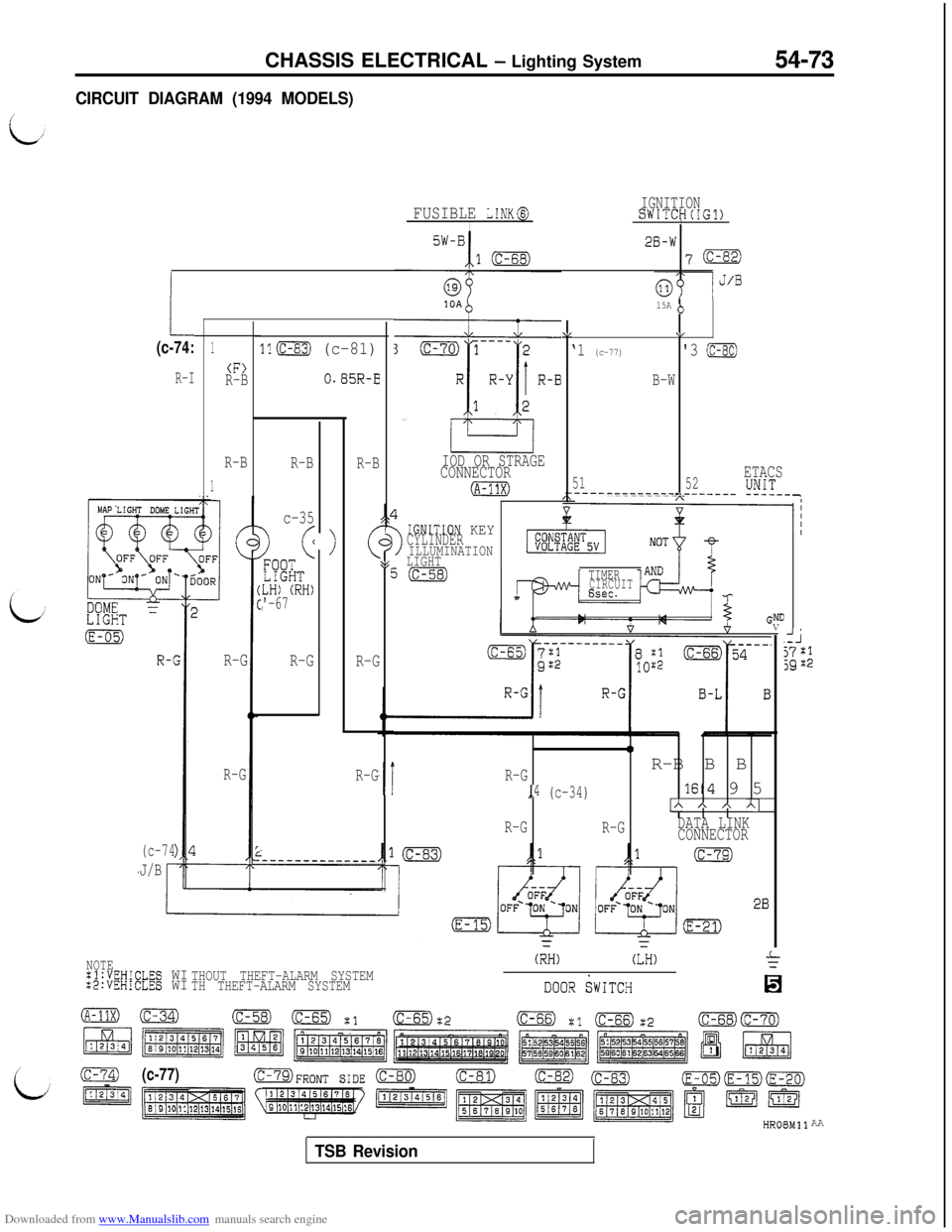
CIRCUIT DIAGRAM (1994 MODELS)54-73
IGNITIONSWITCH(IG1)IFUSIBLE L!NK@I5W-B2B-W
107m
1.
IOD OR STRAGE
CONNECTOR
(A-?1X)
15A (>
\I\/
‘1 (c-77)'3 (c-80)
B-W
51ETACS
__---_---------_____-_ !!1T--,52
(c-74:1
(F>R-B
R-B
1
ll(c-83) (c-81)
O.B5R-ER-I
>
R-B
R-B
c-35
) (<
FQO?LIGHTLH) (RH)'-67,
R-G
R-G
3>
!GNITION KEYCYLINDERILLUMINATION\gLIGHTEi(c-58)TIMERCIRCUIT6sec.
0
,iR-GR-B B B
,,4 (c-34)lE4 9 5
IA A * Al
R-G
R-GDATA LINK
CONNECTOR R-G
R-G
.NDV
AJj7:1jgZ2
(c-74
J/BR-G
NOTE:l:VEHICLES WI:2:VEHiCLES WITHOUT THEFT-ALARM SYSTEM
TH THEFT-ALARM SYSTEM
(RH)(LH)
DooR SWITCH
(c-77)OFRONT SIDE (C-80)(c-81)(c-82)AA
TSB Revision