Variable induction MITSUBISHI 3000GT 1995 2.G Workshop Manual
[x] Cancel search | Manufacturer: MITSUBISHI, Model Year: 1995, Model line: 3000GT, Model: MITSUBISHI 3000GT 1995 2.GPages: 738, PDF Size: 35.06 MB
Page 48 of 738
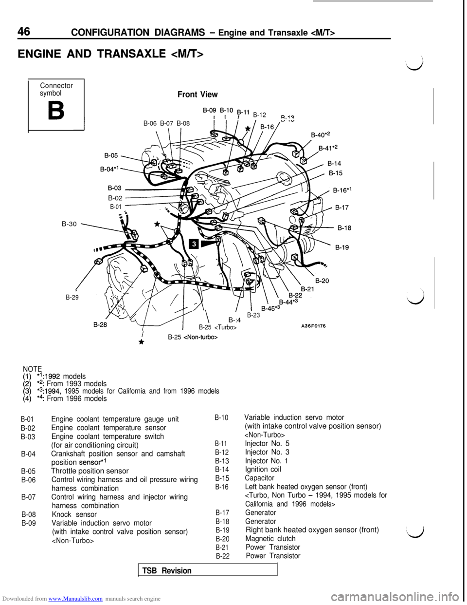
Downloaded from www.Manualslib.com manuals search engine 46CONFIGURATION DIAGRAMS - Engine and Transaxle
ENGINE AND TRANSAXLE
Connector
symbol
B
Front View
B-0: B;lO 53-11B-12R-i?
IB-06 B-07 B-08B-40*’
B-02
------+
B-01B-30
\ 7
I
B-29
- \B-:4B-23
B-25
A36F0176
B-01
B-02
B-03
B-04
B-05
B-06
B-07
B-08
B-09
i*B-25
NOTE
[:I*‘A992 models*2: From 1993 models*s:1994, 1995 models for California and from 1996 models*4: From 1996 models
Engine coolant temperature gauge unit
Engine coolant temperature sensor
Engine coolant temperature switch(for air conditioning circuit)
Crankshaft position sensor and camshaftposition
sensor*’Throttle position sensor
Control wiring harness and oil pressure wiring
harness combination
Control wiring harness and injector wiring
harness combination
Knock sensor
Variable induction servo motor
(with intake control valve position sensor)
B-10
B-11
B-12
B-13
B-14
B-15
B-16
B-17
B-18
B-19
B-20
B-21
B-22
Variable induction servo motor(with intake control valve position sensor)
Injector No. 5
Injector No. 3
Injector No. 1
Ignition coil
Capacitor
Left bank heated oxygen sensor (front)
California and 1996 models>
Generator
GeneratorRight bank heated oxygen sensor (front)
Magnetic clutch
Power Transistor
Power TransistorL)
TSB Revision
Page 50 of 738
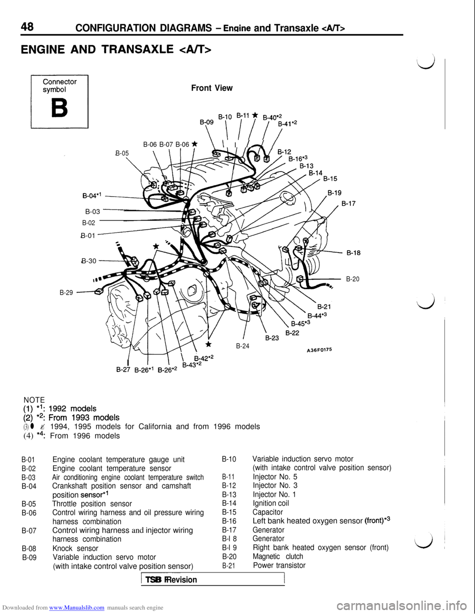
Downloaded from www.Manualslib.com manuals search engine 48CONFIGURATION DIAGRAMS - Ennine and Transaxle
ENGINE AND TRANSAXLE
Front View
By ‘-[ i”i 7741e2
B-06 B-07 B-06 *\ I I /A /
B-05\ \IB-30
-
B-04*’B-03
-
B-02B-01
-
B-29
*B-24A36F0176
/ m \ i-42*2
B-20I
1IB-27 B-26*’ B-26*2 B-43*2
NOTE
[:I 1:: zif ~$$‘~ode~s
(3) l ?1994, 1995 models for California and from 1996 models
(4)
*4:From 1996 models
B-01
B-02
B-03
B-04
B-05
B-06
B-07
B-08
B-09
Engine coolant temperature gauge unit
Engine coolant temperature sensor
Air conditioning engine coolant temperature switch
Crankshaft position sensor and camshaftposition
sensor*’
Throttle position sensor
Control wiring harness and oil pressure wiring
harness combinationControl wiring harness and injector wiring
harness combination
Knock sensor
Variable induction servo motor(with intake control valve position sensor)
B-10
B-11
B-12
B-13
B-14
B-15
B-16
B-17
B-l 8
B-l 9
B-20
B-21
Variable induction servo motor
(with intake control valve position sensor)
Injector No. 5
Injector No. 3
Injector No. 1
Ignition coil
CapacitorLeft bank heated oxygen sensor
(front)*3
Generator
Generator
Right bank heated oxygen sensor (front)
Magnetic clutch
Power transistor
I-- ~~~TSB Revision
Page 89 of 738
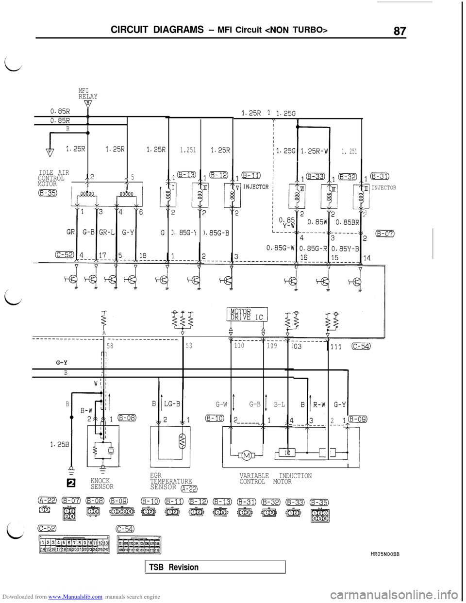
Downloaded from www.Manualslib.com manuals search engine CIRCUIT DIAGRAMS - MFI Circuit
MFIRELAY
0.85R1.25R 1 1.25GI‘10.85RIR0
1.25R1.25R1.25R
IDLE AIRCONTROL..2,\ 5MOTORI\,\r
I f-1
/1.25G 1.25R-W
II I
1. 2511.251
I. 85G-J
1.25R
).85G-B
VV
lm
n INJECTOR
13
i
-I-
iA--__--------_-_--_ ________---_----__
5853110
1091
i-l
G-YI/I IBI II I
WI II I
BG-W1G-B1B-L
------L
G-i
2---_
cl-1
1Emo
II
VARIABLE INDUCTION
CONTROL MOTOR
1.25B
1
0
EGR
TEMPERATURE
SENSOR (~-22)KNOCK
SENSOR
TSB Revision
Page 101 of 738
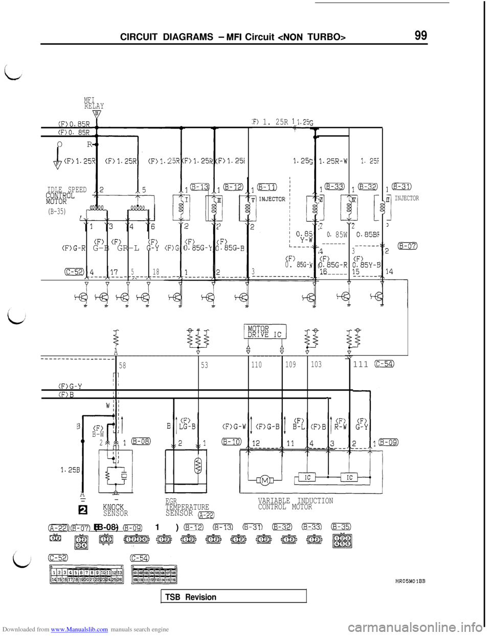
Downloaded from www.Manualslib.com manuals search engine CIRCUIT DIAGRAMS - MFI Circuit
MFIRELAY
:F) 1. 25R 1;$.251(Fj0.85R
(F)O. 85ROR
4F (F>1.25!1.25(
IDLE SPEEDpr&oL
(B-35)rr”
25R 1
i
:F)G ;(F) (F)(F)G-R G-B GR-L 6": (
518-__--_L___=~4---~2- ,\ ,\
d&-&d
?>1.25FFj'l.2511.25R-W1. 25F
l(B-33) j-
7$x
22
0. 85W0.85BF
---------___?3
ti
1a
n INJECTOR
II1
F).85G
I
I
2
:F)).85G-k
(F)0. 85G-'3--------_-___-
A_---____-_--_-__-_------------------
--------------------Y
5853110109103
ri/I(F)G-YI I
(F)BI II,,I.+
I
111 m
w; I
4:
(F>B-W' jE
2d,1 (B-08)
E
'l.25EA
hKNOCKEGRTEMPERATURE
SENSORSENSOR (A-P~)
VARIABLE INDUCTION
CONTROL MOTOR
(B-lo) (B-11) CFm @ml Fm Em-2) Gm (8-35)(2 (8-07) (B-08) (8-09)12
@j~~r@~~@JJl@EJ@J@J
TSB Revision
HROBMO IBB
Page 113 of 738
Downloaded from www.Manualslib.com manuals search engine CIRCUIT DIAGRAMS - MFI Circuit
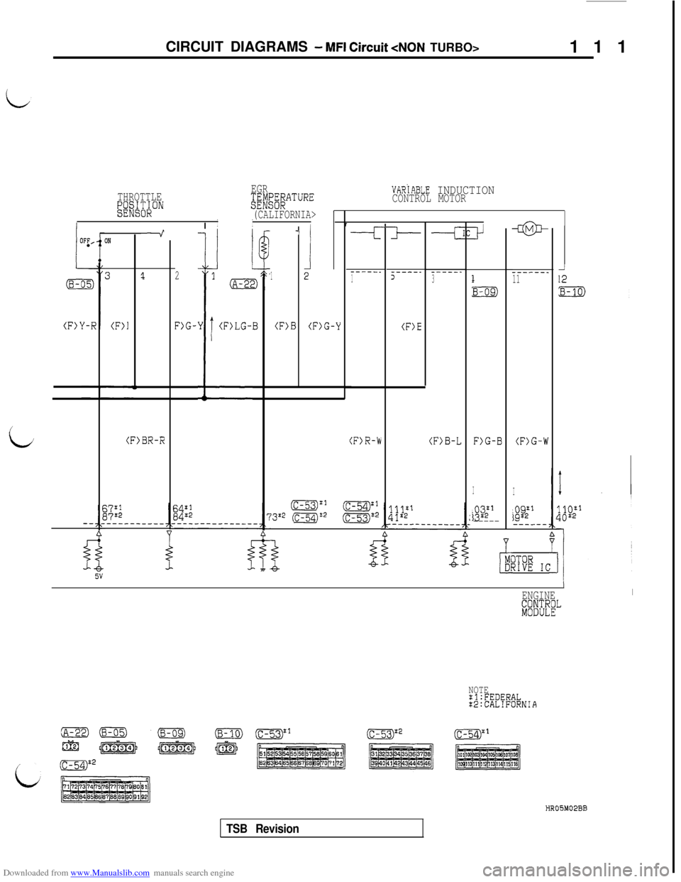
111
VARiABLE INDUCTIONCONTROL MOTOR THROTTLEEGRW3I;;ON&E#g;&ATURE
(CALIFORNIA>IIr-a@-
-----__11
(F)G-W
I
ao9;1*--__--
:
(B-i
(F>‘
2
F>G-
It--I
1
(F>B
-
j’
Yi(F)LG-B
ON
(F>l
?
F>G-B
I
$ij2fl-----
----__1-----_2
(F)E
_----_3
(F)G-Y
i(F>BR-R(F)R-b(F>B-L
13~2 (c-54):2(c-53)= cggl:2
iiB
g:;----------
3TOR?IVE IC
IENGINEI
lsi%~!L
NOTE:l:FEDERAL:2:CALIFORNIA
HROSM02BB
TSB Revision
Page 129 of 738
Downloaded from www.Manualslib.com manuals search engine CIRCUIT DIAGRAMS - MFI Circuit
127 (
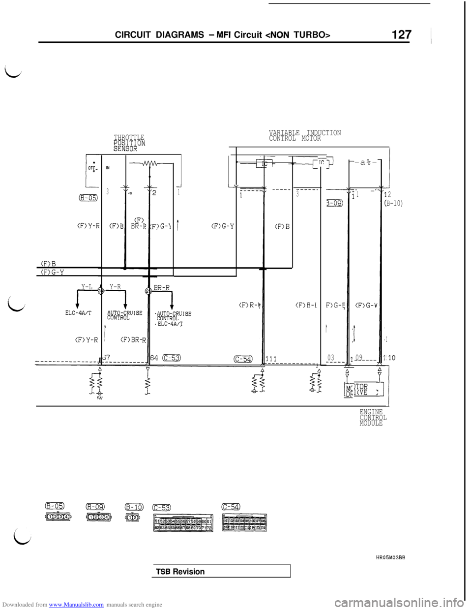
THROTTLE?';;A;;""
(F>Y-R(F)l
(F)B
(F>G-Y
Y-L
/
rELCdA/T
(F>Y-R
IN
3a
(F>BR-I
Y-R
1#;f;~IW~XJISE
(F>BR-
)G-‘I
VARIABLE INDUCTION
CONTROL MOTOR
-i1t-
I(F)G-Y
c
Y
(F)R-$
ELC-4A/T
----_
(F>B
-----_3
(F>B-L
B
i-i!-
3-09)
F)G-E
1
03----_
I-a%-
.----_.1
(F>G-h
t
09------
ITOR!IVEI(
ENGINE
CONTROL
MODULE
1
2
B-10)
I
.lO
!
TSB Revision
Page 137 of 738
Downloaded from www.Manualslib.com manuals search engine CIRCUIT DIAGRAMS - MFI Circuit
135
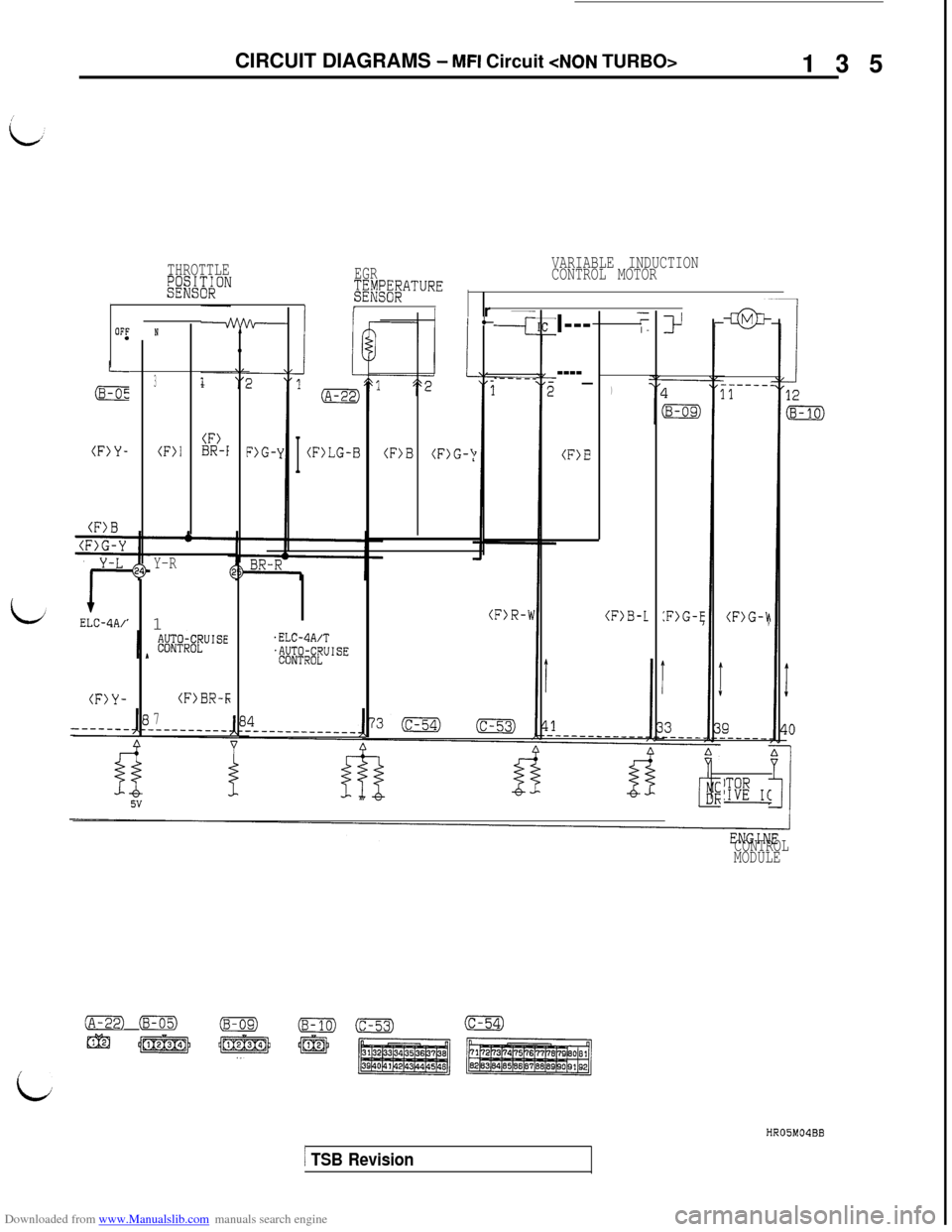
THROTTLEg;;W;;ONEGRVARIABLE INDUCTION
;E;g;EATURECONTROL MOTOR
I/IrIIr
OFfNcI---
l-
)Y
F)G-
+m-
(F>G-h
----_
(F>B(F>B (F)G-!I
(F)LG-B
3
(F>Y-(F)l(F)BR-f.__--_
(F)B-L:F>G-E
(F>B
OG-Y
Y-L
I-ELC-4A/'
Y-R1
(F)R-W
.ELC-4A/T$J~@fU'SE
(F>Y-(F>BR-f;
7
ITOR'IVE IC-
CONTROL
MODULE
(A-22) (B-05)(B-OS)(B-10)0
m I/~) j@+-/ p&
(c-54)
i
HR05M04BB
1 TSB Revision
Page 153 of 738
Downloaded from www.Manualslib.com manuals search engine CIRCUIT DIAGRAMS - MFI Circuit
151 ~
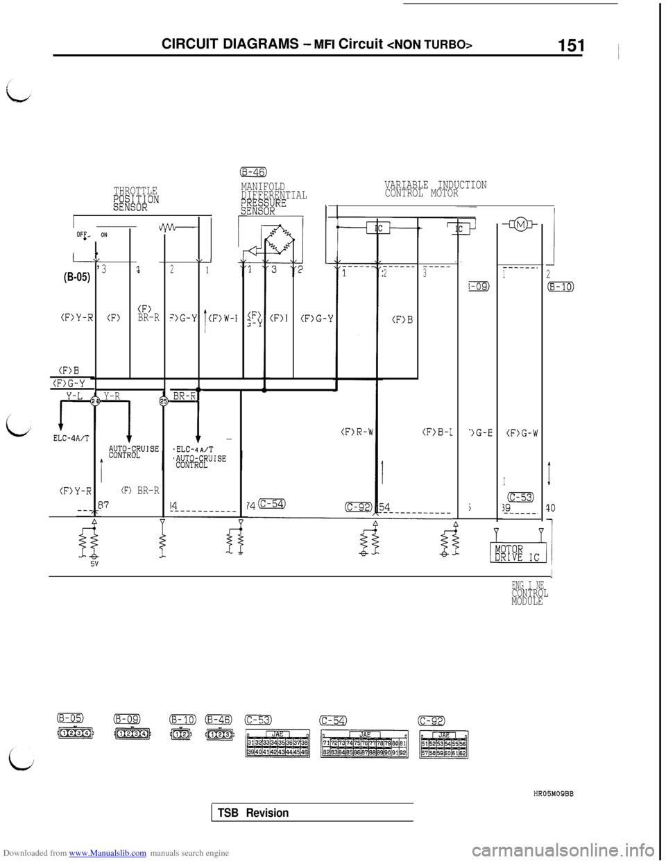
VARIABLE INDUCTION
CONTROL MOTOR MANIFOLD
DIFFERENTIAL
SEE;;;“”
Ii
THROTTLE;&;OE&ON
I
1
2
(8-10)
T
10
i
(F)BR-R
-@-
------.1
1-09)
')G-E(F)G-W
j
I
3gm
-----_.
ITOR7IVE IC
t
OF:,ON
0AL,L-
(B-05)3
(F>Y-F7(F)
(F>B
(F)G-Y24
Y-R
1'#;;#J'SE
(F>l(F>G-Y
(F>R-W
-J1
(F)W-I
A‘2
‘)G-\lI
*m
1.ELC-,4A
(F>Z-Y
-----_2
(F>B
-----3
(F>B-1-
/T
!L-.------
(F) BR-R
17
(F>Y-R-
I5v
IENG I NECONTROL
MODULE
HROBMOSBB
TSB Revision
Page 166 of 738
Downloaded from www.Manualslib.com manuals search engine CIRCUIT DIAGRAMS - MFI Circuit
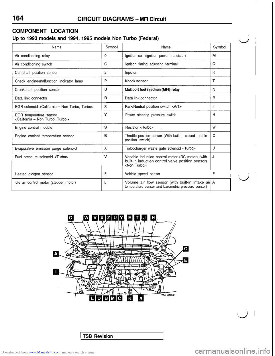
COMPONENT LOCATIONUp to 1993 models and 1994, 1995 models Non Turbo (Federal)
NameSymbol
Air conditioning relay0
Air conditioning switch
Camshaft position sensor
a
Check engine/malfunction indicator lampP
Crankshaft position sensorD
Data link connectorR
EGR solenoid
EGR temperature sensor
Engine control module
Engine coolant temperature sensor
Evaporative emission purge solenoid
Fuel pressure solenoid
Heated oxygen sensorE
idle air control motor (stepper motor)L
Name/ Symbol
Ignition coil (ignition power transistor)
Ignition timing adjusting terminal
Injector
(1
Multrport fuel rnjectron (MFI) relay
ParWNeutral position switch c&T>
Power steering pressure switchH
Resistor
Throttle position sensor (With built-in closed throttleCposition switch)
Turbocharger waste gate solenoid
Variable induction control motor (DC motor) (withJbuilt-in induction control valve position sensor)
Vehicle speed sensorFIVolume air flow sensor (with built-in intake air A
temperature sensor and barometric pressure sensor)
1 TSB Revision
Page 171 of 738
Downloaded from www.Manualslib.com manuals search engine CIRCUIT DIAGRAMS - MFI Circuit169
i
L
iJ
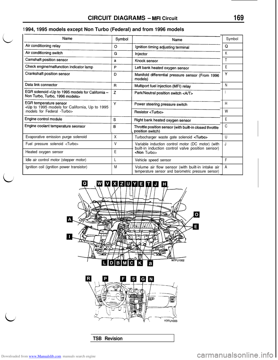
1994, 1995 models except Non Turbo (Federal) and from 1996 models
Evaporative emission purge solenoid
Fuel pressure solenoid
Heated oxygen sensor
Idle air control motor (stepper motor)
Ignition coil (ignition power transistor)
XTurbocharger waste gate solenoid
V
Variable induction control motor (DC motor) (with
Ebuilt-in induction control valve position sensor)
LVehicle speed sensor
MVolume air flow sensor (with built-in intake airtemperature sensor and barometric pressure sensor)Symbol
Q
K
T
E
Y
N
I
H
W
E
C
U
J
F
A
TSB Revision