service MITSUBISHI 380 2005 Workshop Manual
[x] Cancel search | Manufacturer: MITSUBISHI, Model Year: 2005, Model line: 380, Model: MITSUBISHI 380 2005Pages: 1500, PDF Size: 47.87 MB
Page 1237 of 1500
HOW TO USE TROUBLESHOOTING/INSPECTION SERVICE POINTS
GENERAL00-16
INSPECTION SERVICE POINTS FOR A BLOWN
FUSE
M1001013800067
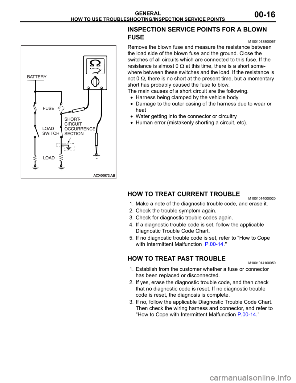
Remove the blown fuse and measure the resistance between
the load side of the blown fuse and the ground. Close the
switches of all circuits which are connected to this fuse. If the
resistance is almost 0
at this time, there is a short some-
where between these switches and the load. If the resistance is
not 0
, there is no short at the present time, but a momentary
short has probably caused the fuse to blow.
The main causes of a short circuit are the following.
Harness being clamped by the vehicle body
Damage to the outer casing of the harness due to wear or
heat
Water getting into the connector or circuitry
Human error (mistakenly shorting a circuit, etc).
HOW TO TREAT CURRENT TROUBLEM1001014000020
1. Make a note of the diagnostic trouble code, and erase it.
2. Check the trouble symptom again.
3. Check for diagnostic trouble codes again.
4. If a diagnostic trouble code is set, follow the applicable
Diagnostic Trouble Code Chart.
5. If no diagnostic trouble code is set, refer to "How to Cope
with Intermittent Malfunction P.00-14."
HOW TO TREAT PAST TROUBLEM1001014100050
1. Establish from the customer whether a fuse or connector
has been replaced or disconnected.
2. If yes, erase the diagnostic trouble code, and then check
that no diagnostic code is reset. If no diagnostic trouble
code is reset, the diagnosis is complete.
3. If no, follow the applicable Diagnostic Trouble Code Chart.
Then check the wiring harness and connector, and refer to
"How to Cope with Intermittent Malfunction P.00-14."
Page 1243 of 1500
PRECAUTIONS BEFORE SERVICE
GENERAL00-22
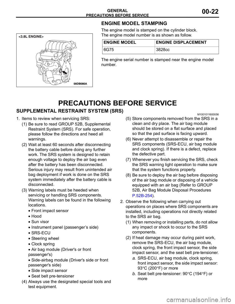
ENGINE MODEL STAMPING
The engine model is stamped on the cylinder block.
The engine model number is as shown as follow.
The engine serial number is stamped near the engine model
number.
PRECAUTIONS BEFORE SERVICE
SUPPLEMENTAL RESTRAINT SYSTEM (SRS)M1001011600056
1. Items to review when servicing SRS:
(1) Be sure to read GROUP 52B, Supplemental
Restraint System (SRS). For safe operation,
please follow the directions and heed all
warnings.
(2) Wait at least 60 seconds after disconnecting
the battery cable before doing any further
work. The SRS system is designed to retain
enough voltage to deploy the air bag even
after the battery has been disconnected.
Serious injury may result from unintended air
bag deployment if work is done on the SRS
system immediately after the battery cable is
disconnected.
(3) Warning labels must be heeded when
servicing or handling SRS components.
Warning labels can be found in the following
locations.
Front impact sensor
Hood
Sun visor
Instrument panel (passenger ’s side)
SRS-ECU
Steering wheel
Clock spring
Air bag module (Driver's or front
passenger's)
Side-airbag module (Driver's side or front
passenger's side)
Side impact sensor
Seat belt pre-tensioner
(4) Always use the designated special tools and
test equipment.(5) Store components removed from the SRS in a
clean and dry place. The air bag module
should be stored on a flat surface and placed
so that the pad surface is facing upward.
(6) Never attempt to disassemble or repair the
SRS components (SRS-ECU, air bag module
and clock spring). If there is a defect, replace
the defective part.
(7) Whenever you finish servicing the SRS, check
the SRS warning light operation to make sure
that the system functions properly.
(8) Be sure to deploy the air bag before disposing
of the air bag module or disposing of a vehicle
equipped with an air bag (Refer to GROUP
52B, Air Bag Module Disposal Procedures
P.52B-254).
2. Observe the following when carrying out
operations on places where SRS components are
installed, including operations not directly related
to the SRS air bag.
(1) When removing or installing parts, do not allow
any impact or shock to occur to the SRS
components.
(2) If heat damage may occur during paint work,
remove the SRS-ECU, the air bag module,
clock spring, the front impact sensor, the side
impact sensor, and the seat belt pre-tensioner.
a.SRS-ECU, air bag module, clock spring,
front impact sensor, the side impact sensor:
93
C (200F) or more
b.Seat belt pre-tensioner: 90
C (194F) or
more ENGINE MODEL ENGINE DISPLACEMENT
6G75 3828cc
Page 1244 of 1500

PRECAUTIONS BEFORE SERVICE
GENERAL00-23
HOW TO PERFORM VEHICLE IDENTIFICATION
NUMBER (VIN) WRITING
M1001011400063
The Vehicle Identification Number (VIN) is stored in the ECU by
the vehicle manufacture. If the VIN to be stored in the ECU is
eliminated fraudulently, the Malfunction Indicator Lamp (Check
Engine Lamp) illuminates and Diagnostic Trouble Code (DTC)
No.P0630 (VIN malfunction) is shown. When the ECU is
replaced, and entry of the VIN necessary due to DTC No.
P0630 (VIN malfunction). Enter the VIN in accordance with the
procedure as follows:
.
WRITING PROCEDURE
Required Special Tools:
Diagnostic Tool (MUT-III)
MB991824: V.C.I.
MB991827: MUT-III USB Cable
MB991910: MUT-III Main Harness A (BLUE)
To prevent damage to DIAGNOSTIC TOOL (MUT-III), always
turn the ignition switch to the "LOCK" (OFF) position
before connecting or disconnecting.
1. Connect Diagnostic Tool to the data link connector.
2. Turn the ignition switch to the "ON" position.
3. Confirm DTC No.P0630 (EEPROM malfunction) is not
shown.
NOTE: When DTC No. P0630 (EEPROM malfunction) is
shown, the VIN cannot be stored even if entered. Therefore,
the troubleshooting is performed when this DTC is shown.
4. Select "Coding" form the menu screen.
5. Select "VIN writing" form the menu screen.
6. Enter the VIN.
7. After entry of the VIN, turn the ignition switch to the "LOCK"
(OFF) position. After ten seconds or more passed, turn to
the "ON" position again.
8. Confirm DTC No.P0630 (VIN malfunction) is not shown.
NOTE: When DTC No.P0630 (VIN malfunction) is shown,
enter the VIN again because that would be not appropriate.
Page 1245 of 1500
PRECAUTIONS BEFORE SERVICE
GENERAL00-24
SERVICING ELECTRICAL SYSTEMM1001011900057
Battery posts, terminals and related accessories con-
tain lead and lead compounds. WASH HANDS AFTER
HANDLING.
1. Note the following before proceeding with working on the
electrical system.
Never perform unauthorized modifications to any electrical
device or wiring. Such modifications might lead to a vehicle
malfunction, over-capacity or short-circuit that could result in
a fire in the vehicle.
Before connecting or disconnecting the negative bat-
tery cable, be sure to turn the ignition switch to the
"LOCK" (OFF) position and turn off the lights (If this is
not done, there is the possibility of semiconductor
parts being damaged).
After completion of the work (and the negative battery
terminals is connected), warm up the engine and allow
it to idle for approximately 10 minutes under the condi-
tions described below in order to stabilize engine con-
trol conditions, and then check to be sure that the idle
is satisfactory.
Engine coolant temperature: 85 to 95C (185 to
203
F)
Lights and all accessories: OFF
Transaxle: "N" or "P" position
Steering wheel: straight-forward position
2. When servicing the electrical system, disconnect the
negative cable terminal from the battery.
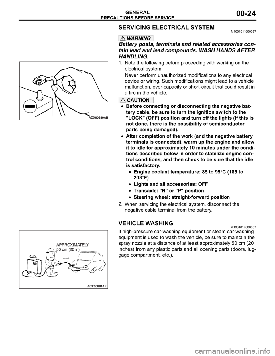
VEHICLE WASHINGM1001012000057
If high-pressure car-washing equipment or steam car-washing
equipment is used to wash the vehicle, be sure to maintain the
spray nozzle at a distance of at least approximately 50 cm (20
inches) from any plastic parts and all opening parts (doors, lug-
gage compartment, etc.).
Page 1246 of 1500
PRECAUTIONS BEFORE SERVICE
GENERAL00-25
APPLICATION OF ANTI-CORROSION AGENTS
AND UNDERCOATS
M1001011000043
Do not to apply oil or grease to the heated oxygen sensor. If
applied, the sensor may malfunction. Protect the heated oxy-
gen sensor with a cover before applying anti-corrosion agent,
etc.
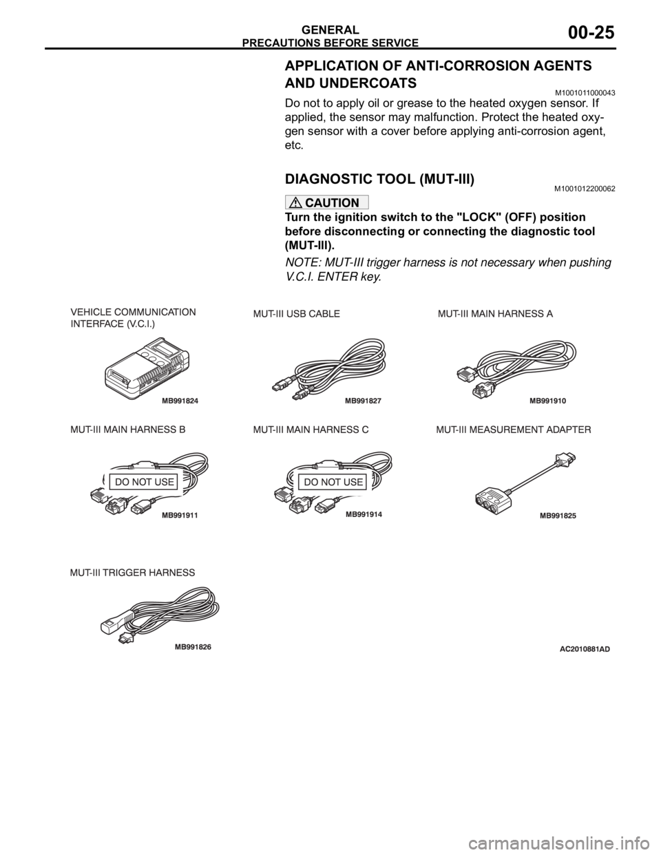
DIAGNOSTIC TOOL (MUT-III)M1001012200062
Turn the ignition switch to the "LOCK" (OFF) position
before disconnecting or connecting the diagnostic tool
(MUT-III).
NOTE: MUT-III trigger harness is not necessary when pushing
V.C.I. ENTER key.
Page 1251 of 1500
TOWING AND HOISTING
GENERAL00-30
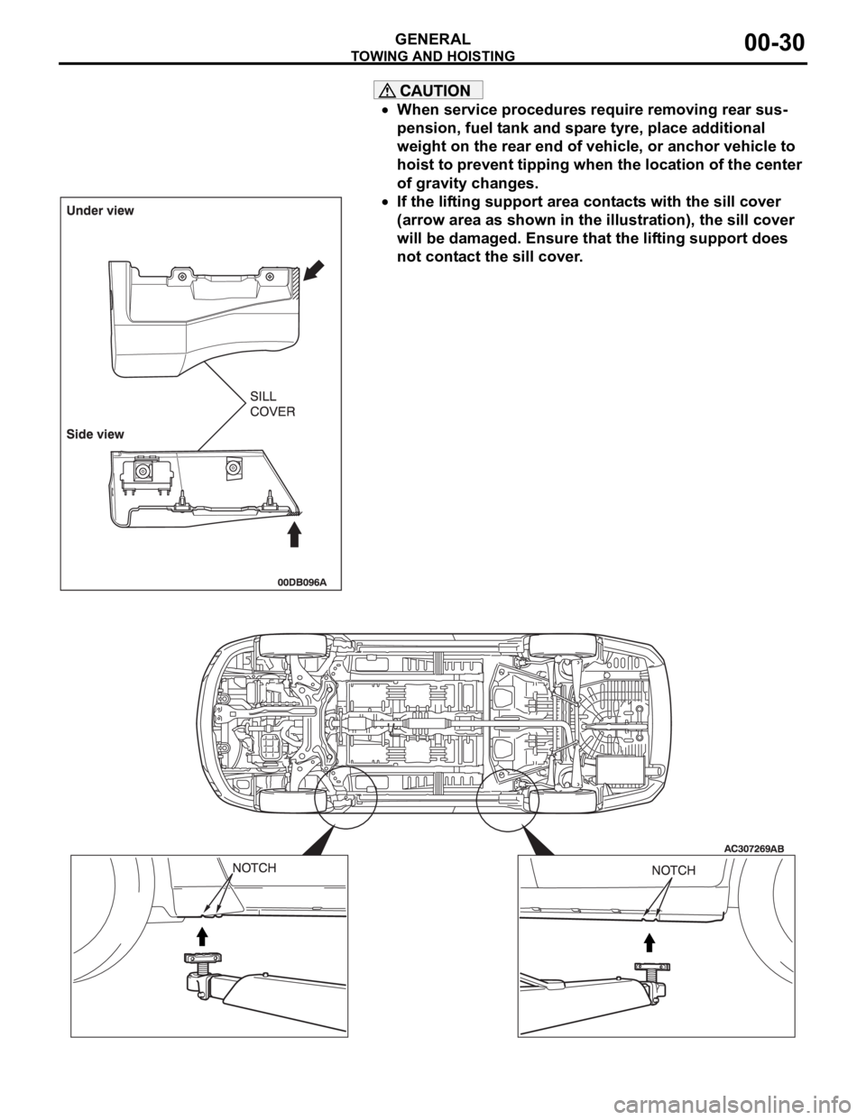
When service procedures require removing rear sus-
pension, fuel tank and spare tyre, place additional
weight on the rear end of vehicle, or anchor vehicle to
hoist to prevent tipping when the location of the center
of gravity changes.
If the lifting support area contacts with the sill cover
(arrow area as shown in the illustration), the sill cover
will be damaged. Ensure that the lifting support does
not contact the sill cover.
Page 1255 of 1500
LUBRICATION AND MAINTENANCE
GENERAL00-34
LUBRICATION AND MAINTENANCEM1001001200336
Maintenance and lubrication service recommenda-
tions have been compiled to provide maximum pro-
tection for the vehicle owner's investment against all
reasonable types of driving conditions. Since these
conditions vary with the individual vehicle owner's
driving habits, the area in which the vehicle is oper-
ated and the type of driving to which the vehicle is
subjected, it is necessary to prescribe lubrication and
maintenance service on a time frequency as well as
mileage interval basis.
Oils, lubricants and greases are classified and
graded according to standards recommended by the
Society of Automotive Engineers (SAE) and the Aus-
tralian Petroleum Institute (API).
MAINTENANCE SCHEDULES
For Information on service maintenance refer to the
"Service handbook".
ENGINE OIL
Tests have shown that laboratory animals
develop skin cancer after prolonged contact with
used engine oil. Accordingly, the potential exists
for humans to develop a number of skin disor-
ders, including cancer, from such exposure to
used engine oil. Therefore, when changing
engine oil, be careful not to touch it as much as
possible. Protective clothing and gloves, that
cannot be penetrated by oil, should be worn. The
skin should be thoroughly washed with soap and
water, or use waterless hand cleaner, to remove
any used engine oil. Do not use petrol, thinners,
or solvents.Either of the following engine oils should be used:
1. Engine oil conforming to the ACEA classification:
"For service A1, A2 or A3.
2. Engine oil conforming to the API classification:
"For service SG" or higher.
FUEL USAGE STATEMENT
Using leaded petrol in this car will damage the
catalytic converters and heated oxygen sensors,
and affect the warranty coverage validity.
This vehicle must use unleaded petrol only.
This vehicle has a fuel filler tube which is especially
designed to accept only the smaller-diameter
unleaded petrol dispensing nozzle.
The 3.8L model is designed to operate on unleaded
petrol having an octane rating (DIN 51607) of 90
RON or higher.
.
PETROL CONTAINING ALCOHOL
Some petrol sold at service stations contain alcohol
although they may not be so identified.
Using fuels containing alcohol is not recommended
unless the nature of the blend can be determined as
being satisfactory, as follows.
Gasohol: A mixture of 10% ethanol and 90%
unleaded gasoline may be used in your vehicle. If
driveability problems are experienced as a result of
using gasohol, it is recommended that the vehicle be
operated on petrol.
Methanol: Do not use petrol containing methanol
(wood alcohol). Using this type of alcohol can result
in vehicle performance deterioration and damage
critical parts in the fuel system components. Fuel
system damage and performance problems resulting
from the use of petrol containing methanol may not
be covered by the new vehicle warranty.
MATERIALS ADDED TO FUEL
Indiscriminate use of fuel system cleaning agents
should be avoided. Many materials intended for gum
and varnish removal may contain highly active sol-
vents or similar ingredients that can be harmful to
gasket and diaphragm materials used in fuel system
component parts.
Page 1258 of 1500
MAINTENANCE SERVICE
GENERAL00-37
MAINTENANCE SERVICE
1. FUEL SYSTEM (TANK, PIPE LINE AND
CONNECTION, AND FUEL TANK FILLER TUBE
CAP) (CHECK FOR LEAKS)
M1001001600312
Check for damage or leakage in the fuel lines and connections.
2. FUEL HOSES (CHECK CONDITION)M1001001700308
1. Inspect the surface of fuel hoses for heat and mechanical
damage. Hard and brittle rubber, cracking, tears, cuts,
abrasions and excessive swelling indicate deterioration of
the rubber.
2. If the fabric casing of the rubber hose is exposed by cracks
and abrasions in the fuel system, the hose should be
replaced.
3. AIR CLEANER FILTER (REPLACE)M1001001800338
The air cleaner element will become dirty during use, reducing
its effectiveness. Replace it with a new one.
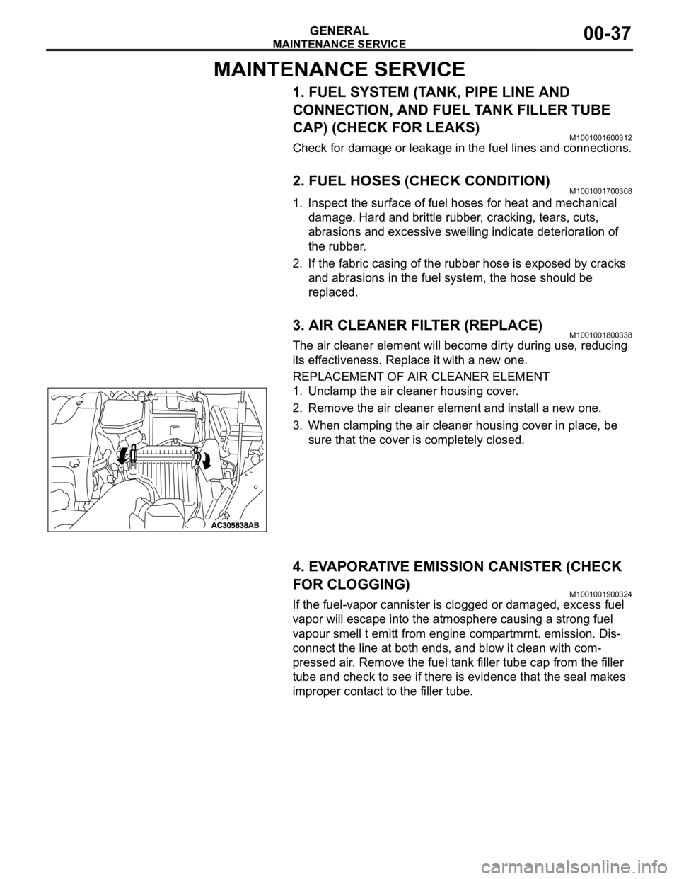
REPLACEMENT OF AIR CLEANER ELEMENT
1. Unclamp the air cleaner housing cover.
2. Remove the air cleaner element and install a new one.
3. When clamping the air cleaner housing cover in place, be
sure that the cover is completely closed.
4. EVAPORATIVE EMISSION CANISTER (CHECK
FOR CLOGGING)
M1001001900324
If the fuel-vapor cannister is clogged or damaged, excess fuel
vapor will escape into the atmosphere causing a strong fuel
vapour smell t emitt from engine compartmrnt. emission. Dis-
connect the line at both ends, and blow it clean with com-
pressed air. Remove the fuel tank filler tube cap from the filler
tube and check to see if there is evidence that the seal makes
improper contact to the filler tube.
Page 1259 of 1500
MAINTENANCE SERVICE
GENERAL00-38
5. SPARK PLUGS (REPLACE)M1001002000346
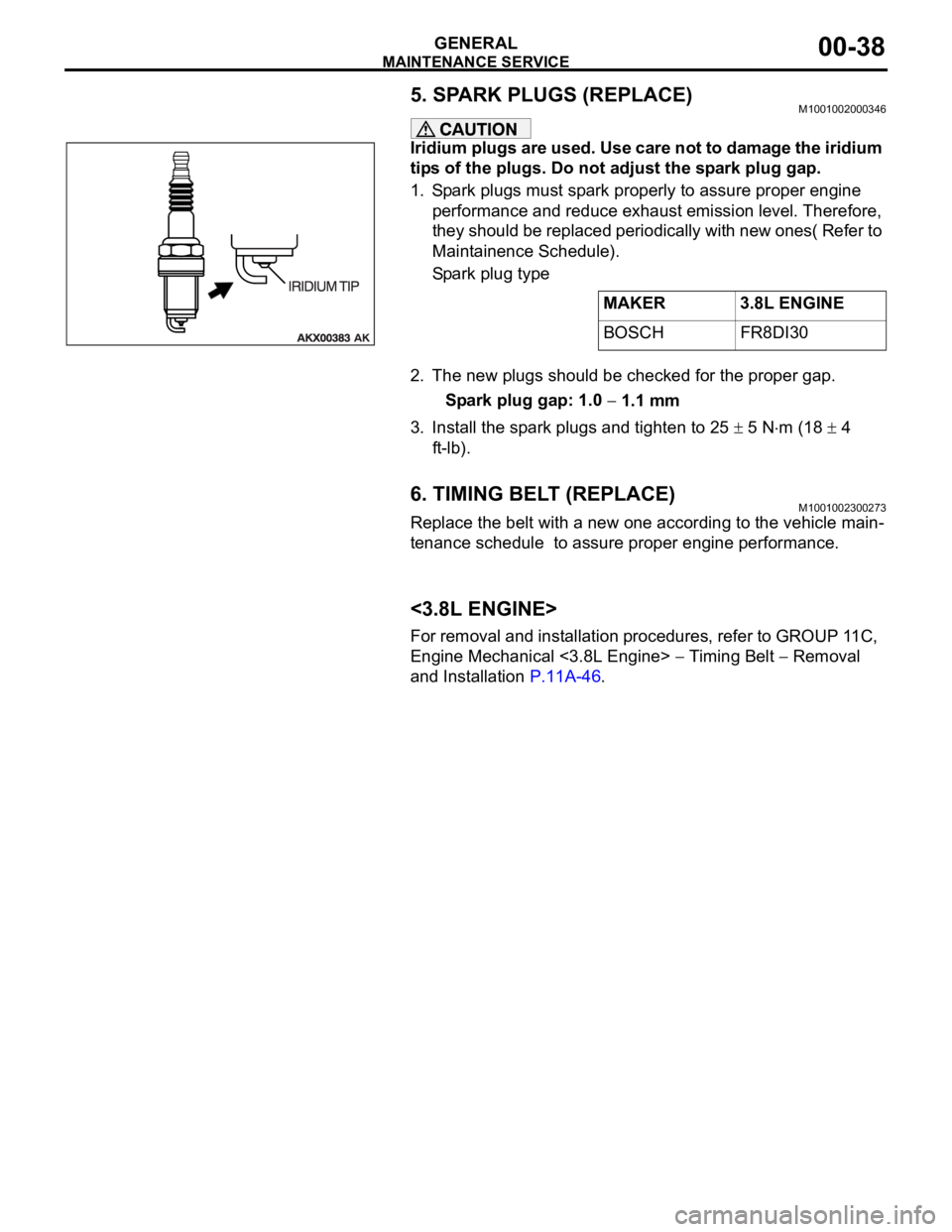
Iridium plugs are used. Use care not to damage the iridium
tips of the plugs. Do not adjust the spark plug gap.
1. Spark plugs must spark properly to assure proper engine
performance and reduce exhaust emission level. Therefore,
they should be replaced periodically with new ones( Refer to
Maintainence Schedule).
Spark plug type
2. The new plugs should be checked for the proper gap.
Spark plug gap: 1.0
1.1 mm
3. Install the spark plugs and tighten to 25
5 Nm (18 4
ft-lb).
6. TIMING BELT (REPLACE)M1001002300273
Replace the belt with a new one according to the vehicle main-
tenance schedule to assure proper engine performance.
<3.8L ENGINE>
For removal and installation procedures, refer to GROUP 11C,
Engine Mechanical <3.8L Engine>
Timing Belt Removal
and Installation P.11A-46.MAKER 3.8L ENGINE
BOSCH FR8DI30
Page 1260 of 1500
MAINTENANCE SERVICE
GENERAL00-39
7. DRIVE BELTS (FOR ALTERNATOR, POWER
STEERING PUMP AND AIR CONDITIONING)
(CHECK)
M1001008700031
ALTERNATOR DRIVE BELT TENSION CHECK
<3.8L ENGINE>
.
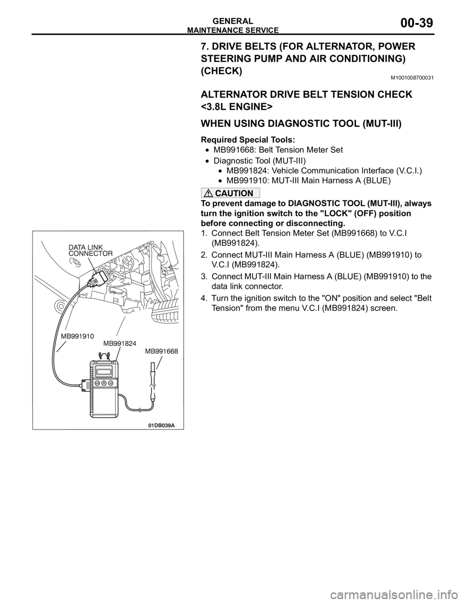
WHEN USING DIAGNOSTIC TOOL (MUT-III)
Required Special Tools:
MB991668: Belt Tension Meter Set
Diagnostic Tool (MUT-III)
MB991824: Vehicle Communication Interface (V.C.I.)
MB991910: MUT-III Main Harness A (BLUE)
To prevent damage to DIAGNOSTIC TOOL (MUT-III), always
turn the ignition switch to the "LOCK" (OFF) position
before connecting or disconnecting.
1. Connect Belt Tension Meter Set (MB991668) to V.C.I
(MB991824).
2. Connect MUT-III Main Harness A (BLUE) (MB991910) to
V.C.I (MB991824).
3. Connect MUT-III Main Harness A (BLUE) (MB991910) to the
data link connector.
4. Turn the ignition switch to the "ON" position and select "Belt
Tension" from the menu V.C.I (MB991824) screen.