fog light MITSUBISHI 380 2005 Workshop Manual
[x] Cancel search | Manufacturer: MITSUBISHI, Model Year: 2005, Model line: 380, Model: MITSUBISHI 380 2005Pages: 1500, PDF Size: 47.87 MB
Page 6 of 1500

GENERAL DESCRIPTION
SIMPLIFIED WIRING SYSTEM (SWS)54B-6
FOG LAMP
.
FOG LAMP
The fog lamps will illuminate only when the fog lamp
switch is operated while the low-beam headlamps
are on.
The fog lamps will be switched off when any of the
following conditions is met. The fog lamps will also
be switched off automatically by headlamp automatic
shutdown function.
When the high-beam headlamps are switched
on, the fog lamps will be switched off. If the
low-beam headlamps are switched on again, the
fog lamps will illuminate again.
When the headlamp switch is turned off while the
tail lamps are on or the tail lamps and headlamps
are off, the fog lamps will be switched off. If the
low-beam headlamps are switched on again, the
fog lamps will not illuminate again.
.
FOG LAMP INDICATOR
At the same time that the fog lamps are illuminated,
the ETACS-ECU sends a signal to illuminate the fog
lamp indicator via the CAN bus line. The combination
meter receives the transmitted signal and turns the
fog lamp indicator on and off.
INTERIOR LAMP
ETACS-ECU makes it possible to force operation of
all ON and OFF lamp switches in the overhead con-
sole (the dome lamp, reading lamp, cargo area lamp,
rear personal lamps, front door lamps, and front foot
lamps). This function is assigned higher priority than
the controls for the interior lamp switch that are per-
formed when the doors are in certain positions.
When the lamps are forced on, the illumination
level is 100% as all interior lamps are switched on
(the dome lamp, reading lamp, cargo area lamp,
rear personal lamps, front door lamps, and front
foot lamps). Even when all lamps are forced on,
the interior lamp automatic shutoff function is
active.
When the lamps are forced off, all interior lamps
are immediately switched off (the dome lamp,
reading lamp, cargo area lamp, rear personal
lamps, front door lamps, and front foot lamps).When the interior lamp switch is at DOOR position,
the ETACS-ECU controls the interior lamps as fol-
lows:
When a door is opened with the ignition switch
off, the interior lamps up to a luminance of 100
percent. When a door is closed, the interior lamps
dims a luminance of 65 percent, and goes off 30
seconds later. However, if the ignition switch is
turned ON or if a door is locked while the interior
lamps is dimming, the dome lamp will go off at
that point.
When a door is opened with the ignition switch
ON, the interior lamps up at a luminance of 100
percent. When all doors are closed, the interior
lamps go off.
When the ignition key is removed with all doors
closed, the interior lamps up at a luminance of
100 percent, and goes off 30 seconds later. How-
ever, if the ignition key is inserted again or if a
door is locked while the interior lamps is lighting,
the interior lamps will go off at that point.
To check keyless entry operations more easily,
the interior lamps will flash twice when doors are
locked. When doors are unlocked, the interior
lamps up at a luminance of 100 percent, and
goes off 15 seconds later.
INTERIOR LAMP AUTOMATIC
SHUTDOUN FUNCTION
Illuminated interior lamps such as the front dome
lamp, etc. (all lamps using the dome lamp fuse as the
power supply) will automatically go off in the follow-
ing conditions to prevent the battery from discharging
as a result of forgetting to turn off the lamps or
incomplete closing of the door.
When the ignition switch is turned off and more
than 30 minutes pass by with the interior lamp
illuminated, the interior lamps will go off automati-
cally.
When the ignition switch is turned off and one of
the door switches remains open for 30 minutes
continuously, the interior lamps will go off auto-
matically.
Page 17 of 1500

SWS DIAGNOSIS
SIMPLIFIED WIRING SYSTEM (SWS)54B-17
ETACS
NOTE: For item No.43, the diagnostic tool
MB991958 (MUT-III Sub Assembly) also displays
"ON" when the lamp reminder tone alarm or the seat
belt tone alarm function is triggered.
.
CHECK
ITEMITEM NO. DISPLAY ON
DIAGNOSTIC
TOOLCHECK CONDITION NORMAL
CONDITION
Tone alarm 43 BUZZER When requirements for sounding each
warning tone alarm are not satisfiedOFF
Front fog
lamps36 F.FOG LAMP
1. Lighting switch: HEAD
2. Fog lamp switch: ONON
Other than the condition above OFF
Driver’s door
switch32 FRONT DOOR
SWDriver’s door switch and Front passenger’s
door switch is on ON
Driver’s door switch and Front passenger’s
door switch is offOFF
Headlamp
automatic
shutoff
function35 H/L AUTO-CUT
1. Lighting switch: Other than OFF
2. Ignition switch: from ON or START to
LOCK (OFF) or ACC
3. Front door switch: ON (front door open) OFF to ON (after
approximately one
second)
When requirements for the headlamp
automatic shutoff are not satisfiedOFF
Ignition
switch (ACC)31 IG SW (ACC) Ignition switch: ACC or ON ON
Ignition switch: LOCK (OFF) or START OFF
Ignition
switch (IG1)30 IG SW (IG1) Ignition switch: ON or START ON
Ignition switch: LOCK (OFF) or ACC OFF
Windshield
intermittent
wiper interval37 INT WIPE
TIME1. Ignition switch: ACC or ON
2. Operate the intermittent wiper control,
and change the wiper intervalThe diagnostic tool
MB991958
(MUT-III Sub
Assembly)
displays
intermittent wiper
interval in
response to the
intermittent wiper
control positions.
Page 22 of 1500

SWS DIAGNOSIS
SIMPLIFIED WIRING SYSTEM (SWS)54B-22
NOTE: When checking the input signals (off, tail,
low-beam or high-beam), turn the ignition switch to
the "ON" position in order to disable the headlamp
automatic shutoff function. However, since the
headlamp operation does not depend on the ignition
switch positions, the diagnostic tool MB991958
(MUT-III Sub Assembly) does not display the title "IGNITION SWITCH". HEADLAMP
LO00 Headlight switch
HEADLAMP SW (COLUMN
ECU)ON
03 Passing lamp
switchPASSING SW (COLUMN
ECU)OFF
30 Ignition switch
(IG1)IG SW (IG1) (ETACS ECU) ON or OFF
35 Headlight
automatic shutoff
functionH/L AUTO-CUT (ETACS
ECU)OFF
70 Response by the
front-ECUFRONT ECU ACK (FRONT
ECU)NORMAL ACK
PASSING
LAMP03 Passing lamp
switchPASSING SW (COLUMN
ECU)ON
70 Response by the
front-ECUFRONT ECU ACK (FRONT
ECU)NORMAL ACK or HI-BEAM
ACK
F.FOG LAMP 00 Headlight switch
HEADLAMP SW (COLUMN
ECU)ON
36 Front fog lamp
switchF.FOG LAMP (COLUMN
ECU)ON
35 Headlight
automatic shutoff
functionH/L AUTO-CUT (ETACS
ECU)OFF
30 Ignition switch
(IG1)IG SW (IG1) (ETACS ECU) ON or OFF
70 Response by the
front-ECUFRONT ECU ACK (FRONT
ECU)NORMAL ACK or HI-BEAM
ACK
TAIL LAMP 00 Headlight switch
HEADLAMP SW (COLUMN
ECU)OFF
01 Tail lamp switch TAILLAMP SW (COLUMN
ECU)ON
03 Passing lamp
switchPASSING SW (COLUMN
ECU)OFF
30 Ignition switch
(IG1)IG SW (IG1) (ETACS ECU) ON or OFF
35 Headlight
automatic shutoff
functionH/L AUTO-CUT (ETACS
ECU)OFF
70 Response by the
front-ECUFRONT ECU ACK (FRONT
ECU)NORMAL ACK ITEM ITEM NO. INPUT SIGNAL DISPLAY ON
DIAGNOSTIC TOOLNORMAL CONDITION
Page 59 of 1500

SYMPTOM CHART
SIMPLIFIED WIRING SYSTEM (SWS)54B-59
Headlamp and
taillampGeneral description concerning the headlamp and
taillampP.54B-257
The taillights do not illuminate normally. H-1
P.54B-260
The headlamps (low-beam) do not illuminate
normally.H-2
P.54B-264
The headlamps (high-beam) do not illuminate
normally.H-3
P.54B-268
When the passing switch is turned "ON," the
headlamps (low-beam or high-beam) do not
illuminate.H-4
P.54B-271
Headlights do not illuminate when the lighting
switch is at "TAIL," and "PASSING" position, but
illuminate at low-beam when the switch is at
"HEAD" position. At this position, the headlamps
cannot be changed to high beam by operating the
dimmer switch.H-5
P.54B-273
The taillamps, the position lamps, front parking
lamps or the license plate lamp do not illuminate.H-6
P.54B-275
One of the headlamps does not illuminate. H-7
P.54B-290
The high-beam indicator lamp does not illuminate. H-8
P.54B-301
Headlamp automatic shutoff function does not
work normally.H-9
P.54B-305
Headlamp dimmer switch automatic resetting
function does not work normally.H-10
P.54B-308
Flasher timer General description concerning the flasher timer
P.54B-309
Turn-signal lamps do not flash when the
turn-signal lamp switch is turned on.I-1
P.54B-310
Hazard warning lamps do not flash when the
hazard warning lamp switch is turned on.I-2
P.54B-314
One of the turn-signal lamps does not illuminate. I-3
P.54B-316
The turn-signal lamp indicator does not illuminate
normally.I-4
P.54B-335
Fog lamp General description concerning the fog lamps
P.54B-339
Fog lamps do not illuminate when the fog lamp
switch is turned on.J-1
P.54B-340
Fog lamps do not go out when the headlamps
(low-beam) are turned off while the fog lamps are
on.J-2
P.54B-345
One of the fog lamps does not illuminate. J-3
P.54B-345
The fog lamp indicator does not illuminate
normally.J-4
P.54B-350 SYSTEM SYMPTOM INSPECTION
PROCEDUREREFERENCE
PA G E
Page 340 of 1500

SYMPTOM PROCEDURES
SIMPLIFIED WIRING SYSTEM (SWS)54B-340
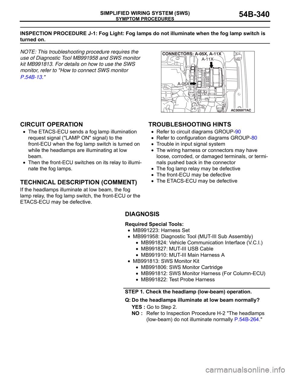
INSPECTION PROCEDURE J-1: Fog Light: Fog lamps do not illuminate when the fog lamp switch is
turned on.
NOTE: This troubleshooting procedure requires the
use of Diagnostic Tool MB991958 and SWS monitor
kit MB991813. For details on how to use the SWS
monitor, refer to "How to connect SWS monitor
P.54B-13."
.
CIRCUIT OPERATION
The ETACS-ECU sends a fog lamp illumination
request signal ("LAMP ON" signal) to the
front-ECU when the fog lamp switch is turned on
while the headlamps are illuminating at low
beam.
Then the front-ECU switches on its relay to illumi-
nate the fog lamps.
.
TECHNICAL DESCRIPTION (COMMENT)
If the headlamps illuminate at low beam, the fog
lamp relay, the fog lamp switch, the front-ECU or the
ETACS-ECU may be defective.
.
TROUBLESHOOTING HINTS
Refer to circuit diagrams GROUP-90
Refer to configuration diagrams GROUP-80
Trouble in input signal system
The wiring harness or connectors may have
loose, corroded, or damaged terminals, or termi-
nals pushed back in the connector
The fog lamp relay may be defective
The front-ECU may be defective
The ETACS-ECU may be defective
DIAGNOSIS
Required Special Tools:
MB991223: Harness Set
MB991958: Diagnostic Tool (MUT-III Sub Assembly)
MB991824: Vehicle Communication Interface (V.C.I.)
MB991827: MUT-III USB Cable
MB991910: MUT-III Main Harness A
MB991813: SWS Monitor Kit
MB991806: SWS Monitor Cartridge
MB991812: SWS Monitor Harness (For Column-ECU)
MB991822: Test Probe Harness
STEP 1. Check the headlamp (low-beam) operation.
Q: Do the headlamps illuminate at low beam normally?
YES : Go to Step 2.
NO : Refer to Inspection Procedure H-2 "The headlamps
(low-beam) do not illuminate normally P.54B-264."
Page 341 of 1500

SYMPTOM PROCEDURES
SIMPLIFIED WIRING SYSTEM (SWS)54B-341
STEP 2. Check the input signal by using "FUNCTION
DIAG." menu of the SWS monitor.
Set each switch to the following condition before checking input
signal from the fog lamp switch:
Ignition switch: ON
Fog lamp switch: ON
NOTE: Turn the ignition switch to the "ON" position in order to
disable the headlamp automatic shutdown function.
To prevent damage to Diagnostic Tool MB991958, always
turn the ignition switch to the "LOCK" (OFF) position
before connecting or disconnecting Diagnostic Tool
MB991958. Connect special tool MB991910 before con-
necting special tool MB991812. Be sure to connect special
tool MB991806 after turning on special tool MB991824.
(1) Connect the special tool. Refer to "How to connect SWS
monitor P.54B-13."
(2) Operate Diagnostic Tool MB991958 according to the
procedure below to display "F.FOG."
a. Select "Interactive Diagnosis."
b. Select "System select."
c. Select "SWS."
d. Select "SWS MONITOR."
e. Select "Function Diag."
f. Select "LIGHTING."
g. Select "F.FOG."
(3) Check that normal conditions are displayed for the items
described in the table below.
Q: Does the Diagnostic Tool MB991958 display the items
"IG SW (IG1)" and "F.FOG LAMP" as normal condition?
Normal conditions are displayed for all the items : Go to
St e p 3 .
Normal condition is not displayed for "IG SW (IG1)" :
Refer to Inspection Procedure M-2 "ETACS-ECU
does not receive any signal from the ignition switch
(IG1) P.54B-408."
Normal condition is not displayed for "F.FOG LAMP" :
Refer to Inspection Procedure M-3 "ETACS-ECU
does not receive any signal from the fog lamp switch
P.54B-410." ITEM NO. ITEM NAME NORMAL CONDITION
ITEM 30 IG SW (IG1) ON
ITEM 36 F.FOG LAMP ON
Page 345 of 1500

SYMPTOM PROCEDURES
SIMPLIFIED WIRING SYSTEM (SWS)54B-345
INSPECTION PROCEDURE J-2: Fog Light: Fog lamps do not go out when the headlamps (low-beam)
are turned off while the fog lamps are on.
.
TECHNICAL DESCRIPTION (COMMENT)
If the trouble above occurs, the front-ECU may be
defective.
.
TROUBLESHOOTING HINT
Refer to circuit diagrams GROUP-90
Refer to configuration diagrams GROUP-80
The front-ECU may be defective
DIAGNOSIS
Replace the front-ECU.
The fog lamps should go out when the headlamps (low-beam)
are turned off while the fog lamps are on.
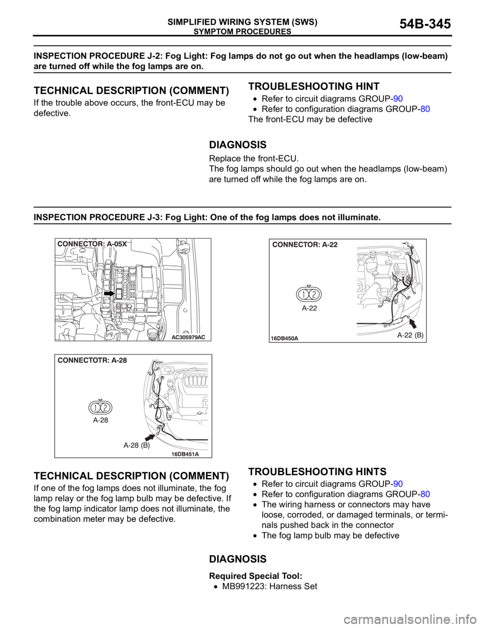
INSPECTION PROCEDURE J-3: Fog Light: One of the fog lamps does not illuminate.
.
TECHNICAL DESCRIPTION (COMMENT)
If one of the fog lamps does not illuminate, the fog
lamp relay or the fog lamp bulb may be defective. If
the fog lamp indicator lamp does not illuminate, the
combination meter may be defective.
.
TROUBLESHOOTING HINTS
Refer to circuit diagrams GROUP-90
Refer to configuration diagrams GROUP-80
The wiring harness or connectors may have
loose, corroded, or damaged terminals, or termi-
nals pushed back in the connector
The fog lamp bulb may be defective
.
DIAGNOSIS
Required Special Tool:
MB991223: Harness Set
Page 484 of 1500

CHECK AT ECU TERMINAL
SIMPLIFIED WIRING SYSTEM (SWS)54B-484
FRONT-ECU
NOTE: Terminal voltages cannot be measured as the
front-ECU is installed directly on the relay box.
Therefore, this information is only for reference.
TERMINAL
NO.INSPECTION ITEM INSPECTION CONDITION NORMAL VALUE
1 Output to fog lamp relay When the fog lamps are on Battery positive voltage
2 Output to headlamp (high-beam) When headlights (high-beam)
are onBattery positive voltage
3, 4 Battery power supply (for
headlamp)Always Battery positive voltage
5 Battery power supply (for
taillamp)Always Battery positive voltage
6 Output to headlamp (low-beam) When headlights (low-beam) are
onBattery positive voltage
7 Battery power supply (for ECU) Always Battery positive voltage
8 Output to taillamps When taillamps are on Battery positive voltage
9
11
21 Output to windshield washer When windshield washer is on Battery positive voltage
22 SWS communication line Always 0
12 V (pulse signal)
23 Input of automatic stop signal to
windshield wiperWhen windshield wiper is on Battery positive voltage
24 Power supply to ignition switch
(ACC)Ignition switch: "ACC" Battery positive voltage
25 Input of backup signal from
headlamp switchHeadlamp switch: ON0 V
26 Input of backup signal to
windshield wiperWindshield low-speed wiper
switch or windshield high-speed
wiper switch: ON0 V
27 Output to windshield wiper
(low-speed)When windshield wiper is on (at
low speed)Battery positive voltage
28 Output to windshield wiper
(high-speed)When windshield wiper is on (at
high speed)Battery positive voltage
30 Power supply to ignition switch
(IG2)Ignition switch: "ON" Battery positive voltage
31 Ground Always 0 V
Page 566 of 1500

FLOOR, SEAT AND ROOF
CONFIGURATION DIAGRAMS80-17
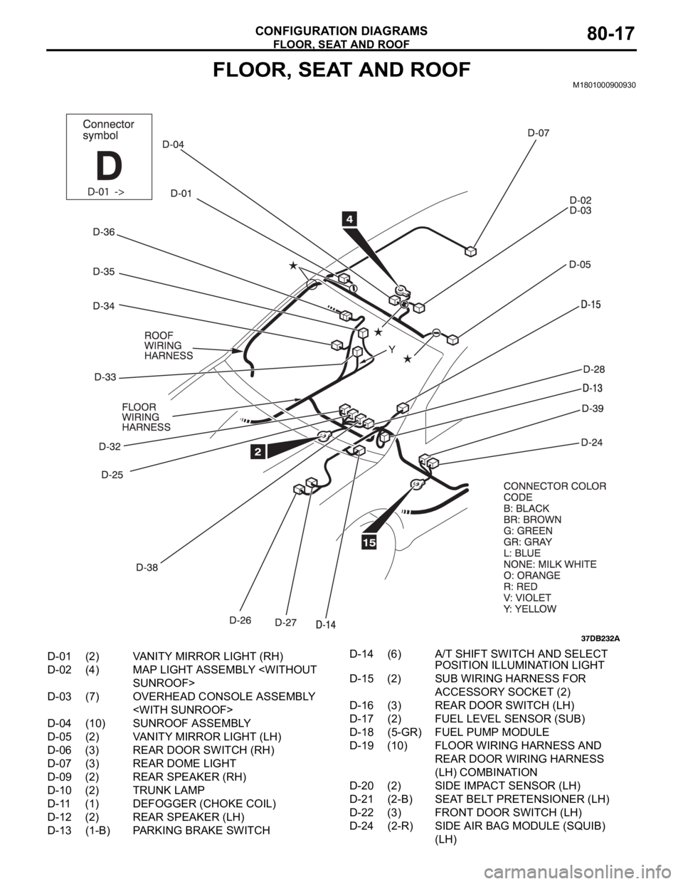
FLOOR, SEAT AND ROOFM1801000900930
D-01 (2) VANITY MIRROR LIGHT (RH)
D-02 (4) MAP LIGHT ASSEMBLY
D-03 (7) OVERHEAD CONSOLE ASSEMBLY
D-04 (10) SUNROOF ASSEMBLY
D-05 (2) VANITY MIRROR LIGHT (LH)
D-06 (3) REAR DOOR SWITCH (RH)
D-07 (3) REAR DOME LIGHT
D-09 (2) REAR SPEAKER (RH)
D-10 (2) TRUNK LAMP
D-11 (1) DEFOGGER (CHOKE COIL)
D-12 (2) REAR SPEAKER (LH)
D-13 (1-B) PARKING BRAKE SWITCHD-14 (6) A/T SHIFT SWITCH AND SELECT
POSITION ILLUMINATION LIGHT
D-15 (2) SUB WIRING HARNESS FOR
ACCESSORY SOCKET (2)
D-16 (3) REAR DOOR SWITCH (LH)
D-17 (2) FUEL LEVEL SENSOR (SUB)
D-18 (5-GR) FUEL PUMP MODULE
D-19 (10) FLOOR WIRING HARNESS AND
REAR DOOR WIRING HARNESS
(LH) COMBINATION
D-20 (2) SIDE IMPACT SENSOR (LH)
D-21 (2-B) SEAT BELT PRETENSIONER (LH)
D-22 (3) FRONT DOOR SWITCH (LH)
D-24 (2-R) SIDE AIR BAG MODULE (SQUIB)
(LH)
Page 579 of 1500

CIRCUIT DIAGRAMS90-2
AUTOMATIC AIR CONDITIONING
SYSTEM . . . . . . . . . . . . . . . . . . . . . . .90-71
WINDSHIELD WIPER AND WASHER90-75
REAR WINDOW DEFOGGER . . . . . .90-78
REMOTE CONTROLLED MIRROR . .90-79
AUDIO SYSTEM . . . . . . . . . . . . . . . .90-80
ACCESSORY SOCKET . . . . . . . . . . .90-82
CLOCK DISPLAY . . . . . . . . . . . . . . .90-83
MULTI-CENTER DISPLAY . . . . . . . .90-84
SUNROOF . . . . . . . . . . . . . . . . . . . . .90-87
AUTO-CRUISE CONTROL SYSTEM90-89
ANTI-LOCK BRAKING SYSTEM (ABS)
ANTI-LOCK BRAKING SYSTEM (ABS)
SYSTEM (SRS) . . . . . . . . . . . . . . . . . .90-99
ENGINE IMMOBILISER SYSTEM . . .90-103
POWER SEAT WITH MEMORY
(DRIVER). . . . . . . . . . . . . . . . . . . . . . .90-104
POWER SEAT (8-WAY)
(DRIVER AND PASSENGER) . . . . . .90-106
POWER SEAT [(6-WAY) DRIVER] . .90-108
FORGOTTEN KEY PREVENTION
FUNCTION . . . . . . . . . . . . . . . . . . . . .90-109
LIGHTING MONITOR TONE ALARM90-111
IGNITION KEY REMINDER TONE
ALARM . . . . . . . . . . . . . . . . . . . . . . . .90-112
SEAT BELT WARNING TONE
ALARM . . . . . . . . . . . . . . . . . . . . . . . .90-113
DOOR AJAR WARNING TONE
ALARM . . . . . . . . . . . . . . . . . . . . . . . .90-115
RHEOSTAT . . . . . . . . . . . . . . . . . . . . .90-118
CONTROLLER AREA NETWORK
(CAN) . . . . . . . . . . . . . . . . . . . . . . . . .90-119