fuses MITSUBISHI 380 2005 Workshop Manual
[x] Cancel search | Manufacturer: MITSUBISHI, Model Year: 2005, Model line: 380, Model: MITSUBISHI 380 2005Pages: 1500, PDF Size: 47.87 MB
Page 10 of 1500

SWS DIAGNOSIS
SIMPLIFIED WIRING SYSTEM (SWS)54B-10
SWS DIAGNOSIS
GENERAL DESCRIPTION
BEFORE CARRYING OUT TROUBLESHOOTINGM1549014700710
Before carrying out troubleshooting, check the fol-
lowing two items.
Make sure that the ETACS-ECU, the junction
block (J/B), the front-ECU and the engine com-
partment relay box are connected securely.
Make sure that fuses and fusible links related to
relevant systems are not blown.
Refer to circuit diagrams GROUP-90
Refer to configuration diagrams GROUP-80
DIAGNOSTIC FUNCTIONM1549028900245
ON-BOARD DIAGNOSTICS
If an error occurs in the ECU or the SWS or CAN
communication line which performs the SWS or CAN
communication, the DTC is memorized in
ETACS-ECU. The DTCs have 11 items. The DTCs
are checked to connect diagnostic tool MB991958
(MUT-III sub assembly). The memorised DTCs are
not erased even if the ignition switch is turned to the
LOCK (OFF) position. The DTCs are erased to oper-
ate diagnostic tool MB991958 (MUT-III sub assem-
bly).NOTE:
*1: For vehicles that do not have a sunroof,
the diagnosis code is always sent but it does not indi-
cate a problem.
NOTE:
*2: The diagnosis code for the current prob-
lem is not sent.
NOTE:
*3: For vehicles that do not have a multi cen-
ter display (middle grade type), the diagnosis code is
always sent but it does not indicate a problem.
HOW TO CONNECT THE DIAGNOSTIC TOOL
(MUT-III)
Required Special Tools:
MB991958: DIAGNOSTIC TOOL (MUT-III Sub Assembly)
MB991824: Vehicle Communication Interface (V.C.I.)
MB991827: MUT-III USB Cable
MB991910: MUT-III Main Harness A DTC CODE TROUBLE CONTENT
001 or U1700 Malfunction of SWS communication line or ETACS-ECU
002 or U1701 Malfunction of column switch
003 or U1702 Malfunction of front-ECU
004
*1 or U1073Malfunction of sunroof-ECU
010
*2 or U1073Bus Off
011 or U1100 Engine ECU time-out
012 or U1101 A/T ECU time-out
013 or U1110 A/C-ECU time-out
014 or U1108 Combination meter time-out
015
*3 or U1111Multi center display unit time-out
021 or U1128 Failure information on combination meter
Page 881 of 1500

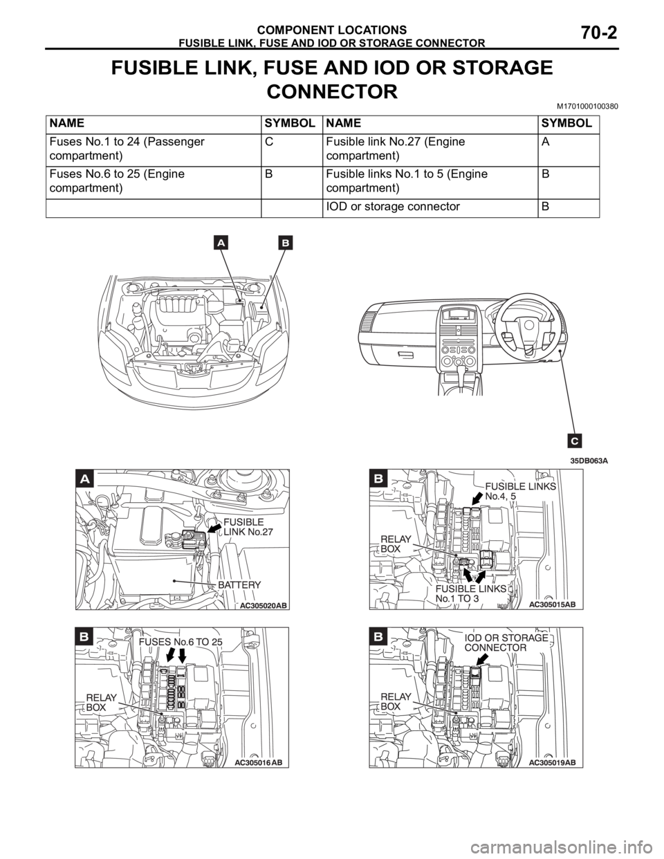
FUSIBLE LINK, FUSE AND IOD OR STORAGE CONNECTOR
COMPONENT LOCATIONS70-2
FUSIBLE LINK, FUSE AND IOD OR STORAGE
CONNECTOR
M1701000100380
NAME SYMBOL NAME SYMBOL
Fuses No.1 to 24 (Passenger
compartment)C Fusible link No.27 (Engine
compartment)A
Fuses No.6 to 25 (Engine
compartment)B Fusible links No.1 to 5 (Engine
compartment)B
IOD or storage connector B
Page 902 of 1500

00E-1
GROUP 00E
GENERAL
CONTENTS
HARNESS CONNECTOR
INSPECTION . . . . . . . . . . . . . . . . . . .00E-2
HOW TO DIAGNOSE . . . . . . . . . . . . .00E-2
HOW TO DIAGNOSE . . . . . . . . . . . . . . . . . 00E-2
TROUBLESHOOTING STEPS . . . . . . . . . . 00E-3
INFORMATION FOR DIAGNOSIS . . . . . . . 00E-3
INSPECTION . . . . . . . . . . . . . . . . . . . . . . . 00E-4INSPECTION INSTRUMENTS . . . . . . . . . . 00E-5
CHECKING FUSES . . . . . . . . . . . . . . . . . . . 00E-6
CHECKING SWITCHES . . . . . . . . . . . . . . . 00E-7
CHECKING RELAYS . . . . . . . . . . . . . . . . . 00E-8
CABLES AND WIRES CHECK . . . . . . . . . . 00E-9
BATTERY HANDLING . . . . . . . . . . . . . . . . 00E-9
GENERAL ELECTRICAL SYSTEM CHECK00E-9
Page 907 of 1500

HOW TO DIAGNOSE
GENERAL
5. Ohmmeter
An ohmmeter is used to check continuity or measure
resistance of a switch or coil. If the measuring range has
been changed, the zero point must be adjusted before
measurement.
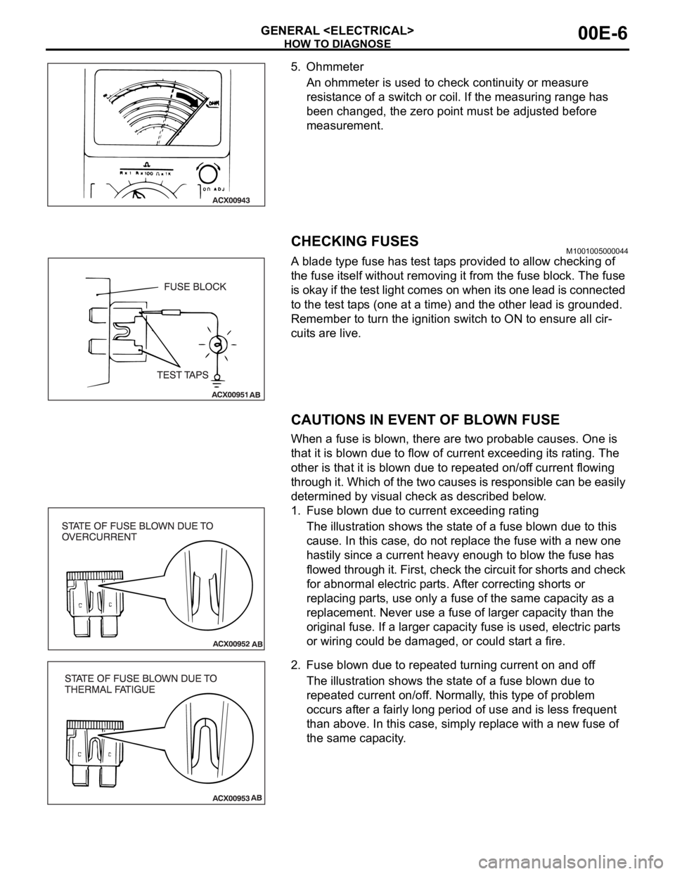
CHECKING FUSESM1001005000044
A blade type fuse has test taps provided to allow checking of
the fuse itself without removing it from the fuse block. The fuse
is okay if the test light comes on when its one lead is connected
to the test taps (one at a time) and the other lead is grounded.
Remember to turn the ignition switch to ON to ensure all cir-
cuits are live.
CAUTIONS IN EVENT OF BLOWN FUSE
When a fuse is blown, there are two probable causes. One is
that it is blown due to flow of current exceeding its rating. The
other is that it is blown due to repeated on/off current flowing
through it. Which of the two causes is responsible can be easily
determined by visual check as described below.
1. Fuse blown due to current exceeding rating
The illustration shows the state of a fuse blown due to this
cause. In this case, do not replace the fuse with a new one
hastily since a current heavy enough to blow the fuse has
flowed through it. First, check the circuit for shorts and check
for abnormal electric parts. After correcting shorts or
replacing parts, use only a fuse of the same capacity as a
replacement. Never use a fuse of larger capacity than the
original fuse. If a larger capacity fuse is used, electric parts
or wiring could be damaged, or could start a fire.
2. Fuse blown due to repeated turning current on and off
The illustration shows the state of a fuse blown due to
repeated current on/off. Normally, this type of problem
occurs after a fairly long period of use and is less frequent
than above. In this case, simply replace with a new fuse of
the same capacity.