heating MITSUBISHI 380 2005 Workshop Manual
[x] Cancel search | Manufacturer: MITSUBISHI, Model Year: 2005, Model line: 380, Model: MITSUBISHI 380 2005Pages: 1500, PDF Size: 47.87 MB
Page 918 of 1500

ENGINE COOLING DIAGNOSIS
ENGINE COOLING14-3
SYMPTOM CHARTM1141005600393
SYMPTOM PROCEDURES
INSPECTION PROCEDURE 1: Coolant Leak
DIAGNOSIS
STEP 1. Check for coolant leaks.
When pressure testing the cooling system, slowly
release cooling system pressure to avoid being
burned by hot coolant.
Be sure to completely clean away any moisture from
the places checked.
When the tester is removed, be careful not to spill any
coolant.
When installing and removing the tester and when test-
ing, be careful not to deform the filler neck of the radia-
tor.
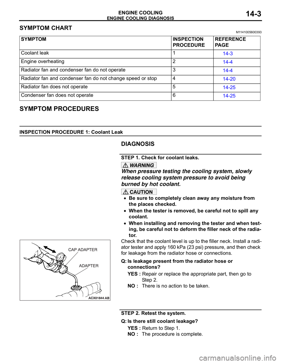
Check that the coolant level is up to the filler neck. Install a radi-
ator tester and apply 160 kPa (23 psi) pressure, and then check
for leakage from the radiator hose or connections.
Q: Is leakage present from the radiator hose or
connections?
YES : Repair or replace the appropriate part, then go to
St e p 2 .
NO : There is no action to be taken.
STEP 2. Retest the system.
Q: Is there still coolant leakage?
YES : Return to Step 1.
NO : The procedure is complete. SYMPTOM INSPECTION
PROCEDUREREFERENCE
PA G E
Coolant leak 1
14-3
Engine overheating 2
14-4
Radiator fan and condenser fan do not operate 3
14-4
Radiator fan and condenser fan do not change speed or stop 4
14-20
Radiator fan does not operate 5
14-25
Condenser fan does not operate 6
14-25
Page 919 of 1500

ENGINE COOLING DIAGNOSIS
ENGINE COOLING14-4
INSPECTION PROCEDURE 2: Engine Overheating
DIAGNOSIS
STEP 1. Remove the radiator cap and check for coolant
contamination.
Q: Is the coolant contaminated with rust and oil?
YES : Replace it. Refer to P.14-27.
NO : There is no action to be taken. Go to Step 2.
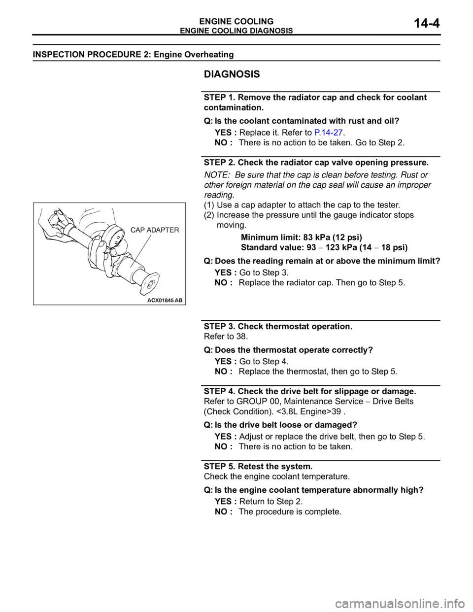
STEP 2. Check the radiator cap valve opening pressure.
NOTE: Be sure that the cap is clean before testing. Rust or
other foreign material on the cap seal will cause an improper
reading.
(1) Use a cap adapter to attach the cap to the tester.
(2) Increase the pressure until the gauge indicator stops
moving.
Minimum limit: 83 kPa (12 psi)
Standard value: 93
123 kPa (14 18 psi)
Q: Does the reading remain at or above the minimum limit?
YES : Go to Step 3.
NO : Replace the radiator cap. Then go to Step 5.
STEP 3. Check thermostat operation.
Refer to 38.
Q: Does the thermostat operate correctly?
YES : Go to Step 4.
NO : Replace the thermostat, then go to Step 5.
STEP 4. Check the drive belt for slippage or damage.
Refer to GROUP 00, Maintenance Service
Drive Belts
(Check Condition). <3.8L Engine>39 .
Q: Is the drive belt loose or damaged?
YES : Adjust or replace the drive belt, then go to Step 5.
NO : There is no action to be taken.
STEP 5. Retest the system.
Check the engine coolant temperature.
Q: Is the engine coolant temperature abnormally high?
YES : Return to Step 2.
NO : The procedure is complete.
Page 985 of 1500

CHARGING SYSTEM
ENGINE ELECTRICAL16-8
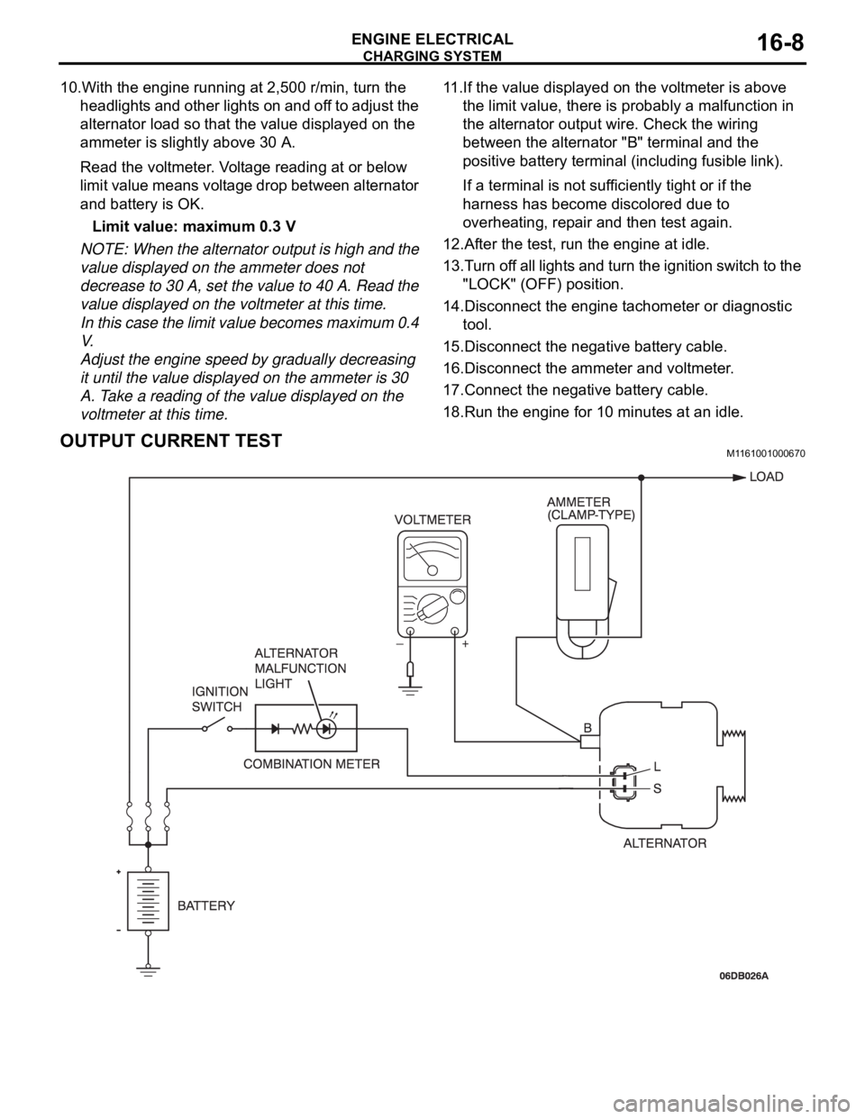
10.With the engine running at 2,500 r/min, turn the
headlights and other lights on and off to adjust the
alternator load so that the value displayed on the
ammeter is slightly above 30 A.
Read the voltmeter. Voltage reading at or below
limit value means voltage drop between alternator
and battery is OK.
Limit value: maximum 0.3 V
NOTE: When the alternator output is high and the
value displayed on the ammeter does not
decrease to 30 A, set the value to 40 A. Read the
value displayed on the voltmeter at this time.
In this case the limit value becomes maximum 0.4
V.
Adjust the engine speed by gradually decreasing
it until the value displayed on the ammeter is 30
A. Take a reading of the value displayed on the
voltmeter at this time.11.If the value displayed on the voltmeter is above
the limit value, there is probably a malfunction in
the alternator output wire. Check the wiring
between the alternator "B" terminal and the
positive battery terminal (including fusible link).
If a terminal is not sufficiently tight or if the
harness has become discolored due to
overheating, repair and then test again.
12.After the test, run the engine at idle.
13.Turn off all lights and turn the ignition switch to the
"LOCK" (OFF) position.
14.Disconnect the engine tachometer or diagnostic
tool.
15.Disconnect the negative battery cable.
16.Disconnect the ammeter and voltmeter.
17.Connect the negative battery cable.
18.Run the engine for 10 minutes at an idle.
OUTPUT CURRENT TESTM1161001000670
Page 1185 of 1500

ON-VEHICLE SERVICE
BASIC BRAKE SYSTEM35A-20
.
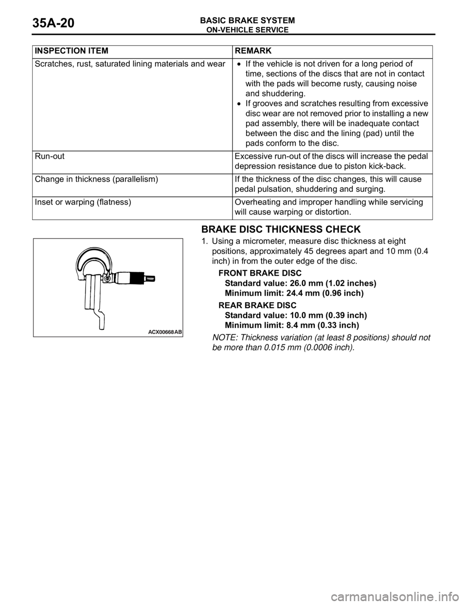
BRAKE DISC THICKNESS CHECK
1. Using a micrometer, measure disc thickness at eight
positions, approximately 45 degrees apart and 10 mm (0.4
inch) in from the outer edge of the disc.
FRONT BRAKE DISC
Standard value: 26.0 mm (1.02 inches)
Minimum limit: 24.4 mm (0.96 inch)
REAR BRAKE DISC
Standard value: 10.0 mm (0.39 inch)
Minimum limit: 8.4 mm (0.33 inch)
NOTE: Thickness variation (at least 8 positions) should not
be more than 0.015 mm (0.0006 inch). INSPECTION ITEM REMARK
Scratches, rust, saturated lining materials and wear
If the vehicle is not driven for a long period of
time, sections of the discs that are not in contact
with the pads will become rusty, causing noise
and shuddering.
If grooves and scratches resulting from excessive
disc wear are not removed prior to installing a new
pad assembly, there will be inadequate contact
between the disc and the lining (pad) until the
pads conform to the disc.
Run-out Excessive run-out of the discs will increase the pedal
depression resistance due to piston kick-back.
Change in thickness (parallelism) If the thickness of the disc changes, this will cause
pedal pulsation, shuddering and surging.
Inset or warping (flatness) Overheating and improper handling while servicing
will cause warping or distortion.