key battery MITSUBISHI 380 2005 Workshop Manual
[x] Cancel search | Manufacturer: MITSUBISHI, Model Year: 2005, Model line: 380, Model: MITSUBISHI 380 2005Pages: 1500, PDF Size: 47.87 MB
Page 5 of 1500

GENERAL DESCRIPTION
SIMPLIFIED WIRING SYSTEM (SWS)54B-5
INTERMITTENT CONTROL
ETACS-ECU uses the dial position of the variable
intermittent wiper control switch and the vehicle
speed signal sent by the combination meter to calcu-
late the interval to be sent to the front-ECU. The
front-ECU determines the intermittent time from the
input SWS data signal, and turns ON the windshield
wiper drive signal. When the wiper is at the STOP
position, the windshield wiper auto-stop signal goes
OFF to turn OFF the windshield wiper drive signal.
After the intermittent time from when the windshield
wiper drive signal turned ON, the windshield wiper
drive signal is turned ON again and the above opera-
tion is repeated.
.
MIST WIPER CONTROL
When the ignition switch is in the ACC or ON posi-
tion, and the windshield mist wiper switch of the col-
umn switch is turned ON, the front-ECU turns ON the
windshield wiper drive signal. At the same time, the
wiper speed switching relay is turned ON
(HIGH-SPEED). While the windshield mist wiper
switch is ON, the windshield wiper will operate at
high speed. Then, if the windshield mist wiper switch
is turned off, the wiper operates at low speed until it
stops at the predetermined park position.
When the windshield mist switch is turned on briefly,
the wiper operates once at low speed.
At the point the windshield mist switch is turned ON,
if the windshield wiper has been operating intermit-
tently, the same operations as the above will be per-
formed while the windshield mist wiper switch is ON.
After the windshield mist wiper switch goes OFF, the
intermittent operations will be set again after the
windshield wiper auto-stop signal last is turned ON.
.
WASHER CONTROL
When the ignition switch is in the ACC or ON posi-
tion, and the windshield washer switch of the column
switch is turned ON, the front-ECU turns ON the
windshield washer relay. The windshield wiper drive
signal is turned ON in 0.15 seconds until 2 seconds
after the windshield washer switch goes OFF to
operate the windshield wiper continuously. When the
windshield washer switch is turned ON, if the wind-
shield wiper is operating intermittently, intermittent
operations will be continued after continuous opera-
tions.
HEADLAMP
.
HEADLAMP AUTOMATIC SHUTDOWN
FUNCTION
Even if the lighting switch (tail lamp switch or
headlamp switch) is ON, the headlamps and tail
lamps will automatically go off in the following condi-
tions to prevent the battery from discharging:
When the ignition key is turned from "ON" to "LOCK"
(OFF) or "ACC" position with the lighting switch
turned ON, and this state continues for three min-
utes, the lamp will automatically be turned off. If the
driver's seat door is opened during these three min-
utes, the lamp will go off one second later.
.
HIGH-BEAM INDICATOR
At the same time that the high beams are illumi-
nated, the ETACS-ECU sends a signal to illuminate
the high-beam indicator via the CAN bus line. The
combination meter receives the transmitted signal
and turns the high-beam indicator on and off.
FLASHER TIMER
.
TURN-SIGNAL LAMP
The turn-signal lamp output (flashing signal) is
turned ON when the ignition switch is ON and the
turn-signal lamp switch is ON (LH or RH). If the front
turn-signal lamp or rear turn-signal lamp bulb has
burned out, the flashing speed increases to indicate
that the bulb has burned out.
.
HAZARD WARNING LAMP
Detects the signal where the hazard warning lamp
switch input changes from OFF to ON, and reverse
the flashing state according to this signal. The haz-
ard warning lamps toggle on and off whenever the
hazard warning lamp switch is operated.
.
TURN-SIGNAL INDICATORS
At the same time that the turn-signal lamps are illu-
minated, the ETACS-ECU sends a signal to illumi-
nate the turn-signal lamp indicator via the CAN bus
line. The combination meter receives the transmitted
signal and turns the turn-signal lamp indicator on and
off.
Page 6 of 1500

GENERAL DESCRIPTION
SIMPLIFIED WIRING SYSTEM (SWS)54B-6
FOG LAMP
.
FOG LAMP
The fog lamps will illuminate only when the fog lamp
switch is operated while the low-beam headlamps
are on.
The fog lamps will be switched off when any of the
following conditions is met. The fog lamps will also
be switched off automatically by headlamp automatic
shutdown function.
When the high-beam headlamps are switched
on, the fog lamps will be switched off. If the
low-beam headlamps are switched on again, the
fog lamps will illuminate again.
When the headlamp switch is turned off while the
tail lamps are on or the tail lamps and headlamps
are off, the fog lamps will be switched off. If the
low-beam headlamps are switched on again, the
fog lamps will not illuminate again.
.
FOG LAMP INDICATOR
At the same time that the fog lamps are illuminated,
the ETACS-ECU sends a signal to illuminate the fog
lamp indicator via the CAN bus line. The combination
meter receives the transmitted signal and turns the
fog lamp indicator on and off.
INTERIOR LAMP
ETACS-ECU makes it possible to force operation of
all ON and OFF lamp switches in the overhead con-
sole (the dome lamp, reading lamp, cargo area lamp,
rear personal lamps, front door lamps, and front foot
lamps). This function is assigned higher priority than
the controls for the interior lamp switch that are per-
formed when the doors are in certain positions.
When the lamps are forced on, the illumination
level is 100% as all interior lamps are switched on
(the dome lamp, reading lamp, cargo area lamp,
rear personal lamps, front door lamps, and front
foot lamps). Even when all lamps are forced on,
the interior lamp automatic shutoff function is
active.
When the lamps are forced off, all interior lamps
are immediately switched off (the dome lamp,
reading lamp, cargo area lamp, rear personal
lamps, front door lamps, and front foot lamps).When the interior lamp switch is at DOOR position,
the ETACS-ECU controls the interior lamps as fol-
lows:
When a door is opened with the ignition switch
off, the interior lamps up to a luminance of 100
percent. When a door is closed, the interior lamps
dims a luminance of 65 percent, and goes off 30
seconds later. However, if the ignition switch is
turned ON or if a door is locked while the interior
lamps is dimming, the dome lamp will go off at
that point.
When a door is opened with the ignition switch
ON, the interior lamps up at a luminance of 100
percent. When all doors are closed, the interior
lamps go off.
When the ignition key is removed with all doors
closed, the interior lamps up at a luminance of
100 percent, and goes off 30 seconds later. How-
ever, if the ignition key is inserted again or if a
door is locked while the interior lamps is lighting,
the interior lamps will go off at that point.
To check keyless entry operations more easily,
the interior lamps will flash twice when doors are
locked. When doors are unlocked, the interior
lamps up at a luminance of 100 percent, and
goes off 15 seconds later.
INTERIOR LAMP AUTOMATIC
SHUTDOUN FUNCTION
Illuminated interior lamps such as the front dome
lamp, etc. (all lamps using the dome lamp fuse as the
power supply) will automatically go off in the follow-
ing conditions to prevent the battery from discharging
as a result of forgetting to turn off the lamps or
incomplete closing of the door.
When the ignition switch is turned off and more
than 30 minutes pass by with the interior lamp
illuminated, the interior lamps will go off automati-
cally.
When the ignition switch is turned off and one of
the door switches remains open for 30 minutes
continuously, the interior lamps will go off auto-
matically.
Page 259 of 1500
SYMPTOM PROCEDURES
SIMPLIFIED WIRING SYSTEM (SWS)54B-259
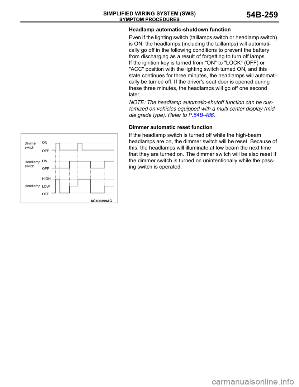
Headlamp automatic-shutdown function
Even if the lighting switch (taillamps switch or headlamp switch)
is ON, the headlamps (including the taillamps) will automati-
cally go off in the following conditions to prevent the battery
from discharging as a result of forgetting to turn off lamps.
If the ignition key is turned from "ON" to "LOCK" (OFF) or
"ACC" position with the lighting switch turned ON, and this
state continues for three minutes, the headlamps will automati-
cally be turned off. If the driver's seat door is opened during
these three minutes, the headlamps will go off one second
later.
NOTE: The headlamp automatic-shutoff function can be cus-
tomized on vehicles equipped with a multi center display (mid-
dle grade type). Refer to P.54B-486.
Dimmer automatic reset function
If the headlamp switch is turned off while the high-beam
headlamps are on, the dimmer switch will be reset. Because of
this, the headlamps will illuminate at low beam the next time
that they are turned on. The dimmer switch will be also reset if
the dimmer switch is turned on unintentionally while the pass-
ing switch is operated.
Page 356 of 1500
SYMPTOM PROCEDURES
SIMPLIFIED WIRING SYSTEM (SWS)54B-356
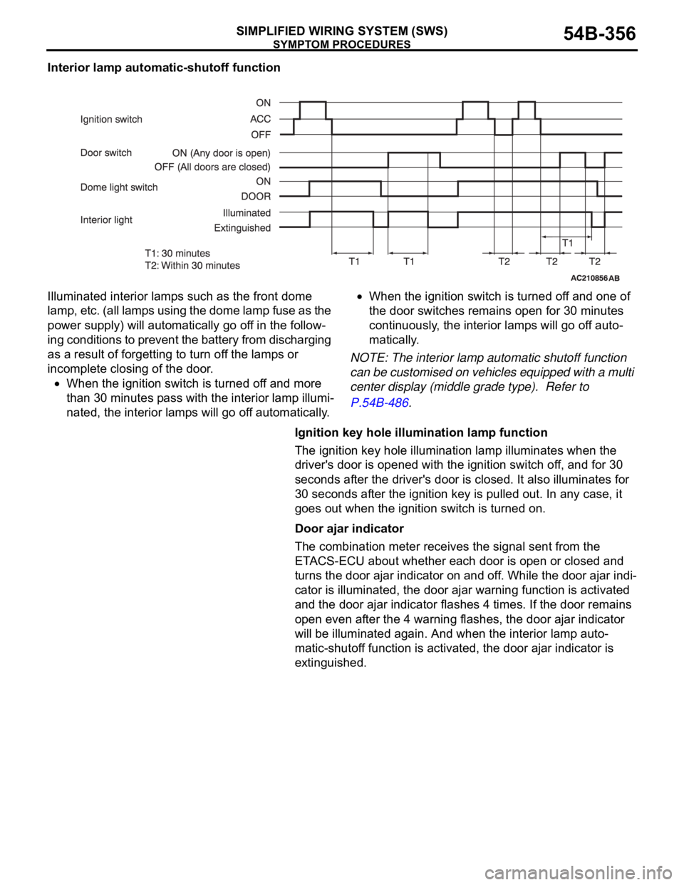
Interior lamp automatic-shutoff function
Illuminated interior lamps such as the front dome
lamp, etc. (all lamps using the dome lamp fuse as the
power supply) will automatically go off in the follow-
ing conditions to prevent the battery from discharging
as a result of forgetting to turn off the lamps or
incomplete closing of the door.
When the ignition switch is turned off and more
than 30 minutes pass with the interior lamp illumi-
nated, the interior lamps will go off automatically.
When the ignition switch is turned off and one of
the door switches remains open for 30 minutes
continuously, the interior lamps will go off auto-
matically.
NOTE: The interior lamp automatic shutoff function
can be customised on vehicles equipped with a multi
center display (middle grade type). Refer to
P.54B-486.
Ignition key hole illumination lamp function
The ignition key hole illumination lamp illuminates when the
driver's door is opened with the ignition switch off, and for 30
seconds after the driver's door is closed. It also illuminates for
30 seconds after the ignition key is pulled out. In any case, it
goes out when the ignition switch is turned on.
Door ajar indicator
The combination meter receives the signal sent from the
ETACS-ECU about whether each door is open or closed and
turns the door ajar indicator on and off. While the door ajar indi-
cator is illuminated, the door ajar warning function is activated
and the door ajar indicator flashes 4 times. If the door remains
open even after the 4 warning flashes, the door ajar indicator
will be illuminated again. And when the interior lamp auto-
matic-shutoff function is activated, the door ajar indicator is
extinguished.
Page 387 of 1500
SYMPTOM PROCEDURES
SIMPLIFIED WIRING SYSTEM (SWS)54B-387
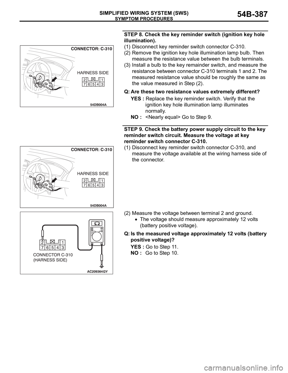
STEP 8. Check the key reminder switch (ignition key hole
illumination).
(1) Disconnect key reminder switch connector C-310.
(2) Remove the ignition key hole illumination lamp bulb. Then
measure the resistance value between the bulb terminals.
(3) Install a bulb to the key remainder switch, and measure the
resistance between connector C-310 terminals 1 and 2. The
measured resistance value should be roughly the same as
the value measured in Step (2).
Q: Are these two resistance values extremely different?
YES : Replace the key reminder switch. Verify that the
ignition key hole illumination lamp illuminates
normally.
NO :
STEP 9. Check the battery power supply circuit to the key
reminder switch circuit. Measure the voltage at key
reminder switch connector C-310.
(1) Disconnect key reminder switch connector C-310, and
measure the voltage available at the wiring harness side of
the connector.
(2) Measure the voltage between terminal 2 and ground.
The voltage should measure approximately 12 volts
(battery positive voltage).
Q: Is the measured voltage approximately 12 volts (battery
positive voltage)?
YES : Go to Step 11.
NO : Go to Step 10.
Page 388 of 1500
SYMPTOM PROCEDURES
SIMPLIFIED WIRING SYSTEM (SWS)54B-388
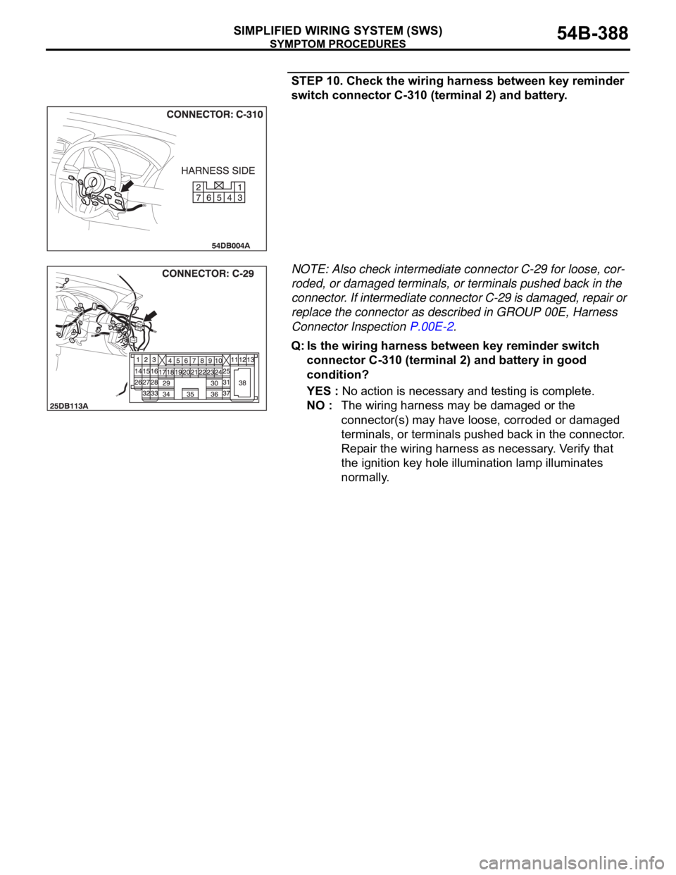
STEP 10. Check the wiring harness between key reminder
switch connector C-310 (terminal 2) and battery.
NOTE: Also check intermediate connector C-29 for loose, cor-
roded, or damaged terminals, or terminals pushed back in the
connector. If intermediate connector C-29 is damaged, repair or
replace the connector as described in GROUP 00E, Harness
Connector Inspection P.00E-2.
Q: Is the wiring harness between key reminder switch
connector C-310 (terminal 2) and battery in good
condition?
YES : No action is necessary and testing is complete.
NO : The wiring harness may be damaged or the
connector(s) may have loose, corroded or damaged
terminals, or terminals pushed back in the connector.
Repair the wiring harness as necessary. Verify that
the ignition key hole illumination lamp illuminates
normally.
Page 408 of 1500

INPUT SIGNAL PROCEDURES
SIMPLIFIED WIRING SYSTEM (SWS)54B-408
INSPECTION PROCEDURE M-2: ETACS-ECU does not receive any signal from the ignition switch
(IG1).
.
CIRCUIT OPERATION
The ETACS-ECU operates the following equipment
or functions according to signal from the ignition
switch (IG1):
Light reminder tone alarm function
Seat belt tone alarm function
Door ajar warning buzzer
Turn-signal lamp buzzer
Multi center display operation tone
Power window timer function
Sunroof timer function
Headlamp automatic shutdown function
Turn-signal lamp
Dome lamp dimming function
Ignition key hole illumination lamp
If the power supply circuit from the battery to the
ETACS-ECU is open, this circuit is used as
backup circuit.
If the signal is not normal, the equipment or functions
described in "CIRCUIT OPERATION" do not work
normally.
The ETACS-ECU receives information on the ignition
switch condition (IG1) from the combination meter
via CAN communication. If the ignition switch (IG1)
input signal is incorrect, refer to the Diagnostic Trou-
ble Code Chart P.54B-25.
.
TROUBLESHOOTING HINTS
Refer to circuit diagrams GROUP-90
Refer to configuration diagrams GROUP-80
The wiring harness or connectors may have
loose, corroded, or damaged terminals, or termi-
nals pushed back in the connector
The ETACS-ECU may be defective
DIAGNOSIS
Required Special Tool:
MB991223: Harness Set
STEP 1. Check ETACS-ECU connector C-219 for loose,
corroded or damaged terminals, or terminals pushed back
in the connector.
Q: Is ETACS-ECU connector C-219 in good condition?
YES : Go to Step 2.
NO : Repair or replace the damaged component(s). Refer
to GROUP 00E, Harness Connector Inspection
P.00E-2. If the functions described in "CIRCUIT
OPERATION" work normally, the input signal from the
ignition switch (IG1) should be normal.
Page 472 of 1500
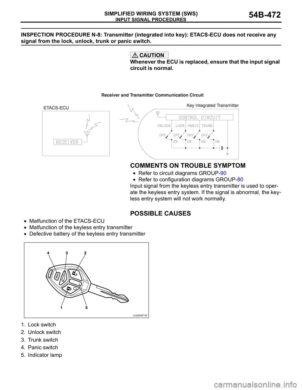
INPUT SIGNAL PROCEDURES
SIMPLIFIED WIRING SYSTEM (SWS)54B-472
INSPECTION PROCEDURE N-8: Transmitter (integrated into key): ETACS-ECU does not receive any
signal from the lock, unlock, trunk or panic switch.
Whenever the ECU is replaced, ensure that the input signal
circuit is normal.
.
COMMENTS ON TROUBLE SYMPTOM
Refer to circuit diagrams GROUP-90
Refer to configuration diagrams GROUP-80
Input signal from the keyless entry transmitter is used to oper-
ate the keyless entry system. If the signal is abnormal, the key-
less entry system will not work normally.
.
POSSIBLE CAUSES
Malfunction of the ETACS-ECU
Malfunction of the keyless entry transmitter
Defective battery of the keyless entry transmitter
1. Lock switch
2. Unlock switch
3. Trunk switch
4. Panic switch
5. Indicator lamp
Page 473 of 1500

INPUT SIGNAL PROCEDURES
SIMPLIFIED WIRING SYSTEM (SWS)54B-473
DIAGNOSTIC PROCEDURE
Step 1. Pulse check
Check whether the ETACS-ECU receives signal from a trans-
mitter or not. For this check, you should use the 4-button-type
transmitter (integrated with a key), which has already been reg-
istered.
NOTE: For how to register the keyless entry transmitter
encrypted code, refer to GROUP 42
On-vehicle Service
P.42-73.
OK: The MUT-III sounds or the voltmeter needle fluctu-
ates.
Q: Is the check result normal?
YES : Go to Step 2.
NO : Go to Step 4.
Step 2. Check the transmitter battery.
Refer to GROUP 42
Keyless entry system P.42-70.
Q: Is the check result normal?
YES : Go to Step 3.
NO : Replace the keyless entry key integrated transmitter
battery.
Step 3. Register the encrypted code, and then retest the
system.
(1) Register the keyless entry transmitter again.
(2) Check that each signal is received from the keyless entry
transmitter.
Q: Is the check result normal?
YES : The trouble can be an intermittent malfunction (Refer
to GROUP 00
How to Cope with Intermittent
Malfunction P.00-14).
NO : Replace the keyless entry transmitter.
Step 4. Retest the system.
Check that each signal is received from the keyless entry key
integrated transmitter.
Q: Is the check result normal?
YES : The trouble can be an intermittent malfunction (Refer
to GROUP 00
How to Cope with Intermittent
Malfunction P.00-14).
NO : Replace the ETACS-ECU. System switch Check condition
Keyless entry transmitter
"LOCK/UNLOCK" switchWhen the switch is
turned from off to on
Keyless entry transmitter
"Panic" switchWhen the switch is
turned from off to on
Keyless entry transmitter
"Trunk" switchWhen the switch is
turned from off to on
Page 481 of 1500

CHECK AT ECU TERMINAL
SIMPLIFIED WIRING SYSTEM (SWS)54B-481
22 Output to door unlock (for
driver's door)When driver's door lock actuator
is operating (doors unlocked)Battery positive voltage
23, 24
25 Input of door lock key cylinder
switch (UNLOCK) signalDoor lock key cylinder switch:
UNLOCK0 V
26
28
29 Input of rear door lock actuator
(UNLOCK) signalRear door lock actuator:
UNLOCK0 V
30 Input of key reminder switch
signalKey reminder switch: ON (when
ignition key is removed)0 V
31, 32
33 Input of door lock switch (LOCK)
signalDoor lock switch (incorporated in
power window switch): LOCK0 V
34 Input of door lock switch
(UNLOCK) signalDoor lock switch (incorporated in
power window switch): UNLOCK0 V
35 Input from rear door switch (RH) Rear door switch (RH): ON (rear
door (RH) open)0 V
36 Input of driver's door lock
actuator (UNLOCK) signalDriver's door lock actuator:
UNLOCK0 V
37 Input from trunk lid latch
assemblyTrunk lid latch: ON (trunk open) 0 V
38 Ground (for sensor) Always 0 V
39
41
42 Input of door lock key cylinder
switch (LOCK) signalDoor lock key cylinder switch:
LOCK0 V
43 Input of front passenger's door
lock actuator (UNLOCK) signalFront passenger’s door lock
actuator: UNLOCK0 V
44 Output to horn relay When a horn sounds by the
keyless entry horn answerback
function2 V or less
45 Output to data link connector When DTC sets 0
12 V (pulse signal)
When input check signal is
output0
12 V (when input
pulse signal is
fluctuating)
46 Output to trunk lamp When trunk lid latch on. 0 V
47
48 Input of fog lamp switch signal Fog lamp switch: ON 0 V
49 Input of hazard warning lamp
switch signalHazard warning lamp switch: ON
(When the switch is depressed)0 V
50 Ground (for sensor) Always 0 V
51 Key Ring Antenna (+) 0 V 0 V
52 Key Ring Antenna (-) 0 V 0 V
53 SWS communication line Always 0
12 V (pulse signal) TERMINAL
NO.INSPECTION ITEM INSPECTION CONDITION NORMAL VALUE