open hood MITSUBISHI 380 2005 Workshop Manual
[x] Cancel search | Manufacturer: MITSUBISHI, Model Year: 2005, Model line: 380, Model: MITSUBISHI 380 2005Pages: 1500, PDF Size: 47.87 MB
Page 984 of 1500

CHARGING SYSTEM
ENGINE ELECTRICAL16-7
ON-VEHICLE SERVICE
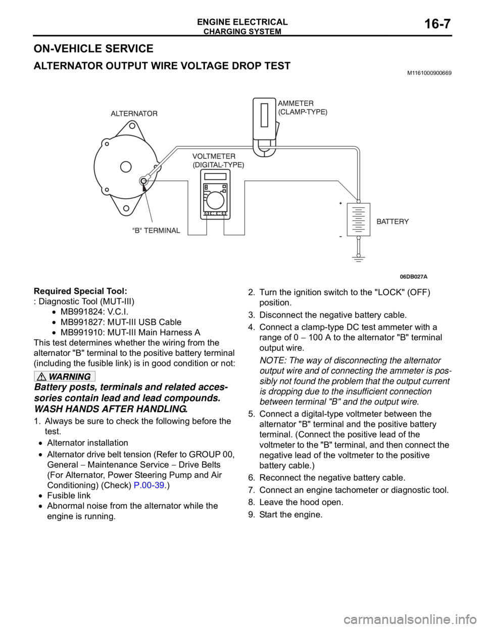
ALTERNATOR OUTPUT WIRE VOLTAGE DROP TESTM1161000900669
Required Special Tool:
: Diagnostic Tool (MUT-III)
MB991824: V.C.I.
MB991827: MUT-III USB Cable
MB991910: MUT-III Main Harness A
This test determines whether the wiring from the
alternator "B" terminal to the positive battery terminal
(including the fusible link) is in good condition or not:
Battery posts, terminals and related acces-
sories contain lead and lead compounds.
WASH HANDS AFTER HANDLING.
1. Always be sure to check the following before the
test.
Alternator installation
Alternator drive belt tension (Refer to GROUP 00,
General
Maintenance Service Drive Belts
(For Alternator, Power Steering Pump and Air
Conditioning) (Check) P.00-39.)
Fusible link
Abnormal noise from the alternator while the
engine is running.2. Turn the ignition switch to the "LOCK" (OFF)
position.
3. Disconnect the negative battery cable.
4. Connect a clamp-type DC test ammeter with a
range of 0
100 A to the alternator "B" terminal
output wire.
NOTE: The way of disconnecting the alternator
output wire and of connecting the ammeter is pos-
sibly not found the problem that the output current
is dropping due to the insufficient connection
between terminal "B" and the output wire.
5. Connect a digital-type voltmeter between the
alternator "B" terminal and the positive battery
terminal. (Connect the positive lead of the
voltmeter to the "B" terminal, and then connect the
negative lead of the voltmeter to the positive
battery cable.)
6. Reconnect the negative battery cable.
7. Connect an engine tachometer or diagnostic tool.
8. Leave the hood open.
9. Start the engine.
Page 986 of 1500

CHARGING SYSTEM
ENGINE ELECTRICAL16-9
Required Special Tool:
: Diagnostic Tool (MUT-III)
MB991824: V.C.I.
MB991827: MUT-III USB Cable
MB991910: MUT-III Main Harness A
This test determines whether the alternator outputs
normal current. For best results, use a charging sys-
tem tester. If not available, follow the steps below.
Battery posts, terminals and related acces-
sories contain lead and lead compounds.
WASH HANDS AFTER HANDLING.
1. Before the test, always be sure to check the
following.
Alternator installation
Battery (Refer to GROUP 54A, Chassis Electrical
Battery On-vehicle Service Battery Check
P.54A-5.)
NOTE: The battery to be used should be slightly
discharged. The load in a fully-charged battery
will be insufficient and the test may not be able to
be carried out correctly.
Alternator drive belt tension (Refer to GROUP 00,
General
Maintenance Service Drive Belts
(For Alternator, Power Steering Pump and Air
Conditioning) (Check) P.00-39.)
Fusible link
Abnormal noise from the alternator while the
engine is running.
2. Turn the ignition switch to the "LOCK" (OFF)
position.
3. Disconnect the negative battery cable.
Never use clips to connect the wire. Loose
connections (for example, using clips) will
lead to a serious accident because of high
current.
4. Connect a clamp-type DC test ammeter with a
range of 0
120 A to the alternator "B" terminal
output wire.
5. Connect a voltmeter with a range of 0
20 V
between the alternator "B" terminal and ground.
(Connect the positive lead of the voltmeter to the
"B" terminal, and then connect the negative lead
of the voltmeter to ground.)
6. Connect the negative battery cable.
7. Connect an engine tachometer or diagnostic tool.
8. Leave the hood open.9. Check to be sure that the reading on the voltmeter
is equal to the battery positive voltage.
NOTE: If the voltage is 0 V, the cause is probably
an open circuit in the wire or fusible link between
the alternator "B" terminal and the battery positive
terminal or malfunctioning voltmeter.
10.After turning on the headlights, start the engine.
NOTE: Because the current from the battery will
soon drop after the engine is started, step 11
should be carried out as quickly as possible in
order to obtain the maximum current output value.
11.Immediately after setting the headlights to high
beam and turning the heater blower switch to the
highest position, increase the engine speed to
2,500 r/min and read the maximum current output
value displayed on the ammeter.
Limit value: 70 % of nominal current output
NOTE: For the nominal current output, refer to the
Alternator Specifications.
NOTE: The current output value will depend on
the electrical load and the temperature of the
alternator body.
NOTE: If the electrical load is small while testing,
the specified level of current may not be output
even though the alternator is normal. In such
cases, increase the electrical load by leaving the
headlights turned on for some time to discharge
the battery or by using the lighting system in
another vehicle, and then test again.
NOTE: The specified level of current also may not
be output if the temperature of the alternator body
or the ambient temperature is too high. In such
cases, cool the alternator and then test again.
12.The reading on the ammeter should be above the
limit value. If the reading is below the limit value
and the alternator output wire is normal, remove
the alternator from the engine and check the
alternator.
13.Run the engine at idle speed after the test.
14.Turn the ignition switch to the "LOCK" (OFF)
position.
15.Disconnect the engine tachometer or diagnostic
tool.
16.Disconnect the negative battery cable.
17.Disconnect the ammeter and voltmeter .
18.Connect the negative battery cable.
19.Run the engine for 10 minutes at an idle.
Page 1040 of 1500

GARNISHES AND MOLDINGS
EXTERIOR51-7
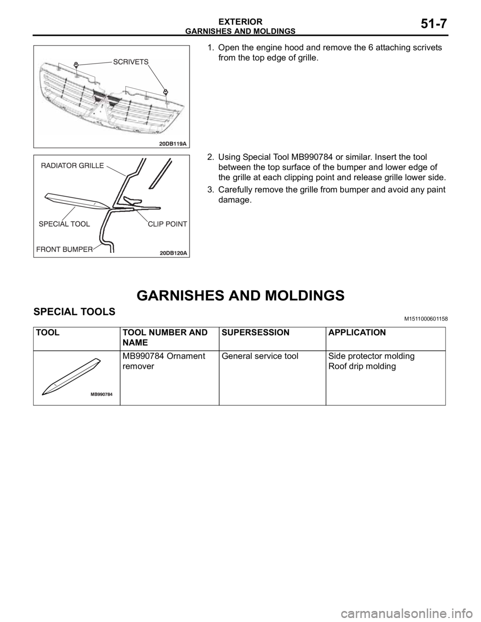
1. Open the engine hood and remove the 6 attaching scrivets
from the top edge of grille.
2. Using Special Tool MB990784 or similar. Insert the tool
between the top surface of the bumper and lower edge of
the grille at each clipping point and release grille lower side.
3. Carefully remove the grille from bumper and avoid any paint
damage.
GARNISHES AND MOLDINGS
SPECIAL TOOLSM1511000601158
TOOL TOOL NUMBER AND
NAMESUPERSESSION APPLICATION
MB990784 Ornament
removerGeneral service tool Side protector molding
Roof drip molding