heating MITSUBISHI ASX 2012 (in English) User Guide
[x] Cancel search | Manufacturer: MITSUBISHI, Model Year: 2012, Model line: ASX, Model: MITSUBISHI ASX 2012Pages: 378, PDF Size: 18.2 MB
Page 197 of 378
CAUTION
l
For safety reasons, the “ASC OFF”
switch should be operated when your ve-
hicle is stopped.
l Be sure to keep the ASC on while driving
in normal circumstances.
NOTE l When
moving out of mud, sand or fresh
snow, pressing the accelerator pedal may not
allow the engine speed to increase. In such sit-
uations, temporarily turning off the ASC
with the “ASC OFF” switch will make it eas-
ier to move out your vehicle.
l Using the “ASC OFF” switch turns off both
the stability control function and the traction
control function.
l If you continue to press the “ASC OFF”
switch after the ASC is turned off, the “mis-
taken operation protection function” will ac-
tivate and the ASC will turn back on.
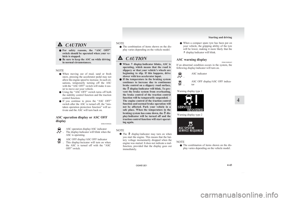
ASC operation display or ASC OFF
display E00619300426 -
ASC operation display/ASC indicator
The
display/indicator will blink when the
ASC is operating. -
ASC OFF display/ASC OFF indicator
This
display/incicator will turn on when
the ASC is turned off with the “ASC
OFF” switch. NOTE
l The
combination of items shown on the dis-
play varies depending on the vehicle model. CAUTION
l
When display/indicator blinks, ASC is
operating,
which means that the road is
slippery or that your vehicle’s wheels are
beginning to slip. If this happens, drive
slower with less accelerator input.
l If the temperature in the braking system
continues to increase due to continuous
brake control on a slippery road surface,
the display/indicator will blink. To pre-
vent
the brake system from overheating,
the brake control of the traction control
function will be temporarily suspended.
The engine control of the traction control
function and normal brake operation will
not be affected. Park your vehicle in a
safe place. When the temperature in the
braking system has come down, the dis-
play/indicator
will be turned off and the
traction control function will start operat-
ing again.
NOTE l The display/indicator may turn on when
you
start the engine. This means that the bat-
tery voltage momentarily dropped when the
engine was started. It does not indicate a mal-
function, provided that the display goes out
immediately. l
When
a compact spare tyre has been put on
your vehicle, the gripping ability of the tyre
will be lower, making it more likely that the display/indicator will blink.
ASC warning display E00619400443
If an abnormal condition occurs in the system, the
following display/indicator will turn on. -
ASC indicator -
ASC OFF display/ASC OFF indica-
tor
Warning display type 1 Warning display type 2
NOTE
l The
combination of items shown on the dis-
play varies depending on the vehicle model. Starting and driving
4-43 4
OGWE12E1
Page 211 of 378
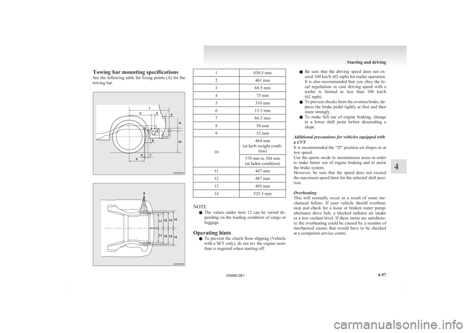
Towing bar mounting specifications
See
the following table for fixing points (A) for the
towing bar. 1
830.5 mm
2 461 mm
3 68.5 mm
4 75 mm
5 310 mm
6 13.5 mm
7 66.5 mm
8 50 mm
9 52 mm
10 464 mm
(at kerb weight condi- tion)
370 mm to 384 mm (at laden condition)
11 447 mm
12 487 mm
13 495 mm
14 525.5 mm NOTE
l The
values under item 12 can be varied de-
pending on the loading condition of cargo or
luggage.
Operating hints l To prevent the clutch from slipping (Vehicle
with a M/T only), do not rev the engine more
than is required when starting off. l
Be
sure that the driving speed does not ex-
ceed 100 km/h (62 mph) for trailer operation.
It is also recommended that you obey the lo-
cal regulations in case driving speed with a
trailer is limited to less than 100 km/h
(62 mph).
l To prevent shocks from the overrun brake, de-
press the brake pedal lightly at first and then
more strongly.
l To make full use of engine braking, change
to a lower shift point before descending a
slope.
Additional precautions for vehicles equipped with
a CVT
It is recommended the “D” position on slopes or at
low speed.
Use the sports mode in mountainous areas in order
to make better use of engine braking and to assist
the brake system.
However, be sure that the speed does not exceed
the maximum speed limit for the selected shift posi-
tion.
Overheating
This will normally occur as a result of some me-
chanical failure. If your vehicle should overheat,
stop and check for a loose or broken water pump/
alternator drive belt, a blocked radiator air intake
or a low coolant level. If these items are satisfacto-
ry the overheating could be caused by a number of
mechanical causes that would have to be checked
at a competent service centre. Starting and driving
4-57 4
OGWE12E1
Page 212 of 378

CAUTION
l
If the engine overheats, please refer to the
“Engine
overheating” section of “For
emergencies” prior to taking any correc-
tive action.
l On vehicles equipped with CVT, if the warning display is showing, the tempera-
ture of the CVT fluid is high.
Read
the reference page and take the re-
quired measures.
Refer to “When a malfunction occurs in
the CVT” on page 4-28. Starting and driving
4-58
4
OGWE12E1
Page 216 of 378

Temperature control dial
E00700900368
Turn the temperature control dial clockwise or anti-
clockwise.Heater/
Manual air conditioning Automatic air conditioningNOTE
l While
the engine coolant temperature is low,
the temperature of the air from the heater
will be cool/cold until the engine warms up,
even if you have selected warm air with the
dial.
l On vehicles with the automatic air condition-
ing, when the temperature is set to the high-
est or the lowest setting under the AUTO op-
eration, the air selection and the air condition-
ing will be automatically changed as follows.
• Quick Heating (When the temperature isset to the highest setting)
Outside air will be introduced and the air
conditioning will stop.
• Quick Cooling (When the temperature is set to the lowest setting)
Inside air will be recirculated and the air
conditioning will operate. The settings described above are the factory set-
tings.
The air selection and air conditioning
switches can be customized (function setting
changed), and the automatic switching of outside
air and the air conditioning according to operating
conditions can be changed as desired.
For further information, we recommend you to con-
sult a MITSUBISHI MOTORS Authorized Service
Point.
Refer to “Customizing the air conditioning switch
(Automatic air conditioning)” on page 5-05.
Refer to “Customizing the air selection” on page
5-05.
Air selection switch E00701300721
To change the air selection, simply press the air se-
lection
switch. There is a sound each time the
switch is pressed.
l Outside air: Indication lamp (A) is OFF
Outside air is introduced into the passenger
compartment.
l Recirculated air: Indication lamp (A) is ON
Air is recirculated inside the passenger com-
partment.
Heater/
Manual air conditioning Automatic air conditioning CAUTION
l
Normally, use the outside position to keep
the
windscreen and side windows clear
and quickly remove fog or frost from the
windscreen.
If high cooling performance is desired, or
if the outside air is dusty or otherwise con-
taminated use the recirculation position.
Switch to the outside position periodically
to increase ventilation so that the win-
dows do not become fogged up.
l Use of the recirculation position for exten-
ded time may cause the windows to fog up.
NOTE l On
vehicles with the heater and the manual
air conditioning, when the system operates
with the selection switch in the outside posi-
tion, the system automatically determines
whether to continue using outside air or to
perform recirculation. If the outside air tem-
perature is high, the system selects recircula-
tion and causes the indication lamp (A) in
the switch to illuminate (for vehicles with
the manual air conditioning, the system se-
lects recirculation to achieve rapid cooling).
Press the selection switch to return to outside
air introduction.
l On vehicles with the automatic air condition-
ing, when the mode selection dial or the blow-
er speed selection dial is set to the “AUTO”
position again after manual operation, the air
selection dial will also be automatically con-
trolled. For pleasant driving
5-04
5
OGWE12E1
Page 218 of 378

l
Enable automatic air conditioning control:
If the mode selection dial or blower speed se-
lection
dial is turned to the “AUTO” posi-
tion, or the temperature control dial is set to
the minimum temperature, the air condition-
ing switch is controlled automatically.
l Disable automatic air conditioning control:
The air conditioning switch is not controlled
automatically as long as the air conditioning
switch is not operated.
l Setting change method
Hold down the air conditioning switch for
about 10 seconds or more.
When the setting is changed, a sound is emit-
ted and the indication lamp flashes.
• When the setting is changed from enableto disable 3 sounds are emitted and the in-
dication lamp flashes 3 times.
• When the setting is changed from disable to enable 2 sounds are emitted and the in-
dication lamp flashes 3 times.
NOTE l The factory setting is “Enable automatic air
conditioning control”.
l When you turn the mode selection dial to
“ ”,
in order to prevent misting of the win-
dows the air conditioning operates automati-
cally even if “Disable automatic air condition-
ing control” is set.
Operating the air conditioning system E00701800436
Heating (Heater/Manual air conditioning)
Set
the mode selection dial to the “ ”
position
and set the air selection switch (A) to the outside po-
sition. Turn the temperature control dial clockwise or anti-
clockwise
to the desired temperature. Select the de-
sired blower speed. NOTE
l For
quick heating, set the blower speed selec-
tion dial to the position shown in the illustra-
tion. Cooling (Manual air conditioning)
E00701900684 1.
Set
the mode selection dial to the “ ” posi-
tion.
2. Set the air selection switch (A) to the outside position.
3. Push the air conditioning switch (B).
4. Change the temperature by turning the con- trol dial clockwise or anticlockwise.
5. Select the desired blower speed. CAUTION
l
If
the outside air is dusty or otherwise con-
taminated, or if high cooling performance
is desired, set air selection switch to the re-
circulation position and the temperature
control dial all the way to the left.
Switch to the outside position periodically
to increase ventilation so that the win-
dows do not become fogged up. For pleasant driving
5-06
5
OGWE12E1
Page 272 of 378
Ashtray*
E00711401009CAUTION
l
Put out matches and cigarettes before
they are placed in the ashtray.
l Don’t put papers and other things that
burn into your ashtrays. If you do, ciga-
rettes or other smoking materials could
set them on fire, causing damage.
l Always close the ashtray. If left open, oth-
er cigarette butts in the ashtray may be re-
kindled.
To use the ashtray, open the lid. Moveable ashtray secure holder
The
moveable ashtray can be fitted at the indicated
position. CAUTION
l
The
moveable ashtray secure holder
should never be used as a cup holder.
Drinks could be spilled over the cigarette
lighter by the vibration and jolts while
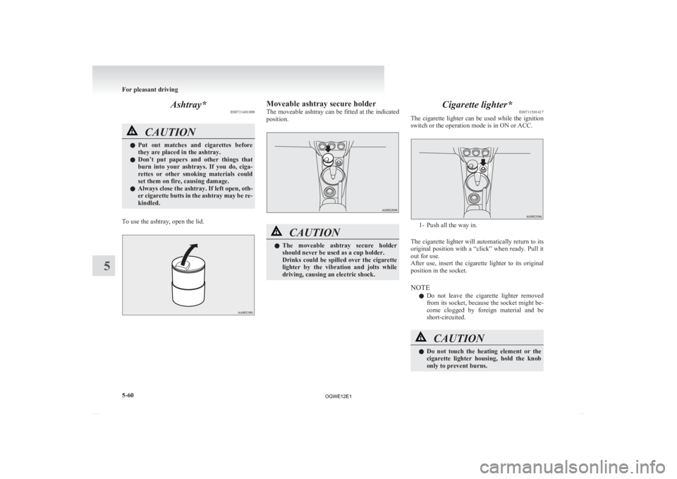
driving, causing an electric shock. Cigarette lighter*
E00711501417
The
cigarette lighter can be used while the ignition
switch or the operation mode is in ON or ACC. 1- Push all the way in.
The
cigarette lighter will automatically return to its
original position with a “click” when ready. Pull it
out for use.
After use, insert the cigarette lighter to its original
position in the socket.
NOTE
l Do not leave the cigarette lighter removed
from its socket, because the socket might be-
come clogged by foreign material and be
short-circuited. CAUTION
l
Do
not touch the heating element or the
cigarette lighter housing, hold the knob
only to prevent burns. For pleasant driving
5-60
5
OGWE12E1
Page 283 of 378

If the vehicle breaks down
............................................................ 6-02
Emergency starting ....................................................................... 6-02
Engine overheating ....................................................................... 6-04
Tools, jack and tyre repair kit ....................................................... 6-05
How to change a tyre .................................................................... 6-12
Towing.......................................................................................... 6-18
Operation under adverse driving conditions .................................6-22For emergencies
6
OGWE12E1
Page 285 of 378

Petrol-powered vehicles1600 models
1800 models, 2000 models Diesel-powered vehicles
7. Connect one end of the other jumper cable to
the negative (-) terminal of the booster bat-
tery, and the other end to the engine block of
the vehicle with the discharged battery at the
point farthest from the battery. WARNING
l Make
sure you observe the following or-
der when connecting the cables: l
Make sure you make connection to the
correct
designated location (as shown in
the illustration). If the connection is made
directly to the negative (-) side of the bat-
tery, flammable gases generated from the
battery might catch fire and explode.
l When connecting the jumper cables, do
not allow the positive (+) cable and nega-
tive (-) terminal to make contact. Other-
wise sparks might cause explosion of the
battery. CAUTION
l
Take
care not to get the jumper cable
caught in the cooling fan or other rotat-
ing part in the engine compartment.
l Use the proper cables suitable for the bat-
tery size to prevent overheating of the ca-
bles.
l Check the jumper cables for damage and
corrosion before use.
8. Start
the engine in the vehicle which has the booster battery, let the engine idle a few mi-
nutes, then start the engine in the vehicle
with the discharged battery. CAUTION
l
Keep
the engine of the vehicle giving assis-
tance running.
NOTE l For
vehicles equipped with the Auto Stop &
Go (AS&G) system, press the “Auto Stop &
Go (AS&G) OFF” switch to deactivate the
Auto Stop & Go (AS&G) system and pre-
vent the engine from automatically stopping
before the battery is sufficiently charged.
Refer to “To deactivate” on page 4-21.
9. After the engine is started, disconnect the ca- bles in the reverse order and keep the engine
running for several minutes. For emergencies
6-03 6
OGWE12E1
Page 286 of 378

WARNING
l If the battery has to be charged while fit-
ted in the vehicle, disconnect the vehicle
side negative (-) terminal connected to the
battery.
l Keep sparks, cigarettes and flames away
from the battery because the battery may
produce an explosion.
l Use adequate ventilation when charging
or using the battery in an enclosed space.
l Remove all the caps before charging the
battery.
l Electrolyte is corrosive diluted sulphuric
acid.
If electrolyte (battery acid) comes into con-
tact with your hands, eyes, clothes and
the painted surface of your vehicle, it
should be thoroughly flushed with water.
If electrolyte gets in your eyes, flush them
with water immediately and thoroughly,
and get prompt medical attention.
NOTE l If
the vehicle is put in motion without fully
charging the battery, it might cause the loss
of smooth engine operation and the anti-lock
brake warning lamp to illuminate.
Refer to “Anti-lock brake system (ABS)” on
page 4-39. Engine overheating
E00800602504
When
the engine is overheating, the information
screen in the multi-information display will be in-
terrupted and the engine coolant temperature warn-
ing display will appear. Also “ ” will blink.
If
this occurs, take the following corrective meas-
ures: 1. Stop the vehicle in a safe place.
2. Check whether steam is coming from the en-gine compartment.
[If steam does not come from the engine com-
partment]
With the engine still running, raise the bon-
net to ventilate the engine compartment.
NOTE l For vehicles equipped with the Auto Stop &
Go (AS&G) system, press the “Auto Stop &
Go (AS&G) OFF” switch to deactivate the
Auto Stop & Go (AS&G) system before stop-
ping the vehicle.
Refer to “To deactivate” on page 4-21.
[If steam is coming from the engine compart-
ment]
Stop the engine, and when the steam stops,
raise the bonnet to ventilate the engine com-
partment. Restart the engine. WARNING
l Do
not open the bonnet while steam is com-
ing from the engine compartment. It
could cause steam or hot water to spurt
out, causing burns. Hot water could spurt
out even when there is no steam coming
out, and some parts will be very hot. Be
very careful when opening the bonnet.
l Be careful of hot steam, which could
cause the cap on the engine reserve tank
to blow off.
l Do not attempt to remove the radiator
cap while the engine is hot.
3. Confirm
that the cooling fans (A) are turn- ing. If the fans are not turning, stop the en-
gine immediately and have it checked. *: Front of the vehicle
WARNING
l Be
careful not to get your hands or
clothes caught in the cooling fan. For emergencies
6-04
6
OGWE12E1
Page 292 of 378
CAUTION
l
Any sand or dust sucked into the compres-
sor could make the compressor break
down. Do not place the compressor direct-
ly on any sandy or dusty surface when us-
ing it.
l Do not disassemble or modify the com-
pressor. Also, do not subject the air pres-
sure gauge to shock. It could malfunction.
15. Check
and adjust the tyre pressure with refer- ence to the air pressure gauge on the compres-
sor. If you overinflate the tyre, release air by
loosening the hose’s end fitting. (Refer to
“Tyre inflation pressures” on page 8-12.)
If there is a gap between the tyre and wheel
because the tyre has moved inward from the
wheel rim, press the periphery of the tyre to-
wards the wheel to close the gap before run-
ning the compressor. (With no gaps, the tyre
pressure will rise.) CAUTION
l
Be
careful not to get your fingers trapped
between the tyre and wheel as the tyre in-
flates.
l The surface of the compressor will get
hot while the compressor is running. Do
not keep the compressor running continu-
ously for more than 10 minutes. After us-
ing the compressor, wait for the compres-
sor to cool before using it again. CAUTION
l
If
the compressor becomes sluggish or
hot while operating, it is overheating. Im-
mediately place the switch in the OFF po-
sition and let the compressor cool down
for at least 30 minutes.
NOTE l If
the tyre pressure does not rise to the speci-
fied level within 10 minutes, the tyre may be
so severely damaged that the tyre sealant can-
not be used to effect an emergency repair.
Please contact a MITSUBISHI MOTORS Au-
thorized Service Point or another specialist
in this event.
16. Turn OFF the compressor switch, then pull the power cord plug out of the socket.
NOTE l Simply putting sealant and air into the tyre us-
ing the tyre repair kit does not seal the punc-
ture hole. Air will leak through the puncture
hole until the emergency repair procedure is
completed (through step 19 of these instruc-
tions).
17. When you have inflated the tyre to the speci- fied pressure, stow the compressor, bottle,
and other items in the vehicle and promptly
start driving the vehicle so that the tyre seal-
ant can spread evenly in the tyre. Drive with
great care. Do not exceed a speed of 80 km/h
(50 mph). Observe local speed limits. CAUTION
l
If
you sense any abnormality while driv-
ing, stop the vehicle and contact a
MITSUBISHI MOTORS Authorized
Service Point or another specialist. Other-
wise the tyre pressure may drop before
the emergency repair procedure is com-
pleted, rendering the vehicle unsafe.
NOTE l Driving
faster than 80 km/h (50 mph) can
make the vehicle vibrate.
18. After driving for 10 minutes or 5 km (3 miles), check the tyre pressure using the
air pressure gauge on the compressor.
(Refer to “Tyre inflation pressures” on page
8-12.)
If the tyre pressure is not sufficient, inflate
the tyre to the specified pressure again and
drive the vehicle carefully without exceeding
a speed of 80 km/h (50 mph). CAUTION
l
If
the tyre pressure is lower than the min-
imum permitted pressure (1.3 bar
{130 kPa}), the tyre cannot successfully
be repaired with the tyre sealant. Do not
drive the vehicle any further. Contact a
MITSUBISHI MOTORS Authorized
Service Point or another specialist.
19. After
driving for 10 minutes or 5 km (3 miles), check the tyre pressure using the
air pressure gauge on the compressor. (Refer For emergencies
6-10
6
OGWE12E1