sensor MITSUBISHI ASX 2012 (in English) User Guide
[x] Cancel search | Manufacturer: MITSUBISHI, Model Year: 2012, Model line: ASX, Model: MITSUBISHI ASX 2012Pages: 378, PDF Size: 18.2 MB
Page 202 of 378
CAUTION
l
When the set speed driving is deactivated
automatically in any situation other than
those listed above, there may be a system
malfunction.
Press the “ON-OFF” switch to turn off
the cruise control and have your vehicle
inspected by a MITSUBISHI MOTORS
Authorized Service Point.
To resume the set speed E00609800617
If the set speed driving is deactivated by the condi-
tion
described in “To deactivate” on page 4-47,
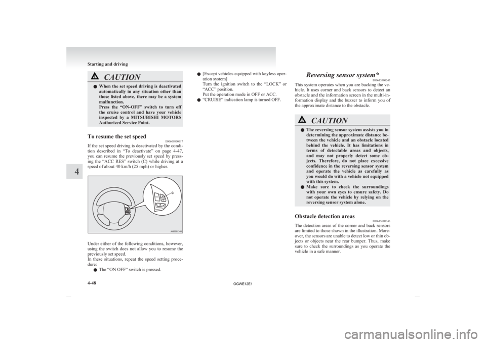
you can resume the previously set speed by press-
ing the “ACC RES” switch (C) while driving at a
speed of about 40 km/h (25 mph) or higher. Under either of the following conditions, however,
using
the switch does not allow you to resume the
previously set speed.
In these situations, repeat the speed setting proce-
dure:
l The “ON OFF” switch is pressed. l
[Except
vehicles equipped with keyless oper-
ation system]
Turn the ignition switch to the “LOCK” or
“ACC” position.
Put the operation mode in OFF or ACC.
l “CRUISE” indication lamp is turned OFF. Reversing sensor system*
E00615500345
This
system operates when you are backing the ve-
hicle. It uses corner and back sensors to detect an
obstacle and the information screen in the multi-in-
formation display and the buzzer to inform you of
the approximate distance to the obstacle. CAUTION
l
The reversing sensor system assists you in
determining the approximate distance be-
tween
the vehicle and an obstacle located
behind the vehicle. It has limitations in
terms of detectable areas and objects,
and may not properly detect some ob-
jects. Therefore, do not place excessive
confidence in the reversing sensor system
and operate the vehicle as carefully as
you would do with a vehicle not equipped
with this system.
l Make sure to check the surroundings
with your own eyes to ensure safety. Do
not operate the vehicle by relying on the
reversing sensor system alone.
Obstacle detection areas E00615600346
The detection areas of the corner and back sensors
are
limited to those shown in the illustration. More-
over, the sensors are unable to detect low or thin ob-
jects or objects near the rear bumper. Thus, make
sure to check the surroundings as you operate the
vehicle in a safe manner. Starting and driving
4-48
4
OGWE12E1
Page 203 of 378
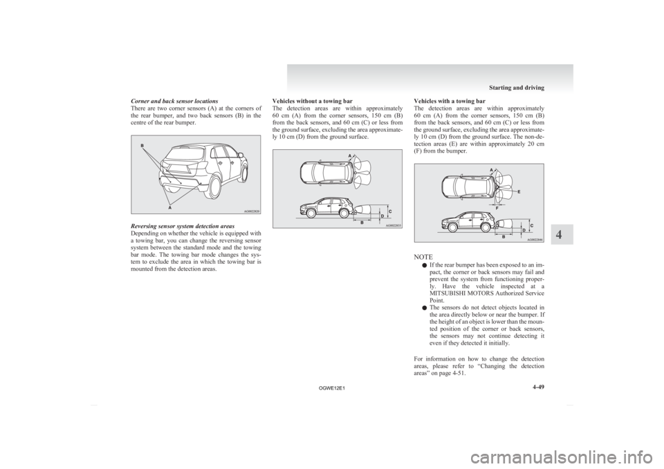
Corner and back sensor locations
There
are two corner sensors (A) at the corners of
the rear bumper, and two back sensors (B) in the
centre of the rear bumper. Reversing sensor system detection areas
Depending
on whether the vehicle is equipped with
a towing bar, you can change the reversing sensor
system between the standard mode and the towing
bar mode. The towing bar mode changes the sys-
tem to exclude the area in which the towing bar is
mounted from the detection areas. Vehicles without a towing bar
The
detection areas are within approximately
60 cm (A) from the corner sensors, 150 cm (B)
from the back sensors, and 60 cm (C) or less from
the ground surface, excluding the area approximate-
ly 10 cm (D) from the ground surface. Vehicles with a towing bar
The
detection areas are within approximately
60 cm (A) from the corner sensors, 150 cm (B)
from the back sensors, and 60 cm (C) or less from
the ground surface, excluding the area approximate-
ly 10 cm (D) from the ground surface. The non-de-
tection areas (E) are within approximately 20 cm
(F) from the bumper. NOTE
l If
the rear bumper has been exposed to an im-
pact, the corner or back sensors may fail and
prevent the system from functioning proper-
ly. Have the vehicle inspected at a
MITSUBISHI MOTORS Authorized Service
Point.
l The sensors do not detect objects located in
the area directly below or near the bumper. If
the height of an object is lower than the moun-
ted position of the corner or back sensors,
the sensors may not continue detecting it
even if they detected it initially.
For information on how to change the detection
areas, please refer to “Changing the detection
areas” on page 4-51. Starting and driving
4-49 4
OGWE12E1
Page 204 of 378
CAUTION
l
The reversing sensor system may not op-
erate properly under the following condi-
tions: • The sensors or surroundings are cov-ered with ice, snow, or mud.
• The sensors are frozen.
• The system receives ultrasonic noise from other sources (the horns of other
vehicles, motorcycle engines, brakes,
radios, pouring rain, splashing water,
tyre chains, etc.).
• The sensors are extremely hot or cold (while the vehicle is parked for a long
period of time under a blazing sun or
in cold weather).
• The vehicle tilts significantly.
• The vehicle is driven on a rough road (with a bumpy, gravel, hilly, or grassy
surface).
• The vehicle is too close to an obstacle.
• The sensors or surroundings have been wiped by hand, or stickers or ac-
cessories have been attached.
l The reversing sensor system may not prop-
erly detect the following:
• Objects that are thin, such as wirenets or ropes.
• Objects that absorb sound waves, such as snow.
• Objects that are shaped with a sharp angle.
• Objects with a smooth surface, such as glass.
• Objects that are low, such as kerb- stones. NOTE
l The
buzzer may sound lower than the normal
warning sound when the reversing sensor sys-
tem is receiving ultrasonic noise from other
sources, but this is not a malfunction. The buz-
zer will stop sounding and the system will re-
turn to normal operation after the noise is no
longer received.
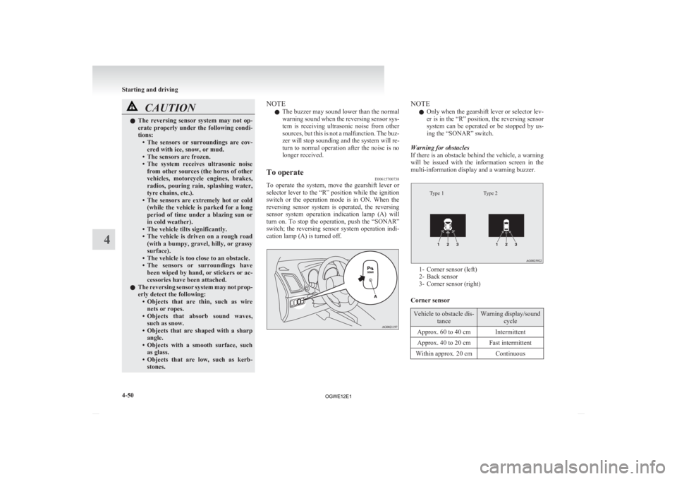
To operate E00615700738
To operate the system, move the gearshift lever or
selector
lever to the “R” position while the ignition
switch or the operation mode is in ON. When the
reversing sensor system is operated, the reversing
sensor system operation indication lamp (A) will
turn on. To stop the operation, push the “SONAR”
switch; the reversing sensor system operation indi-
cation lamp (A) is turned off. NOTE
l Only
when the gearshift lever or selector lev-
er is in the “R” position, the reversing sensor
system can be operated or be stopped by us-
ing the “SONAR” switch.
Warning for obstacles
If there is an obstacle behind the vehicle, a warning
will be issued with the information screen in the
multi-information display and a warning buzzer.
Type 2
Type 1 1- Corner sensor (left)
2-
Back sensor
3- Corner sensor (right)
Corner sensor Vehicle to obstacle dis-
tance Warning display/sound
cycle
Approx. 60 to 40 cm Intermittent
Approx. 40 to 20 cm Fast intermittent
Within approx. 20 cm Continuous Starting and driving
4-50
4
OGWE12E1
Page 205 of 378
Back sensor (vehicles without a towing bar)
Vehicle to obstacle dis-
tance Warning display/sound
cycle
Approx. 150 to 80 cm Intermittent Approx. 80 to 40 cm Fast intermittent
Within approx. 40 cm Continuous Back sensor (vehicles with a towing bar)
Vehicle to obstacle dis-
tance Warning display/sound
cycle
Approx. 150 to 100 cm Intermittent Approx. 100 to 60 cm Fast intermittentWithin approx. 60 cm Continuous CAUTION
l
The distances given are to be used for ref-
erence
only, as errors may be caused by
various factors, such as temperature, hu-
midity, or the shape of the obstacles.
NOTE l When
the sensors detect different obstacles
at the same time, the information screen in
the multi-information display indicates the di-
rections of the obstacles each sensor is detect-
ing. However, closer obstacles are given pri-
ority over other detected obstacles and the
warning buzzer sounds to inform you of clos-
er obstacles. Changing the detection areas
E00615800159
The detection areas can be changed as follows:
Vehicles with a towing bar
While
the operation of the system is stopped at the
“SONAR” switch, push the “SONAR” switch ap-
proximately 3 seconds or more, and release it. The
buzzer sounds twice to indicate that the detection
area has been changed.
Vehicles without a towing bar
While the operation of the system is stopped at the
“SONAR” switch, push the “SONAR” switch ap-
proximately 3 seconds or more, and release it. The
buzzer sounds once to indicate that the detection
area has been changed.
NOTE
l The detection area will not change if you
keep the “SONAR” switch pushed for
10 seconds or more.
l After pushing the “SONAR” switch, revers-
ing sensor system operation differs accord-
ing to the detection area setting.
• Setting when towing bar is not equippedWhen the gearshift lever or selector lever
is moved to the “R” position, the revers-
ing sensor system will operate even if cor-
ner sensor operation was stopped by push-
ing the “SONAR” switch. • Setting when towing bar is equipped
When reversing sensor system operation
was stopped by pushing the “SONAR”
switch, the reversing sensor system will
not operate until the engine has been stop-
ped even if the gearshift lever or selector
lever is moved to the “R” position.
To resume reversing sensor system opera-
tion, push the “SONAR” switch or stop
and restart the engine, and then move the
gearshift lever or selector lever to the “R”
position.
Reversing sensor system warning dis-
play E00615900277
In case there is a malfunction in the reversing sen-
sor
system, the display for the malfunctioning sen-
sor will blink and the warning buzzer will sound
for approximately 5 seconds. Even after the buzzer
has stopped sounding, the display will continue
blinking until the system reverts to the normal
state. Have the vehicle inspected at a
MITSUBISHI MOTORS Authorized Service Point.
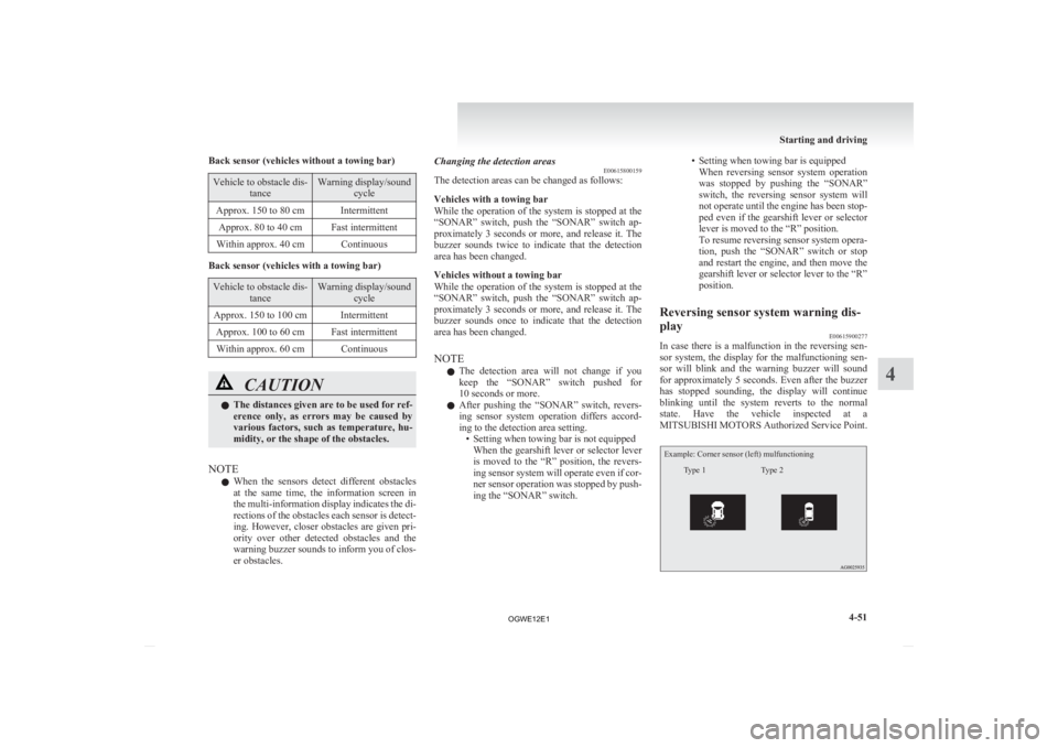
Example: Corner sensor (left) mulfunctioning
Type 2
Type 1 Starting and driving
4-51 4
OGWE12E1
Page 215 of 378
Foot/demister position
Air flows to the leg area, the windscreen and the
door windows. Demister position
Air
flows mainly to the windscreen and the door
windows. CAUTION
l
When
using the mode selection dial be-
tween the “ ” and “ ” positions, pre-
vent fogging by pressing the air selection
switch to select outside air.
(Refer to “Air selection switch” on page
5-04.)
NOTE l With
the mode selection dial between the
“ ”
and “ ” positions, the air flows main-
ly to the upper part of the passenger compart-
ment. With the mode selection dial between
the “ ”
and “ ” positions, the air flows
mainly to the leg area.
l With the mode selection dial in the “ ”
po-
sition, a small amount of air flows to the wind-
screen and the door windows.
l With the mode selection dial between the
“ ”
and “ ” positions, the air flows main-
ly to the leg area. With the mode selection di-
al between the “ ”
and “ ” positions, the
air flows mainly to the windscreen and door
windows. Heater/Air conditioning
E00700500449
The
heater/air conditioning can only be used while
the engine is running.
Control panel E00700600541
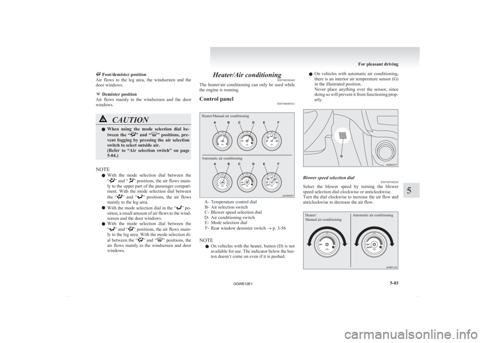
Heater/Manual air conditioning
Automatic air conditioning A- Temperature control dial
B-
Air selection switch
C- Blower speed selection dial
D- Air conditioning switch E- Mode selection dialF- Rear window demister switch ® p. 3-56
NOTE l On vehicles with the heater, button (D) is not
available for use. The indicator below the but-
ton doesn’t come on even if it is pushed. l
On
vehicles with automatic air conditioning,
there is an interior air temperature sensor (G)
in the illustrated position.
Never place anything over the sensor, since
doing so will prevent it from functioning prop-
erly. Blower speed selection dial
E00700700249
Select the blower speed by turning the blower
speed selection dial clockwise or anticlockwise.
Turn
the dial clockwise to increase the air flow and
anticlockwise to decrease the air flow.
Heater/
Manual air conditioning Automatic air conditioning For pleasant driving
5-03 5
OGWE12E1
Page 307 of 378
NOTE
l If
genuine leather is wet with water or is wash-
ed in water, wipe off water as quickly as pos-
sible with a dry, soft cloth. If left damp, mil-
dew may grow.
l The genuine leather surface may be damaged
if a nylon brush or synthetic fibre is rubbed
hard against it.
l Organic solvents such as benzine, kerosene,
alcohol and petrol, acid or alkaline solvents
may discolour the genuine leather surface.
Be sure to use neutral detergents.
l Remove dirty patches or oil substances quick-
ly as they can stain genuine leather.
l The genuine leather surface may harden and
shrink if it is exposed to direct sun for long
hours. When your vehicle is parked, place it
in the shade as much as possible.
l When the temperature of the vehicle interior
rises in summer, vinyl products left on the
genuine leather seat may deteriorate and
stick to the seat. Cleaning the exterior of your
vehicle E00900700108
If
the following is left on your vehicle, it may
cause corrosion, discolouration and stains, wash
the vehicle as soon as possible.
l Seawater, road deicing products.
l Soot and dust, iron powder from factories,
chemical substance (acids, alkalis, coal-tar,
etc.).
l Droppings from birds, carcasses of insects,
tree sap, etc.
Washing E00900902276
Chemicals contained in the dirt and dust picked up
from
the road surface can damage the paint coat
and body of your vehicle if left in prolonged contact.
Frequent washing and waxing is the best way to pro-
tect your vehicle from this damage. This will also
be effective in protecting it from environmental el-
ements such as rain, snow, salt air, etc.
Do not wash the vehicle in direct sunlight. Park the
vehicle in the shade and spray it with water to re-
move dust. Next, using an ample amount of clean
water and a car washing brush or sponge, wash the
vehicle from top to bottom.
Use a mild car washing soap if necessary. Rinse
thoroughly and wipe dry with a soft cloth. After
washing the vehicle, carefully clean the joints and
flanges of the doors, bonnet and other sections
where dirt is likely to remain. CAUTION
l
When
washing the under side of your ve-
hicle or wheel, be careful not to injure
your hands.
l If your vehicle has rain sensor wipers,
place the wiper switch lever in the “OFF”
position to deactivate the rain sensor be-
fore washing the vehicle. Otherwise, the
wipers will operate in the presence of wa-
ter spray on the windscreen and may get
damaged as a result.
l Refrain from excessively using a car wash
as its brushes may scratch the paint sur-
face, causing it to lose its gloss. Scratches
will be especially visible on darker col-
oured vehicles.
l Never spray or splash water on the electri-
cal components in the engine compart-
ment. Doing so could have an adverse ef-
fect on the engine startability.
Exercise caution also when washing the
underbody; be careful not to spray water
into the engine compartment.
l Some types of hot water washing equip-
ment apply high pressure and heat to the
vehicle. They may cause heat distortion
and damage to the vehicle resin parts and
may result in flooding of the vehicle inte-
rior.
Therefore;
• Maintain a distance of approx. 70 cmor more between the vehicle body and
the washing nozzle. Vehicle care
7-03 7
OGWE12E1
Page 308 of 378
CAUTION
• When washing around the door glass,
hold the nozzle at a distance of more
than 70 cm and at right angles to the
glass surface.
l After washing the vehicle, drive the vehi-
cle slowly while lightly depressing the
brake pedal several times in order to dry
out the brakes.
Leaving the brakes wet could result in re-
duced braking performance. Also, there
is a possibility that they could freeze up
or become inoperative due to rust, render-
ing the vehicle unable to move.
l When using an automatic car wash, pay
attention to the following items, referring
to the operation manual or consulting a
car wash operator. If the following proce-
dure is not followed, it could result in dam-
age to your vehicle.
• The outside mirrors are retracted.
• The antenna is removed.
• The wiper arms are secured in placewith tape.
• If your vehicle is equipped with a rear spoiler or roof rails, consult a car
wash operator before using the car
wash.
• If your vehicle has rain sensor wipers, place the wiper switch lever in the
“OFF” position to deactivate the rain
sensor. During cold weather
Salt
and other chemicals spread on the roads in
some areas in winter can have a harmful effect on
the vehicle body. You should therefore wash the ve-
hicle as often as possible in accordance with our
care-instructions. It is recommended to have a pres-
ervative applied and the underfloor protection
checked before and after the cold weather season.
After washing your vehicle, wipe off all water-
drops from the rubber parts around the doors to pre-
vent the doors from freezing.
NOTE
l To prevent freezing of the weatherstripping
on the doors, bonnet, etc., they should be trea-
ted with silicone spray.
Waxing E00901000863
Waxing the vehicle will help prevent the adherence
of
dust and road chemicals to the paintwork. Apply
a wax solution after washing the vehicle, or at least
once every three months to assist displacing of water.
Do not wax your vehicle in direct sunlight. You
should wax after the surfaces have cooled. CAUTION
l
Waxes
containing high abrasive com-
pounds should not be used. Such waxes re-
move rust and stains effectively from the
paintwork but they are harmful to the lus-
tre on the painted surface and the plated
surface.
Further, they are harmful to glossy surfa-
ces such as grille, garnish, mouldings, etc. CAUTION
l
Do
not use petrol or paint thinners to re-
move road tar or other contamination to
the painted surface.
l Do not apply wax to sections that have a
black mat paint coating, as doing so
could cause uneven discolouration, spots
or stains. If wax gets on such areas, wipe
it off using lukewarm water and a soft
cloth.
Polishing E00901100066
The vehicle should only be polished if the paint-
work
has become stained or lost its lustre. Do not
polish parts with a mat coating and the plastic bump-
ers. Doing so could cause stains or damage the finish.
Damaged paint E00901200054
Small cracks and scratches in the paint coat should
be
touched up as soon as possible with
MITSUBISHI touch-up paint to prevent corrosion.
Check body areas facing the road or the tyres care-
fully for damage to the paint caused by gravels,
etc. The paint code number for your vehicle can be
found on the vehicle information code plate in the
engine compartment.
Cleaning plastic parts E00901300707
Use a sponge or chamois leather.
If
a car wax adheres on a grey or black rough sur-
face of the bumper, moulding or lamps, the surface
becomes white. In such a case, wipe it off using
lukewarm water and soft cloth or chamois leather. Vehicle care
7-04
7
OGWE12E1
Page 365 of 378
Bulb capacity 8-25
Mirror Inside rear-view mirror 4-08
Outside rear-view mirrors 4-10
Modification/alterations
to the electrical or fuel sys-
tems 05
Multi-information display 3-03
OOil
Engine oil 8-04
Manual transmission oil 9-15
Rear differential oil
9-15
Transfer oil 9-15
Operation mode 1-12
Operation under adverse driving conditions 6-22
Outside rear-view mirrors 4-10
Overheating 6-04
PParking 4-07
Parking brake 4-06
Parking brake break-in 8-15
Position lamps Bulb capacity
8-24
Replacement 8-27
Power steering Fluid 9-15
Precautions to observe when using wipers and wash-
ers 3-56
Pregnant women restraint 2-14
Puncture Tyre changing 6-12
Tyre repair kit 6-06 RRear combination lamps
Bulb capacity
8-25
Replacement 8-31
Rear differential oil 9-15
Rear fog lamp Bulb capacity 8-24
Replacement 8-31
Switch 3-50
Rear room lamp Bulb capacity 8-25
Rear shelf panel 5-69
Rear turn-signal lamps Bulb capacity 8-25
Replacement 8-31
Rear window demister switch 3-56
Rear-view camera 4-52
Rear-view mirror Inside 4-08
Outside 4-10
Refill capacities 9-15
Replacement of lamp bulbs 8-24
Reversing lamps Bulb capacity 8-24
Replacement 8-31
Reversing sensor system 4-48
Roof carrier precaution 4-56
Room lamp (front) 5-62
Room lamp (rear) 5-63
Running-in recommendations 4-04
S Safe driving techniques 4-03
Seat belt 2-10
Adjustable seat belt anchor
2-12
Child restraint 2-15 Force limiter 2-15
Inspection 2-24
Pregnant women restraint
2-14
Pretensioner 2-14
Seat Adjustment 2-03
Front seat 2-03
Head restraints 2-07
Heated seats 2-06
Making a luggage compartment 2-08
Rear seat 2-06
Security alarm system 1-28
Service precaution 8-02
Side turn-signal lamp Bulb capacity 8-24
Side turn-signal lamps Replacement 8-29
Snow tyres 8-14
Spare wheel 6-12
Spark plug 9-12
Specifications 9-02
Starting 4-14
Starting and stopping the engine 1-15
Steering Power steering fluid 9-15
Steering wheel height and reach adjust-
ment 4-08
Steering wheel lock 1-15,4-14
Stop and tail lamps Replacement 8-31
Stop lamps Bulb capacity 8-24
Storage spaces 5-65
Sun visors 5-59
Sunshade 1-36
Sunshade illumination 5-64
Supplemental restraint system 2-24 Servicing 2-34 Alphabetical index
3
OGWE12E1