remote control MITSUBISHI ASX 2012 Owner's Manual (in English)
[x] Cancel search | Manufacturer: MITSUBISHI, Model Year: 2012, Model line: ASX, Model: MITSUBISHI ASX 2012Pages: 378, PDF Size: 18.2 MB
Page 4 of 378
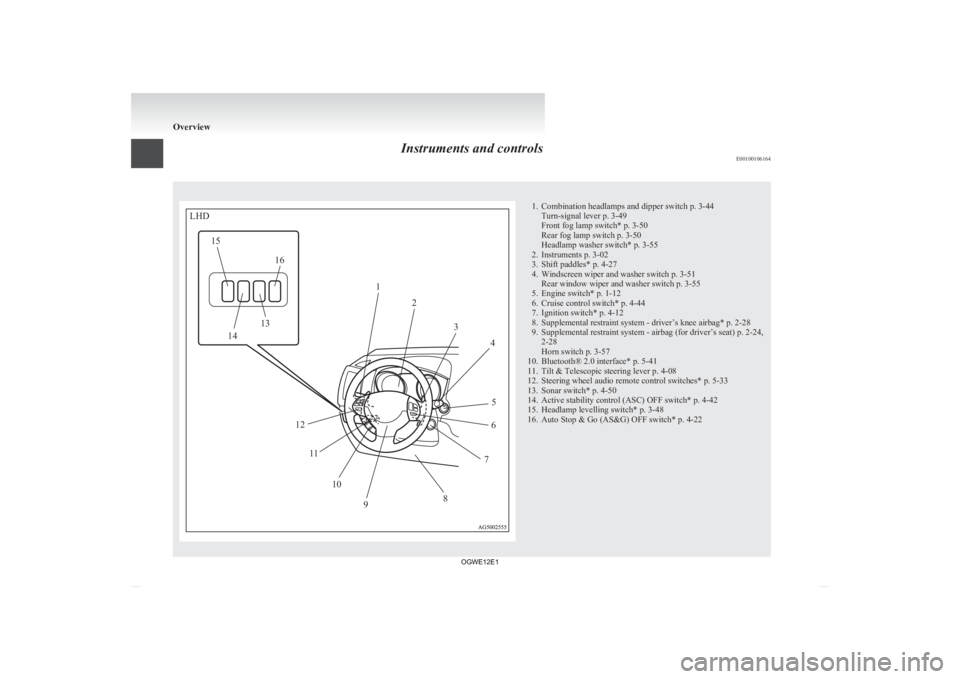
Instruments and controls
E00100106164 1. Combination headlamps and dipper switch p. 3-44
Turn-signal lever p. 3-49
Front fog lamp switch* p. 3-50
Rear fog lamp switch p. 3-50
Headlamp washer switch* p. 3-55
2.
Instruments p. 3-02
3. Shift paddles* p. 4-27
4. Windscreen wiper and washer switch p. 3-51 Rear window wiper and washer switch p. 3-55
5. Engine switch* p. 1-12
6. Cruise control switch* p. 4-44
7. Ignition switch* p. 4-12
8. Supplemental restraint system - driver’s knee airbag* p. 2-28
9. Supplemental restraint system - airbag (for driver’s seat) p. 2-24, 2-28
Horn switch p. 3-57
10. Bluetooth® 2.0 interface* p. 5-41
11. Tilt & Telescopic steering lever p. 4-08
12. Steering wheel audio remote control switches* p. 5-33
13. Sonar switch* p. 4-50
14. Active stability control (ASC) OFF switch* p. 4-42
15. Headlamp levelling switch* p. 3-48
16. Auto Stop & Go (AS&G) OFF switch* p. 4-22 OverviewLHD12
34
5
6
7
8
9
10
11
12
13
14
15
16
OGWE12E1
Page 5 of 378
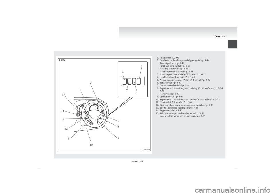
1. Instruments p. 3-02
2.
Combination headlamps and dipper switch p. 3-44Turn-signal lever p. 3-49
Front fog lamp switch* p. 3-50
Rear fog lamp switch p. 3-50
Headlamp washer switch* p. 3-55
3. Auto Stop & Go (AS&G) OFF switch* p. 4-22
4. Headlamp levelling switch* p. 3-48
5. Active stability control (ASC) OFF switch* p. 4-42
6. Sonar switch* p. 4-50
7. Cruise control switch* p. 4-44
8. Supplemental restraint system - airbag (for driver’s seat) p. 2-24, 2-28
Horn switch p. 3-57
9. Ignition switch* p. 4-12
10. Supplemental restraint system - driver’s knee airbag* p. 2-28
11. Bluetooth® 2.0 interface* p. 5-41
12. Steering wheel audio remote control switches* p. 5-33
13. Tilt & Telescopic steering lever p. 4-08
14. Engine switch* p. 1-12
15. Windscreen wiper and washer switch p. 3-51 Rear window wiper and washer switch p. 3-55 OverviewRHD12 3
4
5
6
7
8
9
10
11
12
13
14 15
OGWE12E1
Page 8 of 378
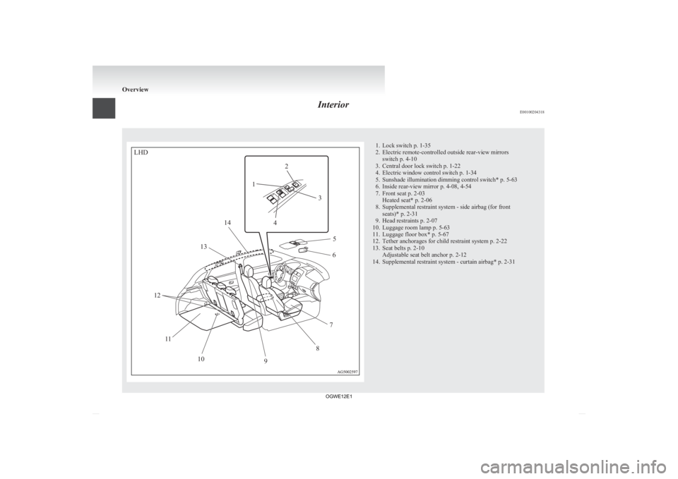
Interior
E00100204318 1. Lock switch p. 1-35
2.
Electric remote-controlled outside rear-view mirrorsswitch p. 4-10
3. Central door lock switch p. 1-22
4. Electric window control switch p. 1-34
5. Sunshade illumination dimming control switch* p. 5-63
6. Inside rear-view mirror p. 4-08, 4-54
7. Front seat p. 2-03 Heated seat* p. 2-06
8. Supplemental restraint system - side airbag (for front seats)* p. 2-31
9. Head restraints p. 2-07
10. Luggage room lamp p. 5-63
11. Luggage floor box* p. 5-67
12. Tether anchorages for child restraint system p. 2-22
13. Seat belts p. 2-10 Adjustable seat belt anchor p. 2-12
14. Supplemental restraint system - curtain airbag* p. 2-31 OverviewLHD12
3
4 5
6
7
8
9
10
11
12 13
14
OGWE12E1
Page 10 of 378
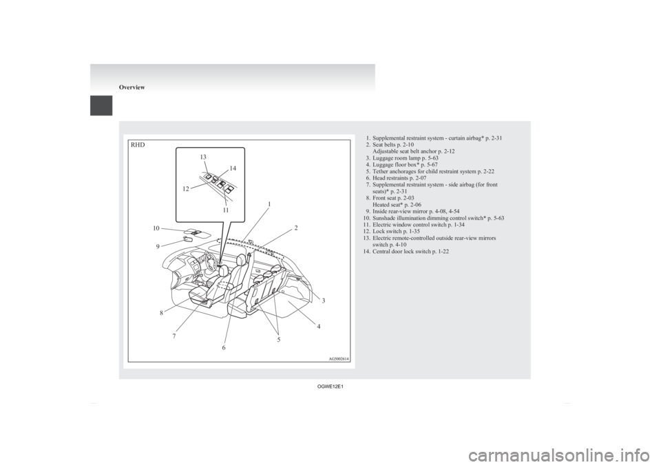
1. Supplemental restraint system - curtain airbag* p. 2-31
2.
Seat belts p. 2-10Adjustable seat belt anchor p. 2-12
3. Luggage room lamp p. 5-63
4. Luggage floor box* p. 5-67
5. Tether anchorages for child restraint system p. 2-22
6. Head restraints p. 2-07
7. Supplemental restraint system - side airbag (for front seats)* p. 2-31
8. Front seat p. 2-03 Heated seat* p. 2-06
9. Inside rear-view mirror p. 4-08, 4-54
10. Sunshade illumination dimming control switch* p. 5-63
11. Electric window control switch p. 1-34
12. Lock switch p. 1-35
13. Electric remote-controlled outside rear-view mirrors switch p. 4-10
14. Central door lock switch p. 1-22 OverviewRHD12
3
4
5
6
7
8
9
10
11
12 13
14
OGWE12E1
Page 28 of 378
l
If you lose one of them, contact your
MITSUBISHI MOTORS Authorized Service
Point as soon as possible.
To obtain a replacement or extra spare key,
take your vehicle and all remaining keys to
your MITSUBISHI MOTORS Authorized
Service Point. All the keys have to be re-reg-
istered in the immobilizer computer unit.
The immobilizer can register up to 8 differ-
ent keys. CAUTION
l
Do
not modify or add parts to the immo-
bilizer system. Doing so could cause the
immobilizer to malfunction. Keyless entry system*
E00300302317
Press
the remote control switch, and all doors and
the tailgate will be locked or unlocked as desired. It
is also possible to operate the outside rear-view mir-
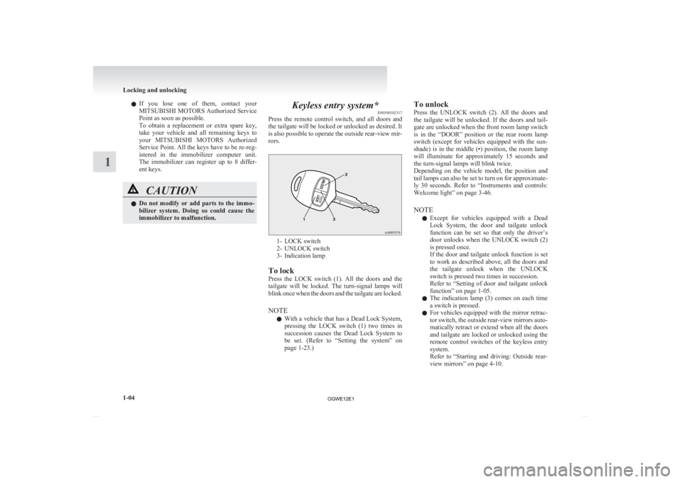
rors. 1- LOCK switch
2-
UNLOCK switch
3- Indication lamp
To lock
Press the LOCK switch (1). All the doors and the
tailgate will be locked. The turn-signal lamps will
blink once when the doors and the tailgate are locked.
NOTE l With a vehicle that has a Dead Lock System,
pressing the LOCK switch (1) two times in
succession causes the Dead Lock System to
be set. (Refer to “Setting the system” on
page 1-23.) To unlock
Press
the UNLOCK switch (2). All the doors and
the tailgate will be unlocked. If the doors and tail-
gate are unlocked when the front room lamp switch
is in the “DOOR” position or the rear room lamp
switch (except for vehicles equipped with the sun-
shade) is in the middle (•) position, the room lamp
will illuminate for approximately 15 seconds and
the turn-signal lamps will blink twice.
Depending on the vehicle model, the position and
tail lamps can also be set to turn on for approximate-
ly 30 seconds. Refer to “Instruments and controls:
Welcome light” on page 3-46.
NOTE
l Except for vehicles equipped with a Dead
Lock System, the door and tailgate unlock
function can be set so that only the driver’s
door unlocks when the UNLOCK switch (2)
is pressed once.
If the door and tailgate unlock function is set
to work as described above, all the doors and
the tailgate unlock when the UNLOCK
switch is pressed two times in succession.
Refer to “Setting of door and tailgate unlock
function” on page 1-05.
l The indication lamp (3) comes on each time
a switch is pressed.
l For vehicles equipped with the mirror retrac-
tor switch, the outside rear-view mirrors auto-
matically retract or extend when all the doors
and tailgate are locked or unlocked using the
remote control switches of the keyless entry
system.
Refer to “Starting and driving: Outside rear-
view mirrors” on page 4-10. Locking and unlocking
1-04
1
OGWE12E1
Page 29 of 378
l
If the UNLOCK switch (2) is pressed and no
door or tailgate is opened within approximate-
ly 30 seconds, relocking will automatically
occur.
l It is possible to modify functions as follows:
For further information, please contact your
MITSUBISHI MOTORS Authorized Service
Point.
On vehicles equipped with MITSUBISHI
Multi-Communication System (MMCS),
screen operations can be used to make the ad-
justment. Refer to the separate owner’s man-
ual for details.
• The time for automatic relocking can bechanged.
• The confirmation function (flashing of the turn-signal lamps) can be set to oper-
ate only when the doors and backdoor are
locked or only when the doors and back-
door are unlocked.
• The confirmation function (this indicates locking or unlocking of the doors and tail-
gate with the flash of the turn-signal
lamps) can be deactivated.
• The number of times the turn-signal lamps are flashed by the confirmation
function can be changed.
Operation of the Dead Lock System
In a vehicle that has a Dead Lock System, it is pos-
sible to set the Dead Lock System using the remote
controller.
(Refer to “Dead Lock System” on page 1-23.) Operation of the outside rear-view mir-
rors
(Vehicles equipped with mirror re-
tractor switch) E00310800135
To fold
Within 30 seconds of locking the doors and tailgate
using the LOCK switch (1), press the LOCK
switch twice rapidly to fold the outside rear-view
mirrors.
To extend
Within 30 seconds of unlocking the doors and tail-
gate using the UNLOCK switch (2), press the UN-
LOCK switch twice rapidly to return the outside
rear-view mirrors to their extended positions. The outside rear-view mirrors are not initially set
to
work as described above. If you want them to
work as described above, you need to set them so
that they do not retract/extend when the doors and
tailgate are locked/unlocked using the keyless en-
try system or keyless operation system.
Refer to “Starting and driving: Outside rear-view
mirrors” on page 4-10.
For details, please consult a MITSUBISHI
MOTORS Authorized Service Point.
In a vehicle equipped with the MITSUBISHI Mul-
ti-Communication System (MMCS), it is possible
to change the setting by means of screen operations.
Refer to the separate owner’s manual for details. NOTE
l The
keyless entry system does not operate in
the following conditions: • The key is left in the ignition switch.
• The door or tailgate is open. l
The
remote control switch will operate with-
in approximately 4 m from the vehicle. How-
ever, the operating range of the remote con-
trol switch may change if the vehicle is loca-
ted near a power station, or radio/TV broad-
casting station.
l If either of the following problems occurs,
the battery may be exhausted.
• The remote control switch is operated atthe correct distance from the vehicle, but
the doors and tailgate are not locked/un-
locked in response.
• The indication lamp (3) is dim or does not come on.
For further information, please contact
your MITSUBISHI MOTORS Author-
ized Service Point.
If you replace the battery yourself, refer
to “Procedure for replacing the remote
control switch battery” on page 1-06.
l If your remote control switch is lost or dam-
aged, please contact your MITSUBISHI
MOTORS Authorized Service Point for a re-
placement remote control switch.
l If you wish to add a remote control switch,
we recommend you to contact a
MITSUBISHI MOTORS Authorized Service
Point.
A maximum of 8 remote control switches are
available for your vehicle.
Setting of door and tailgate unlock
function (Except for vehicles equipped
with a Dead Lock System) E00310300130
The door and tailgate unlock function can be set to
the following two conditions. Locking and unlocking
1-05 1
OGWE12E1
Page 30 of 378
Each time the door and tailgate unlock function is
set,
a chime will sound to tell you the condition of
the door and tailgate unlock function. Number of
chimes Condition
One chime All doors and the tailgate unlock
Two chimes Driver’s door unlock only 1. Remove the key from the ignition switch.
2. Place
the combination headlamps and dipper
switch in the “OFF” position, and leave the
driver’s door open.
3. Press and hold the LOCK switch (1) for 4 to 10 seconds and then also press the UNLOCK
switch (2) during this time.
4. Release in sequence the LOCK and UN- LOCK switches within 10 seconds of press-
ing the LOCK switch in step 3.
NOTE l On vehicles equipped with MITSUBISHI
Multi-Communication System (MMCS),
screen operations can be used to make the ad-
justment. Refer to the separate owner’s man-
ual for details.
Procedure for replacing the remote
control switch battery E00309500145
1. Before
replacing the battery, remove static
electricity from your body by touching a met-
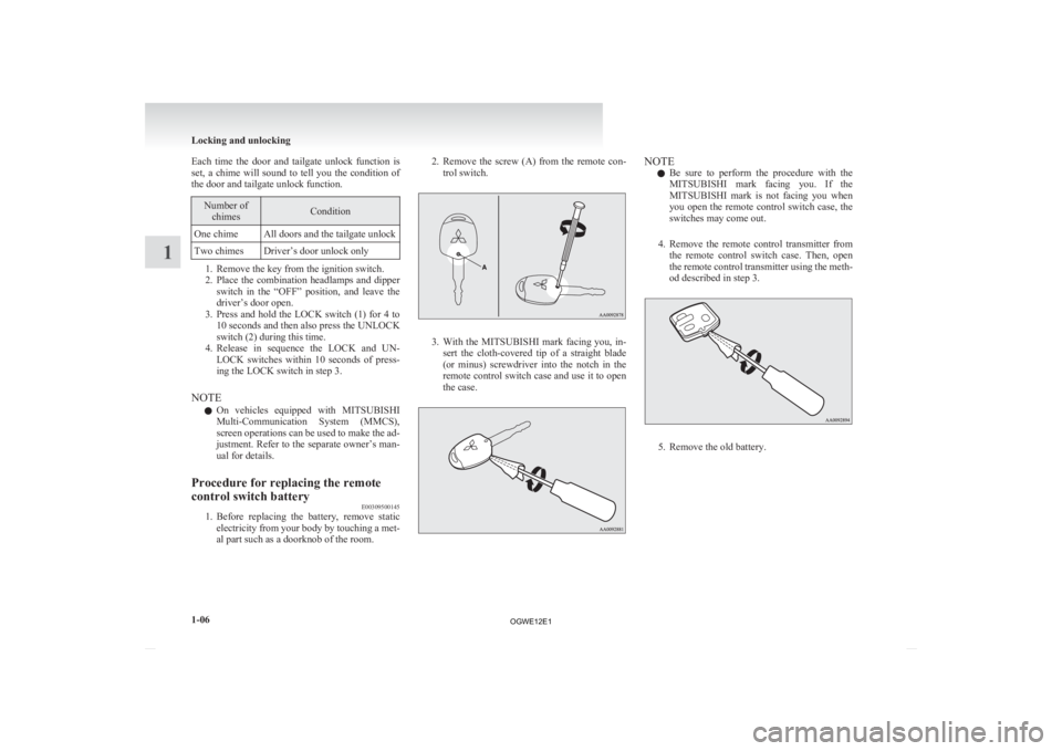
al part such as a doorknob of the room. 2. Remove
the screw (A) from the remote con-
trol switch. 3. With
the MITSUBISHI mark facing you, in-
sert the cloth-covered tip of a straight blade
(or minus) screwdriver into the notch in the
remote control switch case and use it to open
the case. NOTE
l Be
sure to perform the procedure with the
MITSUBISHI mark facing you. If the
MITSUBISHI mark is not facing you when
you open the remote control switch case, the
switches may come out.
4. Remove the remote control transmitter from the remote control switch case. Then, open
the remote control transmitter using the meth-
od described in step 3. 5. Remove the old battery.Locking and unlocking
1-06
1
OGWE12E1
Page 31 of 378
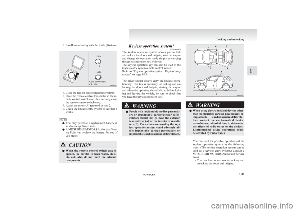
6. Install a new battery with the + side (B) down.
Coin type battery
CR1616
- side
+ side 7. Close the remote control transmitter firmly.
8.
Place the remote control transmitter in the re-mote control switch case, then securely close
the remote control switch case.
9. Attach the screw (A) removed in step 2.
10. Check the keyless entry system to see that it works.
NOTE l You may purchase a replacement battery at
an electric appliance store.
l A MITSUBISHI MOTORS Authorized Serv-
ice Point can replace the battery for you if
you prefer. CAUTION
l
When
the remote control switch case is
opened, be careful to keep water, dust,
etc. out. Also, do not touch the internal
components. Keyless operation system*
E00305600470
The
keyless operation system allows you to lock
and unlock the doors and tailgate, start the engine
and change the operation mode simply by carrying
the keyless operation key with you.
The keyless operation key can also be used as the
keyless entry system remote control switch.
Refer to “Keyless operation system: Keyless entry
system” on page 1-18.
The driver should always carry the keyless opera-
tion key. This key is necessary for locking and un-
locking the doors and tailgate, starting the engine
and otherwise operating the vehicle, so before lock-
ing and leaving the vehicle, be sure to check that
you have the keyless operation key. WARNING
l People
with implantable cardiac pacemak-
ers or implantable cardiovascular-defib-
rillators should not go near the exterior
transmitters (A) or the interior transmit-
ters (B). The radio waves used by the key-
less operation system could adversely af-
fect implantable cardiac pacemakers or
implantable cardiovascular-defibrillators. WARNING
l When using electro-medical devices other
than implantable cardiac pacemakers or
implantable cardiovascular-defibrilla-
tors, contact the electromedical device
manufacturer ahead of time to determine
the affects of radio waves on the devices.
Electromedical device operations could
be affected by radio waves.
You can limit the possible operations of the
keyless
operation system in the following
ways. (The keyless operation system can be
used as a keyless entry system.) Consult a
MITSUBISHI MOTORS Authorized Service
Point. • You can limit operations to locking andunlocking the doors and tailgate. Locking and unlocking
1-07 1
OGWE12E1
Page 39 of 378
When the operation mode is in any mode other
than
OFF, if you close all the doors and the tailgate
then try to lock the doors and tailgate by pressing
the driver’s or front passenger’s door lock/unlock
switch, or the tailgate LOCK switch, a warning is
issued with the warning display and the buzzer buzz-
ing for approximately 3 seconds and you cannot
lock the doors and tailgate.
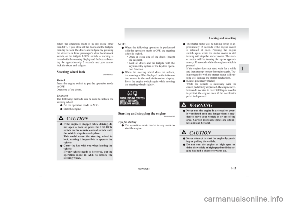
Steering wheel lock E00306800235
To lock
Press
the engine switch to put the operation mode
in OFF.
Open one of the doors.
To unlock
The following methods can be used to unlock the
steering wheel.
l Put the operation mode in ACC.
l Start the engine. CAUTION
l
If
the engine is stopped while driving, do
not open a door or press the UNLOCK
switch on the remote control switch until
the vehicle stops in a safe place.
This could cause the steering wheel to
lock, making it impossible to operate the
vehicle.
l Carry the key with you when leaving the
vehicle.
If your vehicle needs to be towed, put the
operation mode in ACC to unlock the
steering wheel. NOTE
l When
the following operation is performed
with the operation mode in OFF, the steering
wheel is locked. • Open or close one of the doors (exceptthe tailgate).
• Lock all doors and the tailgate with the keyless entry system or the keyless opera-
tion function.
l When the steering wheel does not unlock,
the warning will be displayed on the informa-
tion screen in the multi-information display.
Press the engine switch again while moving
the steering wheel slightly. Starting and stopping the engine
E00306900395
Tips for starting l The
operation mode can be in any mode to
start the engine. l
The
starter motor will be turning for up to ap-
proximately 15 seconds if the engine switch
is released at once. Pressing the engine
switch again while the starter motor is still
turning will stop the starter motor. The start-
er motor will be turning for up to approxi-
mately 30 seconds while the engine switch is
pressed.
If the engine does not start, wait for a while
and then attempt to start the engine again. Try-
ing repeatedly with the starter motor still run-
ning will damage the starter mechanism.
l [Diesel-powered vehicles]
While the vehicle is stationary with the
clutch pedal fully depressed, the engine revo-
lutions do not rise to over 3,000 rpm in order
to protect the engine even if the accelerator
pedal is depressed. WARNING
l Never
run the engine in a closed or poor-
ly ventilated area any longer than is nee-
ded to move your vehicle in or out of the
area. Carbon monoxide gases are odour-
less and can be fatal. CAUTION
l
Never
attempt to start the engine by push-
ing or pulling the vehicle.
l Do not run the engine at high rpm or
drive the vehicle at high speed until the en-
gine has had a chance to warm up. Locking and unlocking
1-15 1
OGWE12E1
Page 42 of 378
If the operation mode is in OFF and the driver’s
door
is opened with the keyless operation key in
the key slot, a warning is issued with the warning
display and the buzzer buzzing for approximately 3
seconds to remind you to remove the key.
To operate without using the keyless
operation function E00306000123
Emergency key E00307200278
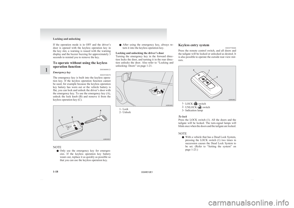
The emergency key is built into the keyless opera-
tion
key. If the keyless operation function cannot
be used, for example because the keyless operation
key battery has worn out or the vehicle battery is
flat, you can lock and unlock the driver’s door with
the emergency key. To use the emergency key (A),
unlock the lock knob (B) and remove it from the
keyless operation key (C). NOTE
l Only
use the emergency key for emergen-
cies. If the keyless operation key battery
wears out, replace it as quickly as possible so
that you can use the keyless operation key. l
After
using the emergency key, always re-
turn it into the keyless operation key.
Locking and unlocking the driver’s door
Turning the emergency key in the forward direc-
tion locks the door, and turning it in the rear direc-
tion unlocks the door. Also refer to “Locking and
unlocking: Doors” on page 1-21. 1- Lock
2-
Unlock Keyless entry system
E00307700606
Press
the remote control switch, and all doors and
the tailgate will be locked or unlocked as desired. It
is also possible to operate the outside rear-view mir-
rors. 1-
LOCK ( ) switch
2- UNLOCK ( ) switch
3-
Indication lamp
To lock
Press the LOCK switch (1). All the doors and the
tailgate will be locked. The turn-signal lamps will
blink once when the doors and the tailgate are locked.
NOTE l With a vehicle that has a Dead Lock System,
pressing the LOCK switch (1) two times in
succession causes the Dead Lock System to
be set. (Refer to “Setting the system” on
page 1-23.) Locking and unlocking
1-18
1
OGWE12E1