ignition MITSUBISHI ASX 2017 Owner's Manual (in English)
[x] Cancel search | Manufacturer: MITSUBISHI, Model Year: 2017, Model line: ASX, Model: MITSUBISHI ASX 2017Pages: 458, PDF Size: 22.98 MB
Page 350 of 458

CAUTIONl[For 2WD vehicles equipped with the Active
Stability Control (ASC)]
If the vehicle is towed with the ignition switch in the “ON” position or the operation
mode in ON and only the front wheels or on- ly the rear wheels raised off the ground (Type B or C), the ASC may operate, result-
ing in an accident.
When towing the vehicle with the rear wheels raised, turn the ignition switch to the
“ACC” position or put the operation mode in ACC.
When towing the vehicle with the front wheels raised, keep the ignition switch or the
operation mode as follows.
[Except vehicles equipped with keyless op- eration system]
The ignition switch is in the “LOCK” or
“ACC” position.
[Vehicles equipped with keyless operation system]
The operation mode is in OFF or ACC.
Towing with rear wheels off the
ground (Type B)
Place the gearshift lever in the “N” (Neutral)
position.
Turn the ignition switch to the “ACC” posi-
tion or put the operation mode in ACC and
secure the steering wheel in a straight-ahead position with a rope or tiedown strap. Neverplace the ignition switch in the “LOCK” po-
sition or put the operation mode in OFF when towing.
Towing with front wheels off the ground (Type C)
Release the parking brake.
Place the gearshift lever in the “N” (Neutral) position ( M/T) or the selector lever in the
“N” (Neutral) position (CVT).
Emergency towing
If towing service is not available in an emer-
gency, your vehicle may be temporarily tow- ed by a rope secured to the towing hook.
If your vehicle is to be towed by another ve- hicle or if your vehicle tows another vehicle,
pay careful attention to the following points:
If your vehicle is to be towed by
another vehicle
1. The front towing hook (A) is located as
shown in the illustration. Secure the tow
rope to the front towing hook.
NOTEl Do not use the tie-down hooks (B) for tow-
ing. These hooks are provided only for thepurpose of transporting the vehicle itself.
Using any part other than the designated
towing hook (A) could result in damage to
the vehicle body.
l Using a wire rope or metal chain can result
in damage to the vehicle body. It is best to
use a non-metallic rope. If you use a wire
rope or metal chain, wrap it with cloth at any point where it touches the vehicle body.
l Use care that the tow rope is kept as hori-
zontal as possible. An angled tow rope can
damage the vehicle body.
2. Keep the engine running.
If the engine is not running, perform the
following operation to unlock the steer- ing wheel.
[Except for vehicles equipped with key-
less operation system]
Towing
8-22OGAE17E2For emergencies8
Page 351 of 458

Turn the ignition switch to the “ACC” or
“ON” position ( M/T) or “ON” position
(A/T or CVT).
[For vehicles with the keyless operation
system]
Put the operation mode in ACC or ON (M/T) or ON (A/T or CVT).NOTEl For vehicles equipped with the Auto Stop &
Go (AS&G) system, press the “AS&G OFF”switch to deactivate the AS&G system be-
fore stopping the vehicle.
Refer to “To deactivate” on page 6-22.WARNINGl When the engine is not running, the brake
booster and power steering system do not
operate. This means higher brake depres- sion force and higher steering effort arerequired. Therefore, vehicle operation is more difficult than usual.CAUTIONl Do not leave the ignition switch in the
“LOCK” position or the operation mode in
OFF. The steering wheel will lock, causing loss of control.3. Place the gearshift lever in the “N”
(Neutral) position ( M/T), or the selector
lever in the “N” (Neutral) position ( A/T
or CVT).
4. Turn on the hazard warning lamps if re-
quired by law. (Follow the local driving
laws and regulations.)
5. During towing make sure that close con-
tact is maintained between the drivers of
both vehicles, and that the vehicles trav- el at low speed.CAUTIONl The person in the vehicle being towed must
pay attention to the brake lamps of the tow- ing vehicle and make sure the rope never be-
comes slack.
l Avoid sudden braking, sudden acceleration
and sharp turning; such operation could
cause damage to the towing hooks or the tow
rope.
People in the vicinity could be injured as a
result.
l When towing or being towed down a long
slope, the brakes may overheat reducing the effectiveness. In this situation, have your ve-hicle transported by a tow truck.CAUTIONl When the vehicle equipped with
A/T or
CVT is to be towed by another vehicle with
the all wheels on the ground, make sure that the towing speed and distance given below
are never exceeded, causing damage to the
transmission.
Towing speed: 40 km/h (25 mph)
Towing distance: 40 km (25 miles)
For the towing speed and the towing dis- tance, follow the local driving laws and reg- ulations.
If your vehicle tows another ve-
hicle
1. Take out the towing hook, wheel nut
wrench and jack bar.
Refer to “Tools, jack and tyre repair kit”
on page 8-06.
Towing
8-23OGAE17E2For emergencies8
Page 370 of 458

Checking battery electrolytelevel
The electrolyte level must be between the specified limit on the outside of the battery.
Replenish with distilled water as necessary.
The inside of the battery is divided into sev-
eral compartments; remove the cap from each
compartment and fill to the upper mark. Do not top up beyond the upper mark because
spillage during driving could cause damage.
Check the electrolyte level at least once every
4 weeks, depending on the operating condi- tions.
If the battery is not used, it will discharge by
itself with time.
Check it once every 4 weeks and charge with
low current as necessary.NOTEl Except for diesel-powered 1600 models, to
replenish with the distilled water, remove
the upper cover and duct.
Refer to “Removing and installing the upper cover and duct” on page 10-10.Removing and installing the
upper cover and duct
E01010700112
WARNINGl Turn the ignition switch to the “LOCK”
position or put the operation mode in
OFF.
Make sure that your clothes cannot be
caught by the fan or drive belt. Personal injury could result.
To remove
1. Remove the clips (A), and then remove
the upper cover (B).
Battery
10-10OGAE17E2Maintenance10Except for diesel-powered vehicles 1600 models Diesel-powered 1600 models
Page 383 of 458
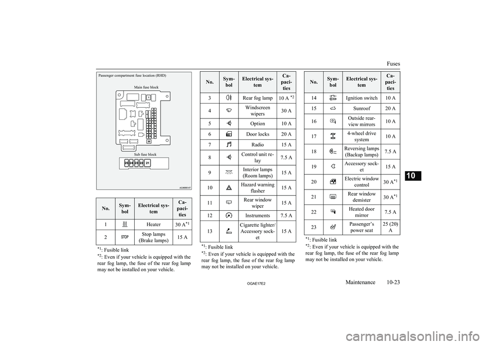
Passenger compartment fuse location (RHD)Sub fuse blockMain fuse block
No.Sym-bolElectrical sys- temCa-
paci- ties1Heater30 A *12Stop lamps
(Brake lamps)15 A*1 : Fusible link
*2 : Even if your vehicle is equipped with the
rear fog lamp, the fuse of the rear fog lamp
may not be installed on your vehicle.
No.Sym- bolElectrical sys- temCa-
paci- ties3Rear fog lamp10 A *24Windscreen
wipers30 A5Option10 A6Door locks20 A7Radio15 A8Control unit re- lay7.5 A9Interior lamps
(Room lamps)15 A10Hazard warning flasher15 A11Rear windowwiper15 A12Instruments7.5 A13
Cigarette lighter/Accessory sock- et
15 A
*1: Fusible link
*2 : Even if your vehicle is equipped with the
rear fog lamp, the fuse of the rear fog lamp
may not be installed on your vehicle.
No.Sym- bolElectrical sys- temCa-
paci- ties14Ignition switch10 A15Sunroof20 A16Outside rear-view mirrors10 A174-wheel drive system10 A18Reversing lamps(Backup lamps)7.5 A19Accessory sock- et15 A20Electric windowcontrol30 A *121Rear window
demister30 A *122Heated door
mirror7.5 A23Passenger’spower seat25 (20) A*1: Fusible link
*2 : Even if your vehicle is equipped with the
rear fog lamp, the fuse of the rear fog lamp
may not be installed on your vehicle.
Fuses
10-23OGAE17E2Maintenance10
Page 385 of 458
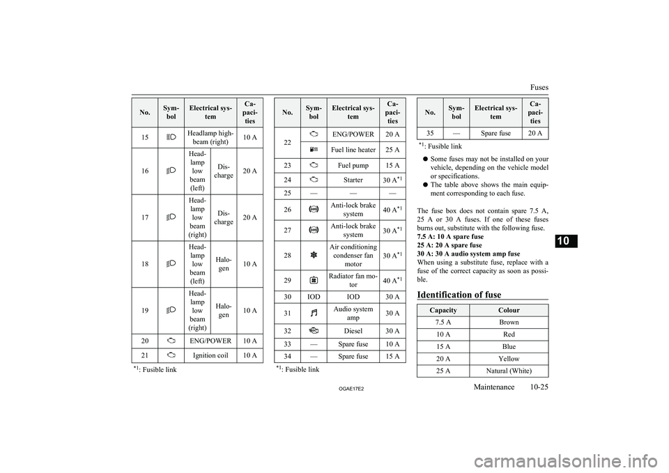
No.Sym-bolElectrical sys- temCa-
paci- ties15Headlamp high- beam (right)10 A
16
Head-lamp low
beam (left)
Dis-
charge20 A17
Head- lamp low
beam
(right)
Dis-
charge20 A18
Head- lamp low
beam (left)
Halo- gen10 A19
Head-lamp low
beam
(right)
Halo- gen10 A
20ENG/POWER10 A21Ignition coil10 A*1 : Fusible link
No.Sym-
bolElectrical sys- temCa-
paci- ties
22
ENG/POWER20 AFuel line heater25 A23Fuel pump15 A24Starter30 A *125———26Anti-lock brake
system40 A *127Anti-lock brake
system30 A *128
Air conditioning
condenser fan motor
30 A *129Radiator fan mo-
tor40 A*130IODIOD30 A31Audio system
amp30 A32Diesel30 A33—Spare fuse10 A34—Spare fuse15 A*1: Fusible link
No.Sym-
bolElectrical sys- temCa-
paci- ties35—Spare fuse20 A*1 : Fusible link
l Some fuses may not be installed on your
vehicle, depending on the vehicle model
or specifications.
l The table above shows the main equip-
ment corresponding to each fuse.
The fuse box does not contain spare 7.5 A ,
25 A or 30 A fuses. If one of these fuses burns out, substitute with the following fuse.7.5 A: 10 A spare fuse
25 A: 20 A spare fuse
30 A: 30 A audio system amp fuse
When using a substitute fuse, replace with a
fuse of the correct capacity as soon as possi- ble.
Identification of fuse
CapacityColour7.5 ABrown10 ARed15 ABlue20 AYellow25 ANatural (White)
Fuses
10-25OGAE17E2Maintenance10
Page 386 of 458

CapacityColour30 AGreen (fuse type)/Pink(fusible link type)40 AGreen (fusible link type)Fuse replacement
E01007800630
1. Before replacing a fuse, always turn off
the electrical circuit concerned and turn
the ignition switch to the “LOCK” posi-
tion or put the operation mode in OFF.
2. Remove the fuse puller (A) from the in-
side of the fuse box in the engine com-
partment.
3. Referring to the fuse load capacity table,
check the fuse pertaining to the problem.
B- Fuse is OK
C- Blown fuse
NOTEl If any system does not function but the fuse
corresponding to that system is normal, theremay be a fault in the system elsewhere. We recommend you to have your vehiclechecked.
4. Use the fuse puller to insert a new fuse
with the same capacity. Make sure you
insert the fuse into the same location in
the fuse block.
CAUTIONl If the newly inserted fuse blows again after a
short time, we recommend you to have the electrical system checked to find the causeand rectify it.
l Never use a fuse with a larger capacity than
specified or a substitute (such as a cable or
foil). Doing so could cause the circuit wires
to overheat and create a fire.Replacement of lamp bulbs
E01003101922
Before replacing a bulb, ensure the lamp isoff. Do not touch the glass part of the new
bulb with your bare fingers; the skin oil left
on the glass will evaporate when the bulb gets hot and the vapour will condense on the
reflector and dim the surface.
Replacement of lamp bulbs
10-26OGAE17E2Maintenance10
Page 420 of 458
E
Economical driving........................................... 6-02
Electric power steering system (EPS)............... 6-50
Electric window control.................................... 3-39
Electrical system............................................. 11-11
Electronic immobilizer (Anti-theft starting system)................................................ 3-03
Electronically controlled 4WD system............. 6-39
Emergency starting............................................8-02
Emergency stop signal system.......................... 6-48
Engine specifications.......................................11-10
Engine switch.................................................... 3-13
Engine Coolant..............................................10-07,11-15
Number....................................................... 11-03
Oil............................................................... 10-05
Oil and oil filter........................................... 11-15
Overheating................................................... 8-04
Specifications.............................................. 11-10
Used engine oils safety instructions and disposal information............................. 2-06
Exterior and interior lamp operation............... 10-19
F
Fluid capacities and lubricants........................ 11-15
Fluid Automatic transmission fluid...................... 11-15
Brake fluid........................................ 10-09,11-15
Clutch fluid................................................. 10-09
Engine coolant.................................. 10-07,11-15
Washer fluid..................................... 10-08,11-15
For cold and snowy weather............................10-19
Front fog lamps Bulb capacity.............................................. 10-27
Replacement................................................ 10-33
Switch........................................................... 5-55
Front room lamp
Bulb capacity.............................................. 10-28
Front seat........................................................... 4-03
Front turn-signal lamps Bulb capacity.............................................. 10-27
Replacement................................................ 10-32
Fuel consumption............................................ 11-12
Fuel Filling the fuel tank....................................... 2-03
Fuel selection................................................ 2-02
Modification/alterations to the electrical or fuel systems............................. 2-06
Tank capacity................................................ 2-03
Fuses................................................................ 10-20
Fusible links.................................................... 10-20
G
General maintenance....................................... 10-19
General vehicle data........................................ 11-04
Genuine parts.....................................................2-06
Glove box lamp Bulb capacity.............................................. 10-28
H
Hazard warning flasher switch.......................... 5-55
Hazard warning indication lamps......................5-44
Head restraints................................................... 4-07
Headlamp levelling switch................................ 5-53
Headlamp washer switch...................................5-61
Headlamps Bulb capacity.............................................. 10-27
Headlamp flasher.......................................... 5-51 Replacement..................................... 10-28,10-30Switch........................................................... 5-48
Heated mirror.................................................... 6-12
Heated seats....................................................... 4-06
Heater................................................................ 7-03
High-mounted stop lamp Bulb capacity.............................................. 10-28
Replacement................................................ 10-38
Hill start assist................................................... 6-45
Hinges and latches lubrication........................ 10-19
Horn switch....................................................... 5-63
I
If the vehicle breaks down................................ 8-02
Ignition switch................................................... 6-12
Indication lamps................................................ 5-44
Information screen display................................ 5-46
Inside rear-view mirror......................................6-08
Inside tailgate release........................................ 3-31
Inspection and maintenance following rough road operation........................................ 6-43
Instruments........................................................ 5-02
Interior lamps.................................................... 7-74
J
Jack.................................................................... 8-07
Alphabetical index
12- 2 OGAE17E2Alphabetical index