headlamp MITSUBISHI ASX 2017 (in English) Owner's Guide
[x] Cancel search | Manufacturer: MITSUBISHI, Model Year: 2017, Model line: ASX, Model: MITSUBISHI ASX 2017Pages: 458, PDF Size: 22.98 MB
Page 211 of 458
NOTElDriving on rough roads can cause rust on the
vehicle; wash the vehicle thoroughly as soonas possible after such use.
Climbing/descending sharp
grades
Your vehicle may not provide sufficient hill
climbing ability and engine braking on steep slopes. Avoid driving on steep slopes even
though the vehicle is a 4-wheel drive vehicle.
Driving through water
E00618900106
If the electrical circuits become wet, further operation of the vehicle will be impossible;
therefore, avoid driving through water unless absolutely necessary. If driving through wa-ter is unavoidable, use the following proce-
dure:
Check the depth of the water and the terrain before attempting to drive through it. Driveslowly to avoid creating excessive water
splashing.
CAUTIONl Never drive through water that is deep
enough to cover wheel hubs, axles or ex-
haust pipe. Do not change the gearshift lever position ( M/T) or the selector lever position
(A/T or CVT) while driving through water.
Frequent driving through water can adverse-
ly affect the life span of the vehicle; we rec- ommend you to take the necessary measuresto prepare, inspect, and repair the vehicle.
l After driving through water, apply the
brakes to be sure they are functioning prop- erly. If the brakes are wet and not function-
ing properly, dry them out by driving slowly
while lightly depressing the brake pedal. In- spect each part of the vehicle carefully.Inspection and maintenance
following rough roadoperation E00606700338
After operating the vehicle in rough road
conditions, be sure to perform the following inspection and maintenance procedures:
l Check that the vehicle has not been dam-
aged by rocks, gravel, etc.
l Carefully wash the vehicle with water.
Drive the vehicle slowly while lightly
depressing the brake pedal in order to dry out the brakes. If the brakes still do
not function properly, we recommend you to have the brakes checked as soon
as possible.
l Remove the insects, dried grass, etc.
clogging the radiator core.
l After driving through water, check the
engine, transmission and differential oil. If the oil or grease is milky or cloudy be-
cause of water contamination, it must be
replaced with new oil or grease.
l Check the inside of the vehicle. If water
entry is found, dry the carpet etc.
l Inspect the headlamps, If the headlamp
bulb is flooded with water, we recom- mend you to have it drained.Cautions on handling of 4-
wheel drive vehicles E00606802085
Tyres and wheels
Since the driving torque can be applied to the
4 wheels, the driving performance of the ve- hicle when operating in 4-wheel drive is
greatly affected by the condition of the tyres.
Inspection and maintenance following rough road operation
6-43OGAE17E2Starting and driving6
Page 219 of 458
WARNINGlDo not stop the engine while the vehicle is
moving. Stopping the engine would make the steering wheel extremely hard to turn,
possibly resulting in an accident.NOTEl During repeated full-lock turning of the
steering wheel (for example, while you are manoeuvring the vehicle into a parking space), a protection function may be activa-
ted to prevent overheating of the power steering system. This function will make the
steering wheel gradually harder to turn. In
this event, limit your turning of the steering wheel for a while. When the system has
cooled down, the steering action will return to normal.
l If you turn the steering wheel while the vehi-
cle is stationary with the headlamps on, the
headlamps may become dim. This behaviour is not abnormal. The headlamps will returnto their original brightness after a shortwhile.Electric power steering system
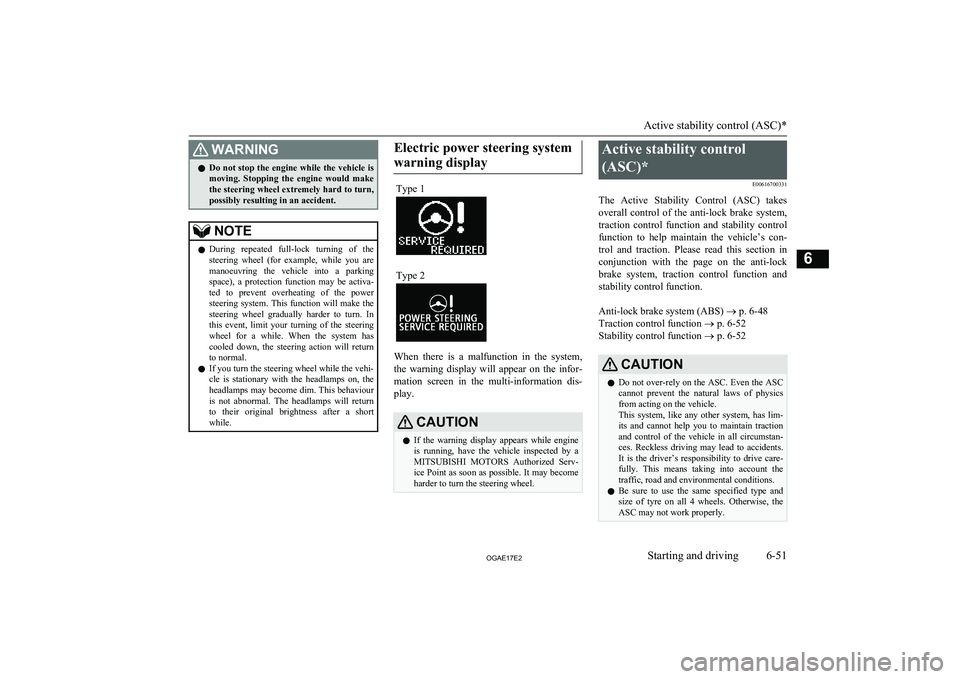
warning displayType 1Type 2
When there is a malfunction in the system, the warning display will appear on the infor-
mation screen in the multi-information dis-
play.
CAUTIONl If the warning display appears while engine
is running, have the vehicle inspected by a
MITSUBISHI MOTORS Authorized Serv-
ice Point as soon as possible. It may become
harder to turn the steering wheel.Active stability control
(ASC)* E00616700331
The Active Stability Control (ASC) takes
overall control of the anti-lock brake system, traction control function and stability control
function to help maintain the vehicle’s con-
trol and traction. Please read this section in conjunction with the page on the anti-lock
brake system, traction control function and stability control function.
Anti-lock brake system (ABS) ® p. 6-48
Traction control function ® p. 6-52
Stability control function ® p. 6-52CAUTIONl Do not over-rely on the ASC. Even the ASC
cannot prevent the natural laws of physics
from acting on the vehicle.
This system, like any other system, has lim-
its and cannot help you to maintain traction and control of the vehicle in all circumstan- ces. Reckless driving may lead to accidents. It is the driver’s responsibility to drive care-
fully. This means taking into account the traffic, road and environmental conditions.
l Be sure to use the same specified type and
size of tyre on all 4 wheels. Otherwise, the ASC may not work properly.
Active stability control (ASC)*
6-51OGAE17E2Starting and driving6
Page 238 of 458
How to use the rear-view cam-era
When you place the gearshift lever or selec- tor lever in the “R” position with the ignition
switch or the operation mode in ON, the view behind the vehicle will automatically appear
on the screen of the MITSUBISHI Multi
Communication System (MMCS) or the DIS- PLAY AUDIO. When you move the gear-
shift lever or the selector lever to any other
position, the screen will return to its original indication.
CAUTIONl The rear-view camera has a special lens that
can make objects shown on the screen ap- pear to be closer or further away than they
actually are.NOTEl Because the rear-view camera has a special
lens, the lines on the ground between park-
ing spaces may not look parallel on the screen.
l In the following situations, the screen indi-
cation may be difficult to see. There is no abnormality.
• Low light (nighttime).
• When the light of the sun or the light from
a vehicle’s headlamps shines directly into
the lens.
l If the camera is hot and is then cooled by
rain or a car wash, the lens can mist up. This
phenomenon does not indicate a malfunc- tion.
l It is not possible to fully see obstacles when
the lens is dirty. If the lens becomes conta- minated by water droplets, snow, mud or oil,
wipe off the contamination, taking care not to scratch the lens.
l Please observe the following cautions. Ig-
noring them could lead to a camera malfunc-
tion.
• Do not subject the camera to physical
shock.
• Do not apply wax to the camera.
• Do not splash the camera with boiling wa-
ter.
• Do not disassemble the camera.
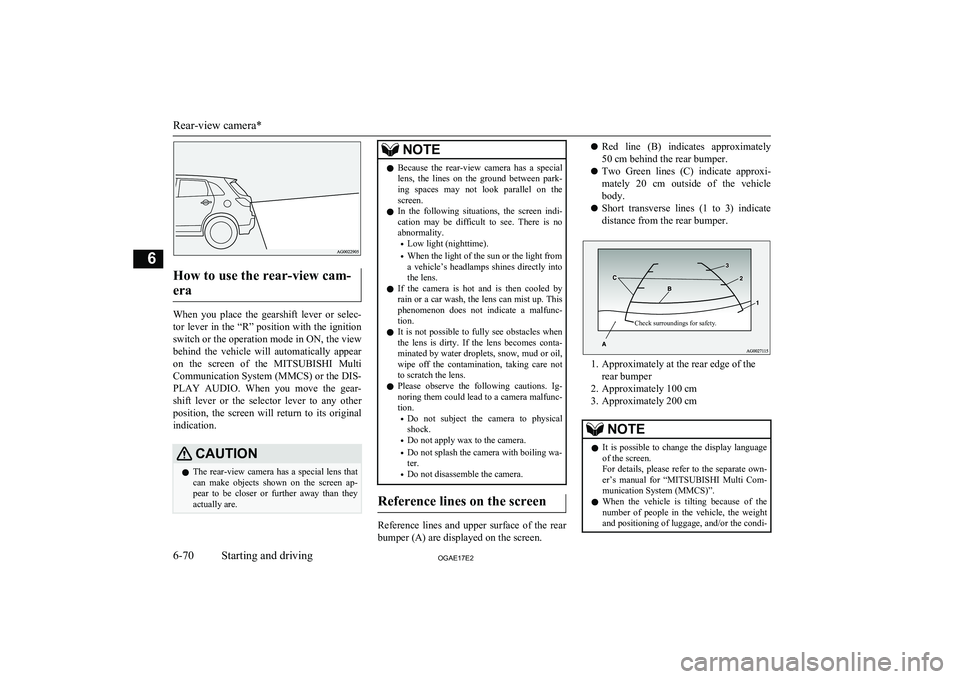
Reference lines on the screen
Reference lines and upper surface of the rear
bumper (A) are displayed on the screen.
l Red line (B) indicates approximately
50 cm behind the rear bumper.
l Two Green lines (C) indicate approxi-
mately 20 cm outside of the vehicle body.
l Short transverse lines (1 to 3) indicate
distance from the rear bumper.Check surroundings for safety.
1. Approximately at the rear edge of the rear bumper
2. Approximately 100 cm
3. Approximately 200 cm
NOTEl It is possible to change the display language
of the screen.
For details, please refer to the separate own- er’s manual for “ MITSUBISHI Multi Com-
munication System (MMCS)”.
l When the vehicle is tilting because of the
number of people in the vehicle, the weight
and positioning of luggage, and/or the condi-
Rear-view camera*
6-70OGAE17E2Starting and driving6
Page 369 of 458
NOTElThe washer fluid container serves the wind-
screen, rear window and headlamps (if soequipped).
During cold weather
To ensure proper operation of the washers at
low temperatures, use a fluid containing ananti-freezing agent.
Brake fluid/Clutch fluid*
E01000800631
The brake fluid and the clutch fluid share thereservoir tank.
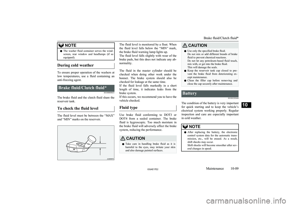
To check the fluid level
The fluid level must be between the “MAX” and “MIN” marks on the reservoir.
The fluid level is monitored by a float. When
the fluid level falls below the “MIN” mark, the brake fluid warning lamp lights up.The fluid level falls slightly with wear of the brake pads, but this does not indicate any ab-
normality.
The fluid in the master cylinder should be checked when doing other work under thebonnet. The brake system should also be checked for leakage at the same time.
If the fluid level falls markedly in a short length of time, it indicates leaks from the
brake system.
If this occurs, we recommend you to have the
vehicle checked.
Fluid type
Use brake fluid conforming to DOT3 or DOT4 from a sealed container. The brake
fluid is hygroscopic. Too much moisture in the brake fluid will adversely affect the brake
system, reducing the performance.
CAUTIONl Take care in handling brake fluid as it is
harmful to the eyes, may irritate your skin
and also damage painted surfaces.CAUTIONl Use only the specified brake fluid.
Do not mix or add different brands of brake fluid to prevent chemical reactions.
Do not let any petroleum-based fluid touch, mix with, or get into the brake fluid.
This will damage the seals.
l Keep the reservoir tank cap closed to pre-
vent the brake fluid from deteriorating ex- cept maintenance.
l Clean the filler cap before removing and
close the cap securely after maintenance.Battery
E01001203646
The condition of the battery is very important
for quick starting and to keep the vehicle’s electrical system working properly. Regularinspection and care are especially importantin cold weather.
NOTEl After replacing the battery, the electronic
control system data for the automatic trans- mission, etc., will be erased. As a result,
shift shocks may occur.
Shift shocks will become smoother after sev-
eral changes in speed.
Brake fluid/Clutch fluid*
10-09OGAE17E2Maintenance10
Page 384 of 458
No.Sym-bolElectrical sys- temCa-
paci- ties24Driver’s power seat25 (20)A25Heated seat30 A*1: Fusible link
*2 : Even if your vehicle is equipped with the
rear fog lamp, the fuse of the rear fog lamp
may not be installed on your vehicle.
l Some fuses may not be installed on your
vehicle, depending on the vehicle model
or specifications.
l The table above shows the main equip-
ment corresponding to each fuse.
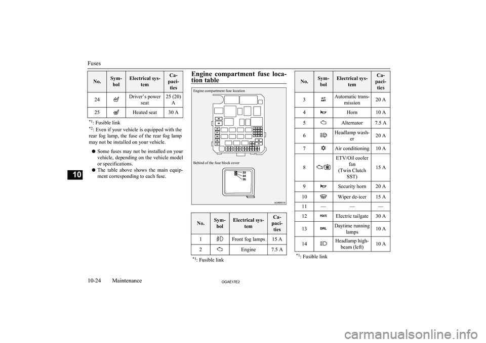
Engine compartment fuse loca-
tion tableEngine compartment fuse locationBehind of the fuse block cover
No.Sym- bolElectrical sys- temCa-
paci- ties1Front fog lamps15 A2Engine7.5 A*1 : Fusible link
No.Sym-
bolElectrical sys- temCa-
paci- ties3Automatic trans- mission20 A4Horn10 A5Alternator7.5 A6Headlamp wash- er20 A7Air conditioning10 A
8
ETV/Oil coolerfan
(Twin Clutch SST)
15 A
9Security horn20 A10Wiper de-icer15 A11———12Electric tailgate30 A13Daytime running lamps10 A14Headlamp high-beam (left)10 A*1: Fusible link
Fuses
10-24OGAE17E2Maintenance10
Page 385 of 458
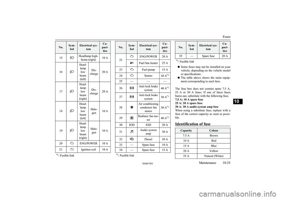
No.Sym-bolElectrical sys- temCa-
paci- ties15Headlamp high- beam (right)10 A
16
Head-lamp low
beam (left)
Dis-
charge20 A17
Head- lamp low
beam
(right)
Dis-
charge20 A18
Head- lamp low
beam (left)
Halo- gen10 A19
Head-lamp low
beam
(right)
Halo- gen10 A
20ENG/POWER10 A21Ignition coil10 A*1 : Fusible link
No.Sym-
bolElectrical sys- temCa-
paci- ties
22
ENG/POWER20 AFuel line heater25 A23Fuel pump15 A24Starter30 A *125———26Anti-lock brake
system40 A *127Anti-lock brake
system30 A *128
Air conditioning
condenser fan motor
30 A *129Radiator fan mo-
tor40 A*130IODIOD30 A31Audio system
amp30 A32Diesel30 A33—Spare fuse10 A34—Spare fuse15 A*1: Fusible link
No.Sym-
bolElectrical sys- temCa-
paci- ties35—Spare fuse20 A*1 : Fusible link
l Some fuses may not be installed on your
vehicle, depending on the vehicle model
or specifications.
l The table above shows the main equip-
ment corresponding to each fuse.
The fuse box does not contain spare 7.5 A ,
25 A or 30 A fuses. If one of these fuses burns out, substitute with the following fuse.7.5 A: 10 A spare fuse
25 A: 20 A spare fuse
30 A: 30 A audio system amp fuse
When using a substitute fuse, replace with a
fuse of the correct capacity as soon as possi- ble.
Identification of fuse
CapacityColour7.5 ABrown10 ARed15 ABlue20 AYellow25 ANatural (White)
Fuses
10-25OGAE17E2Maintenance10
Page 387 of 458
CAUTIONlBulbs are extremely hot immediately after
being turned off.
When replacing a bulb, wait for it to cool
sufficiently before touching it. You could otherwise be burnt.
l Do not install commercially available LED-
type bulbs.
Commercially available LED-type bulbs
could adversely affect the operation of the vehicle, such as by preventing the lamps andother vehicle equipment from operating
properly.NOTEl If you are unsure of how to carry out the
work as required, we recommend you to consult a specialist.
l Be careful not to scratch the vehicle body
when removing a lamp or lens.
l When it rains or when the vehicle has been
washed, the inside of the lens sometimes be-
comes foggy. This is the same phenomenon as when window glass mists up on a humid
day, and does not indicate a functional prob- lem.
When the lamp is switched on, the heat will
remove the fog. However, if water gathers inside the lamp, we recommend you to havethe lamp checked.Bulb capacity
E01003200290
When replacing a bulb, use a new bulb with
the same wattage and colour.
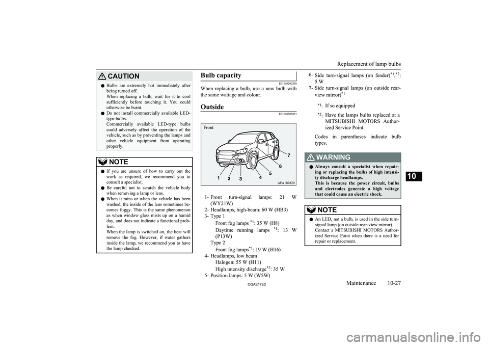
Outside
E01003305023
1- Front turn-signal lamps: 21 W
(WY21W)
2- Headlamps, high-beam: 60 W (HB3) 3- Type 1
Front fog lamps *1
: 35 W (H8)
Daytime running lamps *1
: 13 W
(P13W)
Type 2
Front fog lamps *1
: 19 W (H16)
4- Headlamps, low beam Halogen: 55 W (H11)
High intensity discharge *2
: 35 W
5- Position lamps: 5 W (W5W)
6- Side turn-signal lamps (on fender) *1
,*2
:
5 W
7- Side turn-signal lamps (on outside rear-
view mirror) *1*1
:If so equipped*2:Have the lamps bulbs replaced at a
MITSUBISHI MOTORS Author-
ized Service Point.
Codes in parentheses indicate bulb
types.
WARNINGl Always consult a specialist when repair-
ing or replacing the bulbs of high intensi- ty discharge headlamps.
This is because the power circuit, bulbs
and electrodes generate a high voltage that could cause an electric shock.NOTEl An LED, not a bulb, is used in the side turn-
signal lamp (on outside rear-view mirror).
Contact a MITSUBISHI MOTORS Author-
ized Service Point when there is a need for
repair or replacement.
Replacement of lamp bulbs
10-27OGAE17E2Maintenance10 Front
Page 388 of 458
NOTElFor the side turn-signal lamp (on fender), it
is not possible to repair or replace just the
bulb.
Contact a MITSUBISHI MOTORS Author-
ized Service Point when there is a need for
repair or replacement.
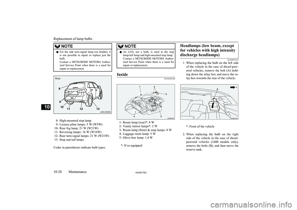
8- High-mounted stop lamp
9- Licence plate lamps: 5 W (W5W)
10- Rear fog lamp: 21 W (W21W)
11- Reversing lamps: 16 W (W16W)
12- Rear turn-signal lamps: 21 W (W21W) 13- Stop and tail lamps
Codes in parentheses indicate bulb types.
NOTEl An LED, not a bulb, is used in the stop
lamp/tail lamp and high-mounted stop lamp.
Contact a MITSUBISHI MOTORS Author-
ized Service Point when there is a need for
repair or replacement.Inside
E01003403466
1- Room lamp (rear)*: 8 W
2- Vanity mirror lamps*: 2 W
3- Room lamp (front) & map lamps: 8 W
4- Luggage room lamp: 5 W
5- Glove box lamp: 1.4 W
*: If so equipped
Headlamps (low beam, exceptfor vehicles with high intensity discharge headlamps)
E01009301522
1. When replacing the bulb on the left side
of the vehicle in the case of diesel-pow-
ered vehicles, remove the bolt (A) hold- ing down the relay box and move the re-
lay box towards the rear of the vehicle.
*: Front of the vehicle
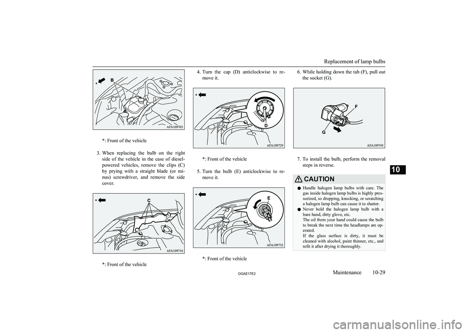
2. When replacing the bulb on the right
side of the vehicle in the case of diesel-
powered vehicles (1600 models only), remove the bolts (B), and then move thereserve tank.
Replacement of lamp bulbs
10-28OGAE17E2Maintenance10 Rear
Page 389 of 458
*: Front of the vehicle
3. When replacing the bulb on the right
side of the vehicle in the case of diesel-
powered vehicles, remove the clips (C)
by prying with a straight blade (or mi- nus) screwdriver, and remove the side
cover.
*: Front of the vehicle
4. Turn the cap (D) anticlockwise to re-
move it.
*: Front of the vehicle
5. Turn the bulb (E) anticlockwise to re-
move it.
*: Front of the vehicle
6. While holding down the tab (F), pull out
the socket (G).
7. To install the bulb, perform the removal
steps in reverse.
CAUTIONl Handle halogen lamp bulbs with care. The
gas inside halogen lamp bulbs is highly pres- surized, so dropping, knocking, or scratching
a halogen lamp bulb can cause it to shatter.
l Never hold the halogen lamp bulb with a
bare hand, dirty glove, etc.
The oil from your hand could cause the bulb to break the next time the headlamps are op-
erated.
If the glass surface is dirty, it must be cleaned with alcohol, paint thinner, etc., and
refit it after drying it thoroughly.
Replacement of lamp bulbs
10-29OGAE17E2Maintenance10
Page 390 of 458
Headlamps (low beam, for ve-hicles with high intensity dis- charge headlamps)
E01010100132
Do not attempt to disassemble or repair head- lamps, and do not attempt to replace their
bulbs.
WARNINGl A high voltage is present in the power cir-
cuit and in the bulbs and bulb terminals. To avoid the risk of an electric shock, con- tact a MITSUBISHI MOTORS Author-
ized Service Point whenever repair or re- placement is necessary.Headlamps (High-beam)
E01009400135
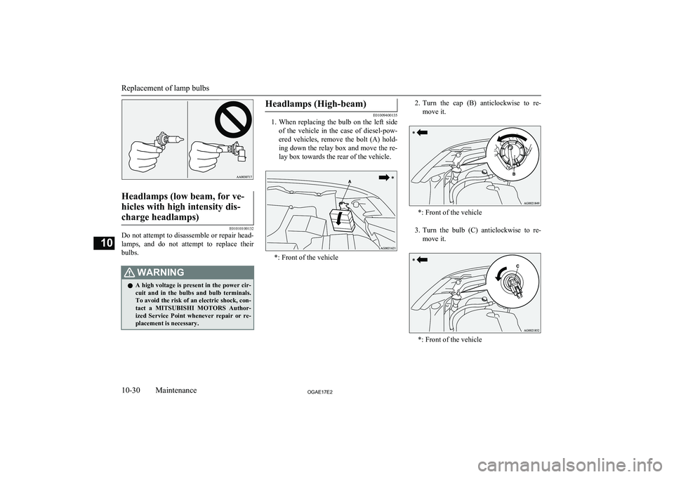
1. When replacing the bulb on the left side
of the vehicle in the case of diesel-pow-
ered vehicles, remove the bolt (A) hold-
ing down the relay box and move the re- lay box towards the rear of the vehicle.
*: Front of the vehicle
2. Turn the cap (B) anticlockwise to re-
move it.
*: Front of the vehicle
3. Turn the bulb (C) anticlockwise to re-
move it.
*: Front of the vehicle
Replacement of lamp bulbs
10-30OGAE17E2Maintenance10