brake MITSUBISHI COLT 2006 Service Manual PDF
[x] Cancel search | Manufacturer: MITSUBISHI, Model Year: 2006, Model line: COLT, Model: MITSUBISHI COLT 2006Pages: 364, PDF Size: 11.65 MB
Page 344 of 364
GENERAL INFORMATION
BASIC BRAKE SYSTEM35A-4
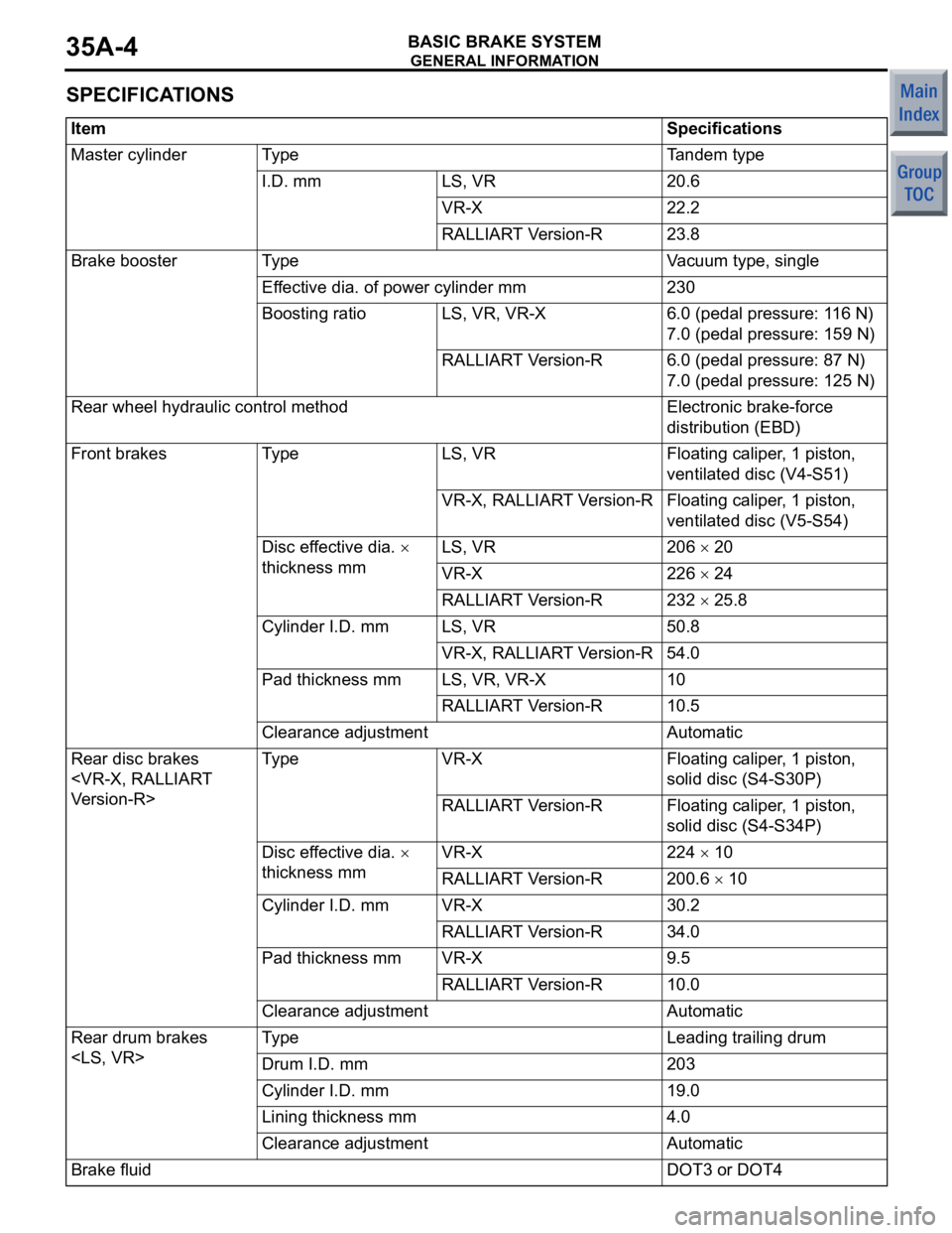
SPECIFICATIONS
ItemSpecifications
Master cylinderTy p eTandem type
I.D. mmLS, VR20.6
VR-X22.2
RALLIART Version-R23.8
Brake boosterTy p eVacuum type, single
Effective dia. of power cylinder mm230
Boosting ratioLS, VR, VR-X6.0 (pedal pressure: 116 N)
7.0 (pedal pressure: 159 N)
RALLIART Version-R6.0 (pedal pressure: 87 N)
7.0 (pedal pressure: 125 N)
Rear wheel hydraulic control methodElectronic brake-force
distribution (EBD)
Front brakesTy p eLS, VRFloating caliper, 1 piston,
ventilated disc (V4-S51)
VR-X, RALLIART Version-RFloating caliper, 1 piston,
ventilated disc (V5-S54)
Disc effective dia. ×
thickness mmLS, VR206 × 20
VR-X226 × 24
RALLIART Version-R232 × 25.8
Cylinder I.D. mmLS, VR50.8
VR-X, RALLIART Version-R54.0
Pad thickness mmLS, VR, VR-X10
RALLIART Version-R10.5
Clearance adjustmentAutomatic
Rear disc brakes
Ty p eVR-XFloating caliper, 1 piston,
solid disc (S4-S30P)
RALLIART Version-RFloating caliper, 1 piston,
solid disc (S4-S34P)
Disc effective dia. ×
thickness mmVR-X224 × 10
RALLIART Version-R200.6 × 10
Cylinder I.D. mmVR-X30.2
RALLIART Version-R34.0
Pad thickness mmVR-X9.5
RALLIART Version-R10.0
Clearance adjustmentAutomatic
Rear drum brakes
Ty p eLeading trailing drum
Drum I.D. mm203
Cylinder I.D. mm19.0
Lining thickness mm4.0
Clearance adjustmentAutomatic
Brake fluidDOT3 or DOT4
Page 345 of 364
CONSTRUCTION DESCRIPTION
BASIC BRAKE SYSTEM35A-5
CONSTRUCTION DESCRIPTION
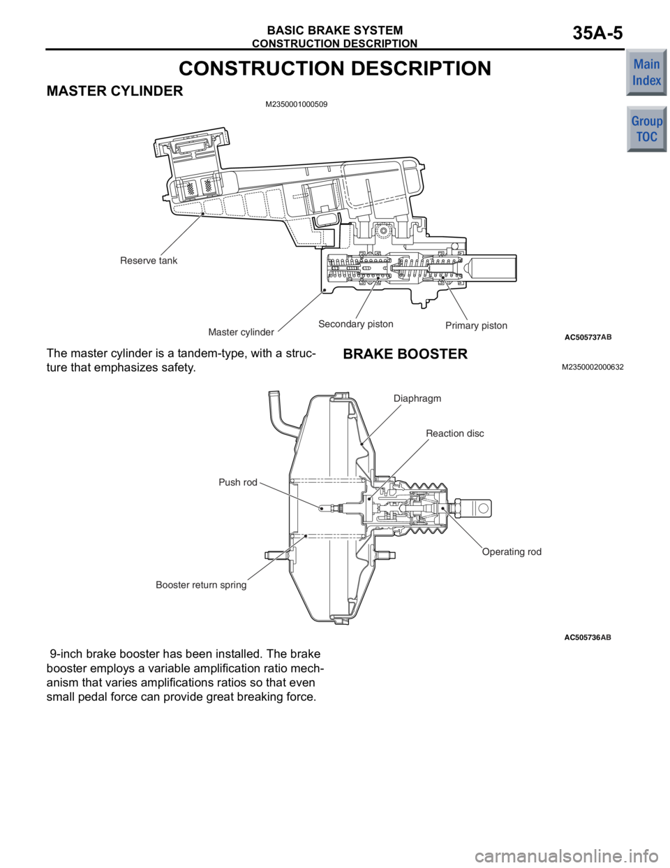
MASTER CYLINDERM2350001000509
AC505737ABMaster cylinder
Reserve tank
Primary piston
Secondary piston
The master
cylind e r is a t andem-typ e, with a stru c-
ture that emp hasizes sa fety .
BRAKE BOOSTER
M23500020 0063 2
AC505736AB
Reaction disc
Booster return spring Push rod
Diaphragm
Operating rod
9-inch brake booste r has been inst alled. T he brake
booster employs a
variable amplification ratio mech
-
anism that va ries amplifications ratios so that e v en
sma
ll p edal force can provide gre a t brea kin g force.
Page 346 of 364
CONSTRUCTION DESCRIPTION
BASIC BRAKE SYSTEM35A-6
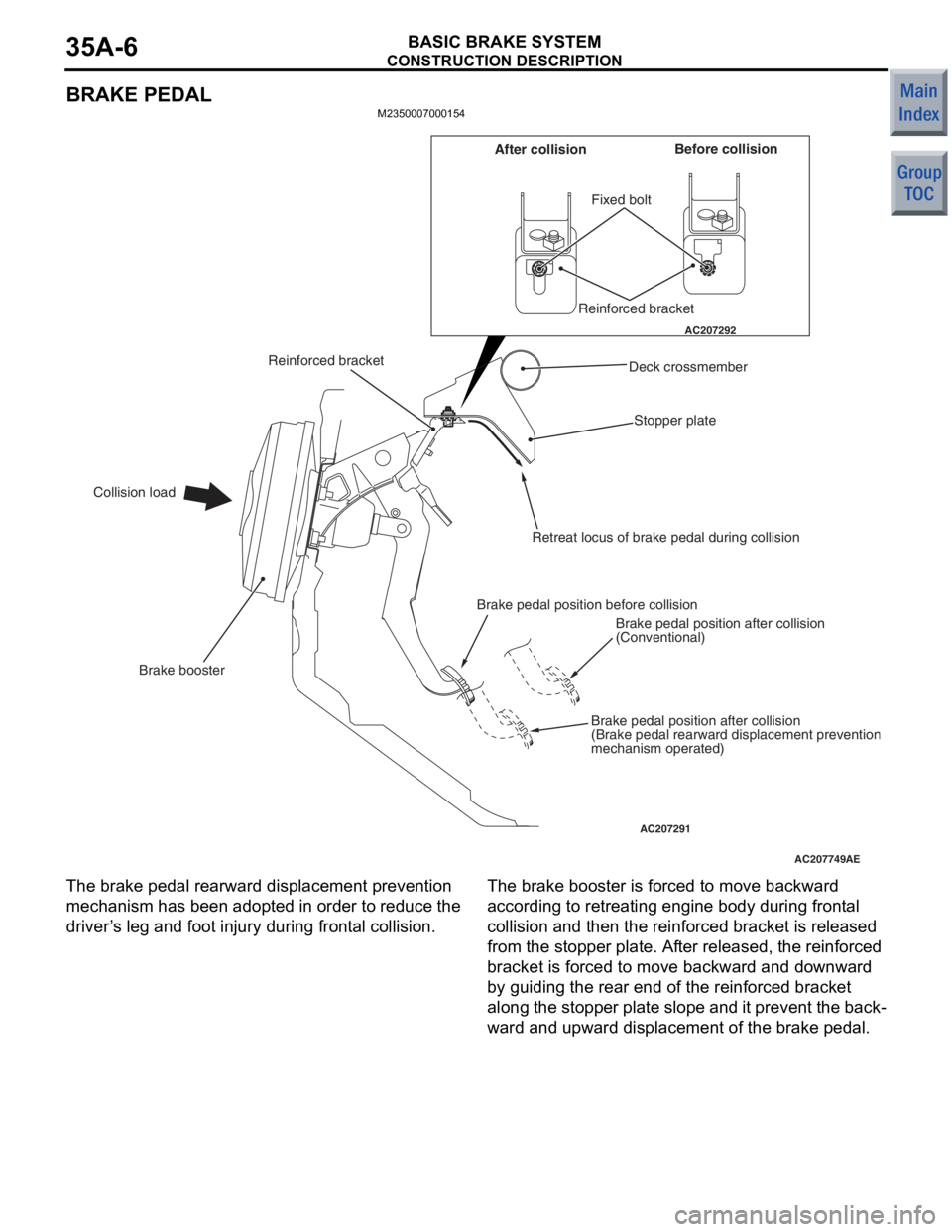
BRAKE PEDAL
M2350007000154
AC207749
AC207292
AC207291AE
Fixed bolt
Stopper plate
Brake booster
Collision load Before collision
After collision
Reinforced bracket
Deck crossmember
Retreat locus of brake pedal during collision
Brake pedal position before collision Brake pedal position after collision
(Conventional)
Brake pedal position after collision
(Brake pedal rearward displacement preventio
nmechanism operated)
Reinforced bracket
The bra
k e pe dal re arward displacement preve n tion
mechanism
has been adop ted in ord e r to reduce the
driver
’ s le g and foot injury during fron t a l co llisio n .The brak e bo oste r is force d to move backward
accordin
g to ret r eatin g engine bo dy d u ring front al
collision a
nd the n the r e info rced b r acket is release d
from
the stopper plat e. Af ter release d , the reinf o rced
bracket is forced to
move backward and do wn wa rd
by gu
iding the rear end of the reinf o rced bracket
along
the stoppe r plate slo pe and it preve n t the back
-
ward and upward displace ment of the b r ake pedal.
Page 347 of 364
CONSTRUCTION DESCRIPTION
BASIC BRAKE SYSTEM35A-7
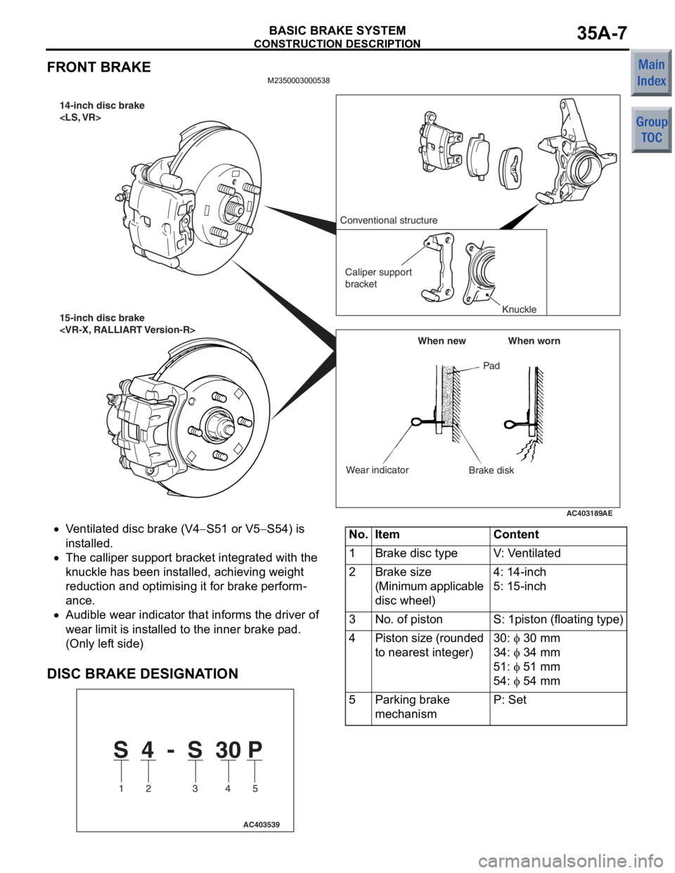
FRONT BRAKE
M2350003000538
AC403189AE
14-inch disc brake
15-inch disc brake
Brake disk
Wear indicator When new When worn
Conventional structure
Caliper support
bracket Knuckle
•Ventilate d disc b r ake (V4−S51 or V5−S54) is
in
st
alled.
•The callipe r sup port bra c ket int egrated with the
kn
uckle h a s be en in st alled, achie v in g weigh t
redu
ction and optimising it for b r ake perform
-
ance.
•Audible wear indicat o r that informs th e driver of
wear limit is inst
alle d to th e inn e r brake p ad.
(Only lef
t side)
DISC BRAKE DESIGNA T ION
S 4 - S 30 P
1 2 3 4 5
AC403539
No.ItemContent
1Brake disc typeV: Ventilated
2Brake size
(Minimum applicable
disc wheel)4: 14-inch
5: 15-inch
3No. of pistonS: 1piston (floating type)
4Piston size (rounded
to nearest integer)30: φ 30 mm
34: φ 34 mm
51: φ 51 mm
54: φ 54 mm
5Parking brake
mechanismP: Set
Page 348 of 364
CONSTRUCTION DESCRIPTION
BASIC BRAKE SYSTEM35A-8
REAR BRAKE
M2350004000531
AC403060AD
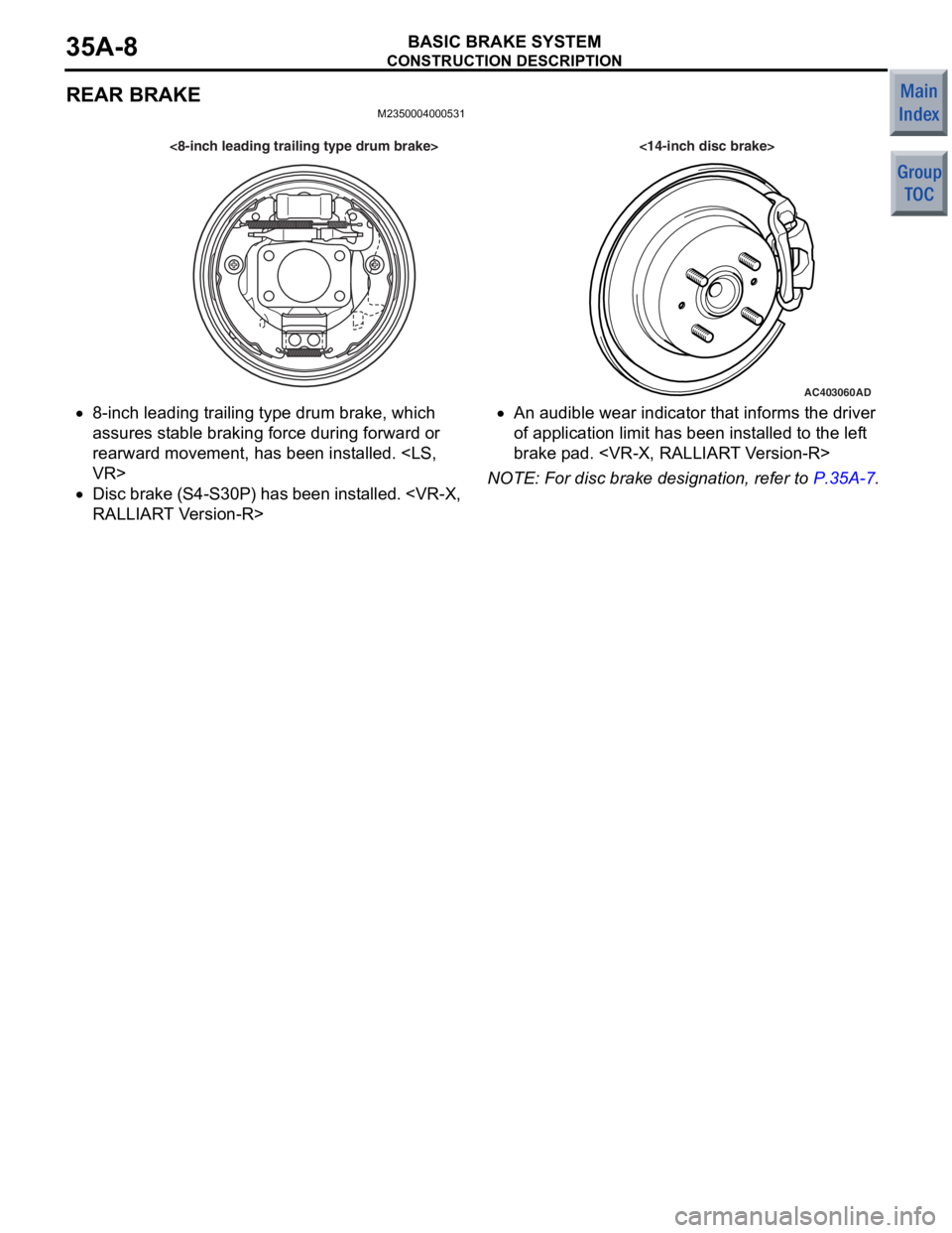
<8-inch leading trailing type drum brake> <14-inch disc brake>
•8-inch leading tra iling type drum brake, which
assure
s st ab le bra k in g force during forward or
rearward
movement, ha s bee n inst alle d.
•Disc brake (S4 - S3 0 P ) ha s be en in st a l le d.
T V e rsion - R>
•An audible wear indicator th at in forms the d r ive r
of a
pplication limit has been inst a lled to the lef t
brake p
ad.
NOTE: For d i sc brake de sign ation , refer t o P.35A-7.
Page 350 of 364
CVT
CONTINUOUSLY VARIABLE TRANSMISSION (CVT)23-2
CVT
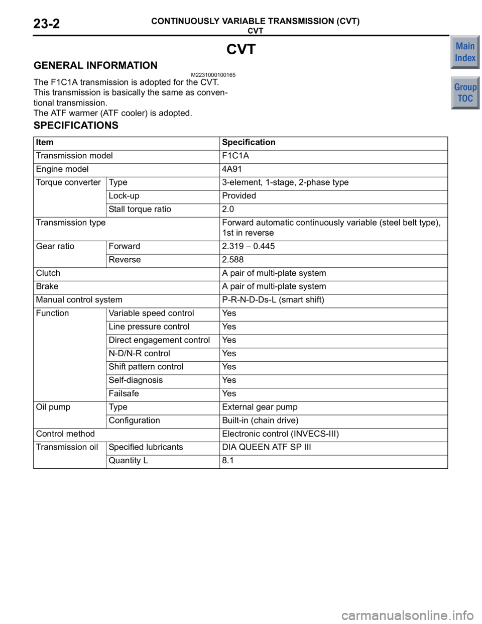
GENERAL INFORMATIONM2231000100165
The F1C1A transmission is adopted for the CVT.
This transmission is basically the same as conven
-
tional transmission.
The ATF warmer (ATF cooler) is adopted.
SPECIFICATIONS
ItemSpecification
Transmission modelF1C1A
Engine model4A91
Torque converterTy p e3-element, 1-stage, 2-phase type
Lock-upProvided
Stall torque ratio2.0
Transmission typeForward automatic continuously variable (steel belt type),
1st in reverse
Gear ratioForward2.319 − 0.445
Reverse2.588
ClutchA pair of multi-plate system
BrakeA pair of multi-plate system
Manual control systemP-R-N-D-Ds-L (smart shift)
FunctionVariable speed controlYe s
Line pressure controlYe s
Direct engagement controlYe s
N-D/N-R controlYe s
Shift pattern controlYe s
Self-diagnosisYe s
FailsafeYe s
Oil pumpTy p eExternal gear pump
ConfigurationBuilt-in (chain drive)
Control methodElectronic control (INVECS-III)
Transmission oilSpecified lubricantsDIA QUEEN ATF SP III
Quantity L8.1
Page 356 of 364

TRANSMISSION CONTROL
CONTINUOUSLY VARIABLE TRANSMISSION (CVT)23-8
CVT ERRONEOUS OPERATION PREVENTION MECHANISMS
M2232003000104
SHIFT LOCK MECHANISM
Only when the following two conditions are satisfied,
the selector lever can be shifted from the P position
to another position:•When the brake pedal is depressed
•When the ignition key is in other than the LOCK
(OFF) position
When the brake pedal is not depressed
AC206902
AB
Brake pedal
Shiftlock cable
Stopper
Lever
Rod
Lock cam
Detent pin
When the se lect or lever is in the P po sit i on wit h the
brake
pedal not d epressed, the shif tlock cable sto p
-
per keep s the lever lo cke d so that th e rod a nd lo ck
cam do no
t move.
As a result of this, th e pushbutto n of th e select or
lever linked
to the detent pin canno t be p r essed and
the selector le
ver canno t be shif ted f r om th e P posi
-
tion to anot her position.
When the brake pe dal is depressed
AC206903
AB
Brake pedal
Shiftlock cable
Stopper
Lever
RodLock cam
Detent pin
When th
e brake ped al is dep ressed, th e sto pper is
pulled by the shif
tlo c k cable so that t he le ver
beco
m es unlo c ked.
Then the lock cam linked to the ro d can also rot a te
so th
at the sele ctor leve r can be shif ted fro m th e P
position
to ano ther po sition by pressing the push but
-
ton.
NOTE: Whe n the b r ake pedal is depressed with th e
ignition key in th e LOCK (OFF) po sition, th e select or
le
ve
r ca nn ot b e sh if te d fro m th e P p o sition t o an oth e r
position .