GENERAL INFORMATION
BASIC BRAKE SYSTEM35A-3
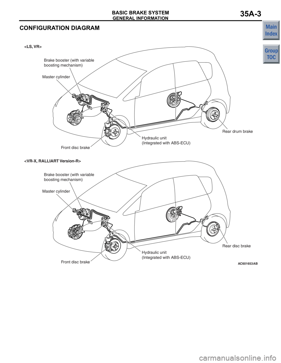
CONFIGURATION DIAGRAM
AC601653
Brake booster (with variable
boosting mechanism)
Hydraulic unit
(Integrated with ABS-ECU)
Master cylinder
Front disc brake Rear drum brake
Brake booster (with variable
boosting mechanism)
Hydraulic unit
(Integrated with ABS-ECU)
Master cylinder
Front disc brake Rear disc brake
AB
CVT
CONTINUOUSLY VARIABLE TRANSMISSION (CVT)23-3
ELECTRONIC CONTROL SYSTEM
EEPROM
M2231012000024
Because EEPROM has been used, even if the bat-
tery terminals or control unit connectors are discon-
nected, the necessary learned values are stored in
the engine-CVT-ECU to prevent a loss of shift qual
-
ity. (Initialisation is available by M.U.T.-III).
CONTROLLER AREA NETWORK (CAN)
COMMUNICATION
M2231017000018
CAN* communication has been adopted for commu-
nication with other ECUs in order to decrease the
number of wires and ensure information transmis
-
sion. For CVT control, the engine-CVT-ECU receives
the following signals.
CAN COMMUNICATION INPUT SIGNAL TABLE
Input signalTransmitter ECU
Average vehicle speed signal from drive wheelsABS-ECU
Motor current signalEPS-ECU
EPS warning lamp illumination request signal
Compressor signalMeter and A/C-ECU
NOTE: *: For more information about CAN (Control-
ler Area Network), refer to GROUP 54C P.54C-2.
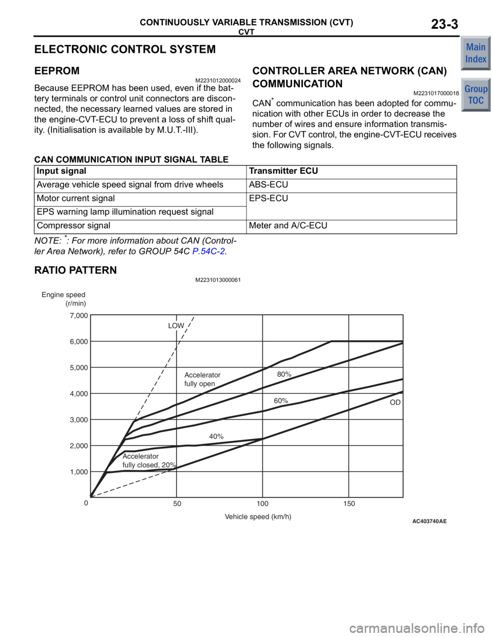
RATIO PATTERN
M2231013000061
AC403740
AE
Engine speed
(r/min)
Vehicle speed (km/h)
0
100 150
50
1,000 2,000 4,000
3,000 5,000
7,000
6,000
OD
LOW
Accelerator
fully closed, 20% 40%
Accelerator
fully open
60%80%
TRANSMISSION CONTROL
CONTINUOUSLY VARIABLE TRANSMISSION (CVT)23-6
TRANSMISSION CONTROL
GENERAL INFORMATIONM2232000100447
•A smart shift type selector lever has been
adopted in order to facilitate walkthrough
between the seats.
•A gun grip type selector lever knob has been
adopted for better operation and easier visual
recognition of the switches arranged in the centre
panel.
•The selector lever assembly has been a single
unit made by aluminium die casting for better
accuracy and fewer parts, resulting in the light
-
weight and compact structure.
•The selector lever has been designed to be com-
pact and appropriately configured not to interfere
with the energy absorbing mechanism on the
steering column upon impact of the vehicle.
•In order to prevent abrupt start by erroneous
operation of selector lever, a CVT erroneous
operation prevention mechanism (the shiftlock
mechanism and key interlock mechanism) has
been adopted.
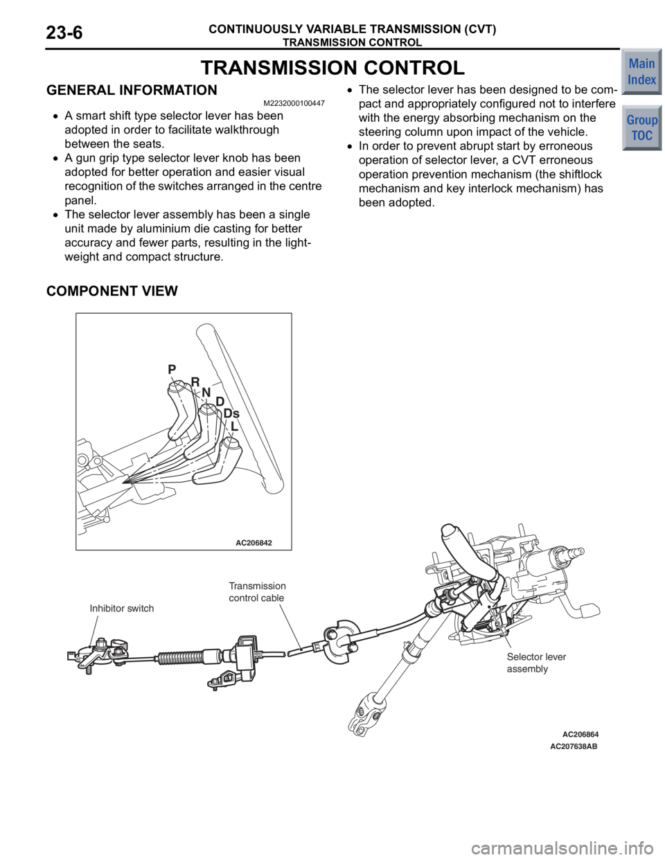
COMPONENT VIEW
AC206842
AC206864
AC207638
AB
P R
ND
Ds
L
Inhibitor switch Transmission
control cable
Selector lever
assembly