Tyre MITSUBISHI COLT 2006 Service Repair Manual
[x] Cancel search | Manufacturer: MITSUBISHI, Model Year: 2006, Model line: COLT, Model: MITSUBISHI COLT 2006Pages: 364, PDF Size: 11.65 MB
Page 16 of 364

BUMPER
EXTERIOR51-4
BUMPER
M2510002000751
FRONT BUMPER CONSTRUCTION DIAGRAM
AC402884AD
Air guide panel (RH)
Air guide panel (LH)
Air guide panel
•The front b u mpe r has overh ung at the right an d
le
f t corners to suppre s s the airflow to the tyres
and
smo o then t he airf low from the bumper to th e
ve
hicle sides.•
AC601475
Front bumper assembly
AB
Overfender construction
The air g u ide p a n e ls have been inst a lled behind
th
e fr on t b u mp er to impro v e t h e co olin g ef ficie n cy
of t
he radiator .
•The front b u mpe r emp hasizes the light ima ge in
fron
t appea rance.•Overfender const r uction from the f r ont bu mper t o
the
wh eel a r ch o f fende r appea ls the sporty and
robu
st whee lin g.< RALLIAR T V e rsion - R>
Page 86 of 364
GENERAL INFORMATION
REAR SUSPENSION34-2
GENERAL INFORMATION
M2340000100825
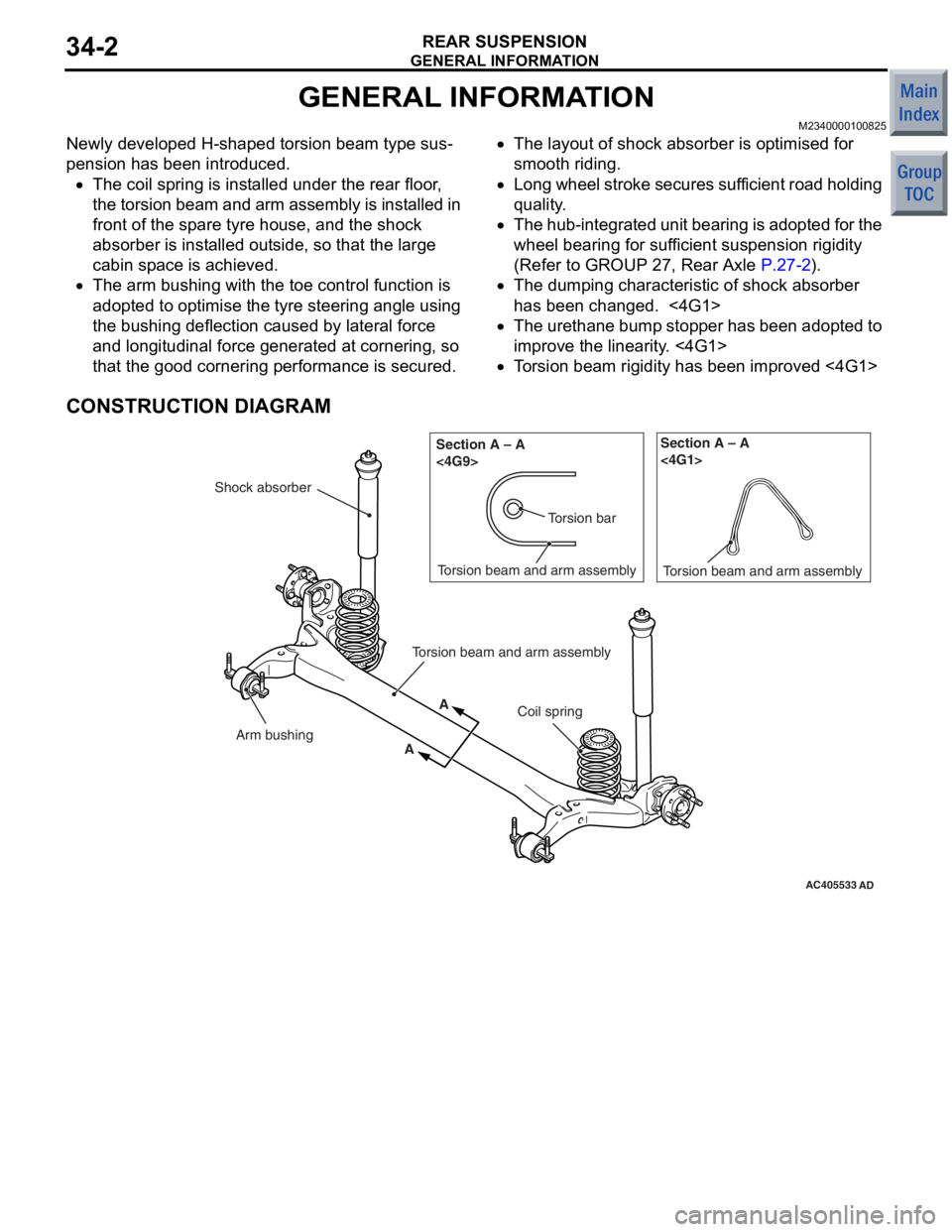
Newly developed H-shaped torsion beam type sus-
pension has been introduced.
•The coil spring is installed under the rear floor,
the torsion beam and arm assembly is installed in
front of the spare tyre house, and the shock
absorber is installed outside, so that the large
cabin space is achieved.
•The arm bushing with the toe control function is
adopted to optimise the tyre steering angle using
the bushing deflection caused by lateral force
and longitudinal force generated at cornering, so
that the good cornering performance is secured.
•The layout of shock absorber is optimised for
smooth riding.
•Long wheel stroke secures sufficient road holding
quality.
•The hub-integrated unit bearing is adopted for the
wheel bearing for sufficient suspension rigidity
(Refer to GROUP 27, Rear Axle
P.27-2).
•The dumping characteristic of shock absorber
has been changed. <4G1>
•The urethane bump stopper has been adopted to
improve the linearity. <4G1>
•Torsion beam rigidity has been improved <4G1>
CONSTRUCTION DIAGRAM
AC405533AD
Coil spring
Shock absorber
Torsion beam and arm assembly
Arm bushing
Torsion bar
Section A – A
<4G9>
A
A Torsion beam and arm assembly
Section A – A
<4G1>
Torsion beam and arm assembly
Page 87 of 364
GENERAL INFORMATION
REAR SUSPENSION34-3
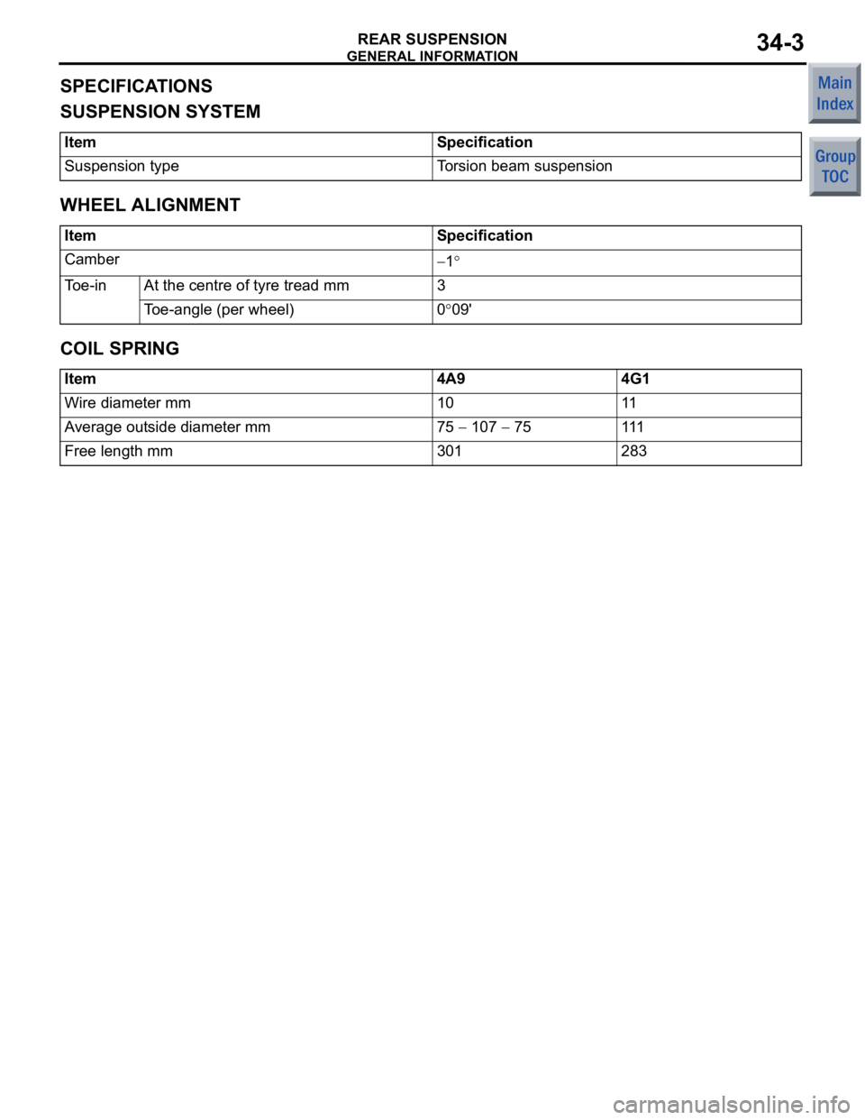
SPECIFICATIONS
SUSPENSION SYSTEM
ItemSpecification
Suspension typeTorsion beam suspension
WHEEL ALIGNMENT
ItemSpecification
Camber−1°
Toe-inAt the centre of tyre tread mm3
Toe-angle (per wheel)0°09'
COIL SPRING
Item4A94G1
Wire diameter mm1011
Average outside diameter mm75 − 107 − 75111
Free length mm301283
Page 227 of 364
GENERAL INFORMATION
FRONT SUSPENSION33-4
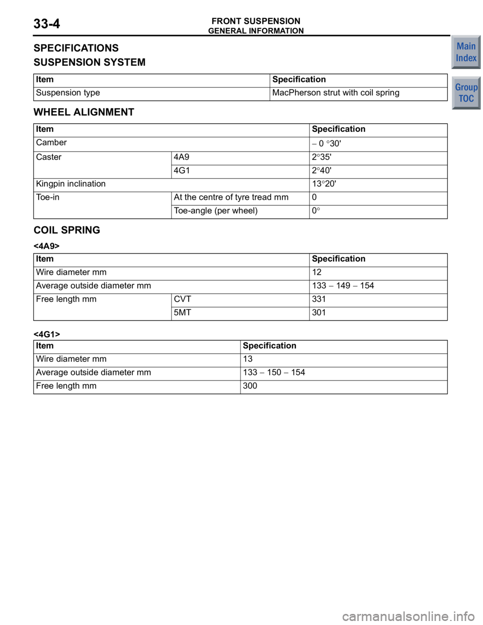
SPECIFICATIONS
SUSPENSION SYSTEM
ItemSpecification
Suspension typeMacPherson strut with coil spring
WHEEL ALIGNMENT
ItemSpecification
Camber − 0 °30'
Caster 4A92°35'
4G12°40'
Kingpin inclination 13°20'
Toe-inAt the centre of tyre tread mm0
Toe-angle (per wheel)0°
COIL SPRING
<4A9>
ItemSpecification
Wire diameter mm12
Average outside diameter mm133 − 149 − 154
Free length mmCVT331
5MT301
<4G1>
ItemSpecification
Wire diameter mm13
Average outside diameter mm133 − 150 − 154
Free length mm300
Page 228 of 364
GROUP 31
WHEEL AND TYRE
CONTENTS
GENERAL INFORMATION . . . . . . . .31-2
Page 229 of 364
GENERAL INFORMATION
WHEEL AND TYRE31-2
GENERAL INFORMATION
M2310000100800
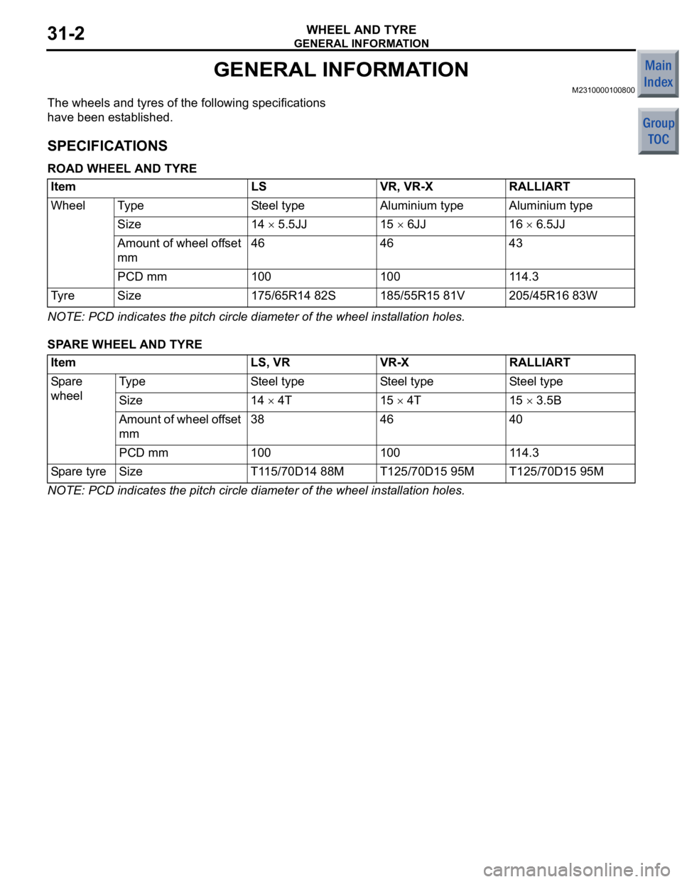
The wheels and tyres of the following specifications
have been established.
SPECIFICATIONS
ROAD WHEEL AND TYRE
ItemLSVR, VR-XRALLIART
WheelTy p eSteel typeAluminium typeAluminium type
Size14 × 5.5JJ15 × 6JJ16 × 6.5JJ
Amount of wheel offset
mm464643
PCD mm100100114.3
Ty r eSize175/65R14 82S185/55R15 81V205/45R16 83W
NOTE: PCD indicates the pitch circle diameter of the wheel installation holes.
SPARE WHEEL AND TYRE
ItemLS, VRVR-XRALLIART
Spare
wheelTy p eSteel typeSteel typeSteel type
Size14 × 4T15 × 4T15 × 3.5B
Amount of wheel offset
mm384640
PCD mm10010011 4 . 3
Spare tyreSizeT115/70D14 88MT125/70D15 95MT125/70D15 95M
NOTE: PCD indicates the pitch circle diameter of the wheel installation holes.