diagram MITSUBISHI COLT 2006 Service Repair Manual
[x] Cancel search | Manufacturer: MITSUBISHI, Model Year: 2006, Model line: COLT, Model: MITSUBISHI COLT 2006Pages: 364, PDF Size: 11.65 MB
Page 3 of 364
GENERAL INFORMATION
ANTI-SKID BRAKE SYSTEM (ABS)35B-3
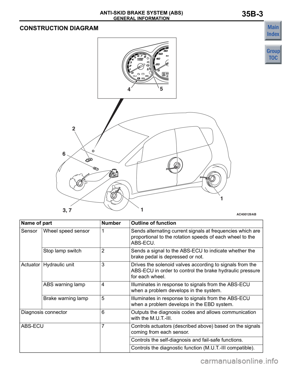
CONSTRUCTION DIAGRAM
AC400129AB1
2
3, 7 1
4
5
6
Name of partNumberOutline of function
SensorWheel speed sensor1Sends alternating current signals at frequencies which are
proportional to the rotation speeds of each wheel to the
ABS-ECU.
Stop lamp switch2Sends a signal to the ABS-ECU to indicate whether the
brake pedal is depressed or not.
ActuatorHydraulic unit3Drives the solenoid valves according to signals from the
ABS-ECU in order to control the brake hydraulic pressure
for each wheel.
ABS warning lamp4Illuminates in response to signals from the ABS-ECU
when a problem develops in the system.
Brake warning lamp5Illuminates in response to signals from the ABS-ECU
when a problem develops in the EBD system.
Diagnosis connector6Outputs the diagnosis codes and allows communication
with the M.U.T.-III.
ABS-ECU7Controls actuators (described above) based on the signals
coming from each sensor.
Controls the self-diagnosis and fail-safe functions.
Controls the diagnostic function (M.U.T.-III compatible).
Page 4 of 364
GENERAL INFORMATION
ANTI-SKID BRAKE SYSTEM (ABS)35B-4
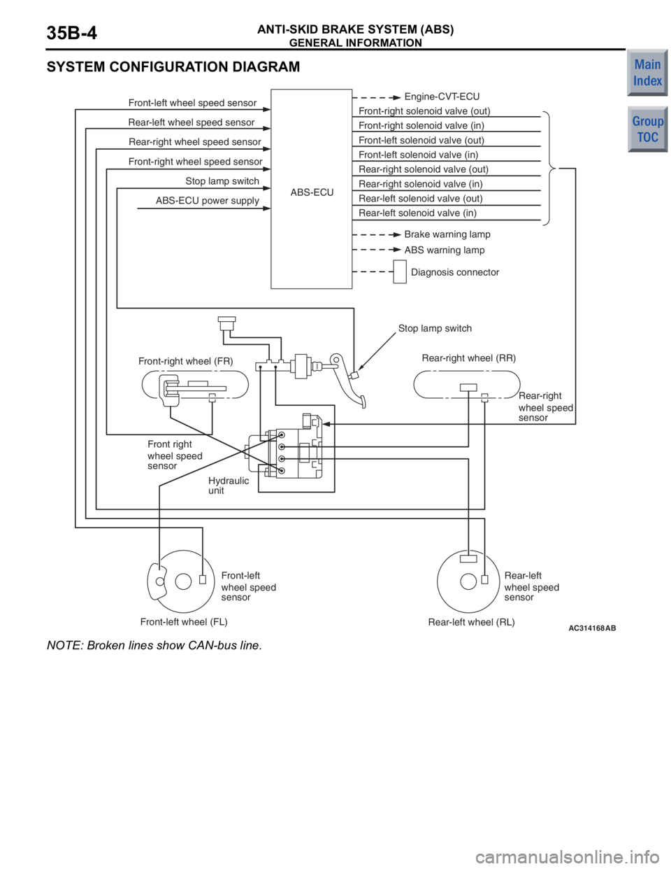
SYSTEM CONFIGURATION DIAGRAM
AC314168
Stop lamp switch
Front-right wheel speed sensor Rear-right wheel speed sensor
Rear-left wheel speed sensor Front-left wheel speed sensor
ABS-ECU power supply Engine-CVT-ECU
Front-right solenoid valve (out)
Front-right solenoid valve (in)
Front-left solenoid valve (out)
Front-left solenoid valve (in)
Rear-right solenoid valve (out)
Rear-right solenoid valve (in)
Rear-left solenoid valve (out)
Rear-left solenoid valve (in)
ABS-ECU
Hydraulic
unit Rear-right
wheel speed
sensor
Front right
wheel speed
sensor
Front-left
wheel speed
sensor Rear-left
wheel speed
sensor
Front-right wheel (FR)
Front-left wheel (FL) Rear-right wheel (RR)
Rear-left wheel (RL)
Stop lamp switch
AB
Brake warning lamp
ABS warning lamp
Diagnosis connector
NO TE: Broken lines show CAN-bus lin e.
Page 5 of 364
GENERAL INFORMATION
ANTI-SKID BRAKE SYSTEM (ABS)35B-5
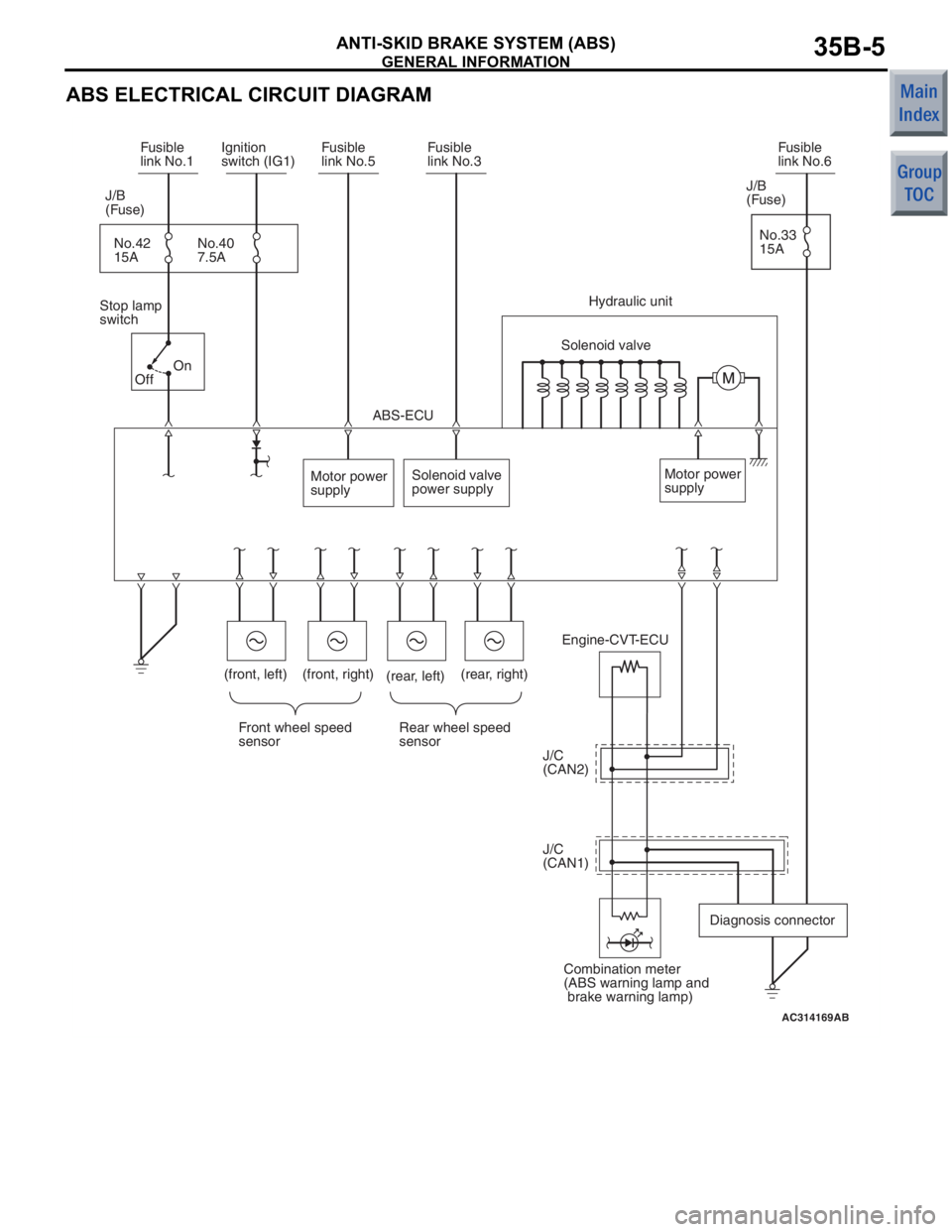
ABS ELECTRICAL CIRCUIT DIAGRAM
AC314169
Engine-CVT-ECU
Front wheel speed
sensor Rear wheel speed
sensor
Motor power
supply
Solenoid valve
power supply
ABS-ECU
Motor power
supply
Solenoid valve
Hydraulic unit
Stop lamp
switch J/B
(Fuse)
No.42
15A No.40
7.5A
Fusible
link No.1
Ignition
switch (IG1) Fusible
link No.5 Fusible
link No.3
J/B
(Fuse)
No.33
15A Fusible
link No.6
J/C
(CAN2)
J/C
(CAN1) Diagnosis connector
Combination meter
(ABS warning lamp and
brake warning lamp)
AB
(rear, right)
(front, right)
(front, left)
(rear, left)
On
Off
Page 15 of 364
RADIATOR GRILLE
EXTERIOR51-3
RADIATOR GRILLE
M2510001000468
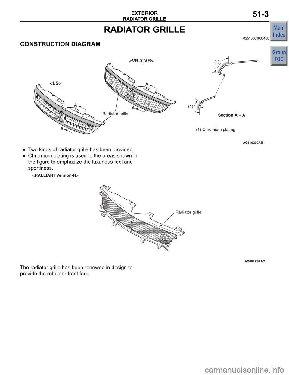
CONSTRUCTION DIAGRAM
AC510290AB
Section A – A
Radiator grille
(1) Chromium plating
(1) (1)
A
A
AA
•T
w o kinds of ra diato r grille ha s be en provide d .
•
AC601298AC
Radiator grille
Chromium plat ing is u s ed t o the a r eas shown in
the
figure to emphasize the luxu rious feel and
sp
ortin e ss .
The radi ator g r ille has been renewed in de sig n to
provide the
robuster fron t face.
Page 16 of 364

BUMPER
EXTERIOR51-4
BUMPER
M2510002000751
FRONT BUMPER CONSTRUCTION DIAGRAM
AC402884AD
Air guide panel (RH)
Air guide panel (LH)
Air guide panel
•The front b u mpe r has overh ung at the right an d
le
f t corners to suppre s s the airflow to the tyres
and
smo o then t he airf low from the bumper to th e
ve
hicle sides.•
AC601475
Front bumper assembly
AB
Overfender construction
The air g u ide p a n e ls have been inst a lled behind
th
e fr on t b u mp er to impro v e t h e co olin g ef ficie n cy
of t
he radiator .
•The front b u mpe r emp hasizes the light ima ge in
fron
t appea rance.•Overfender const r uction from the f r ont bu mper t o
the
wh eel a r ch o f fende r appea ls the sporty and
robu
st whee lin g.< RALLIAR T V e rsion - R>
Page 17 of 364
BUMPER
EXTERIOR51-5
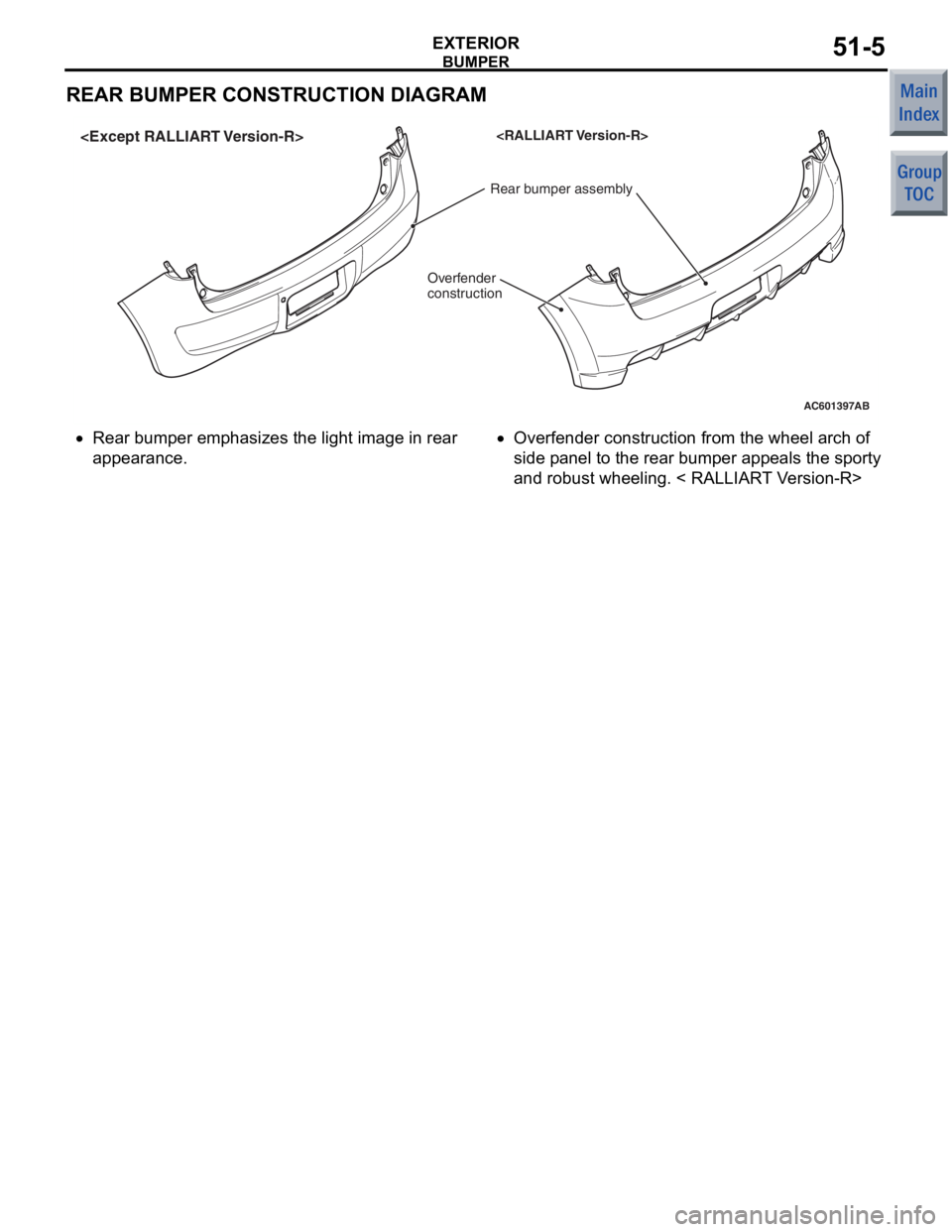
REAR BUMPER CONSTRUCTION DIAGRAM
AC601397
Rear bumper assembly
AB
Overfender
construction
•Rear b
u mpe r emp hasizes the ligh t image in rear
app
earance.•Overfe nder construction from the wh eel a r ch o f
side p
ane l to t he rear bump e r appe als the sporty
and
robust wheeling. < RAL L IAR T V e rsion-R>
Page 19 of 364
AERO PARTS
EXTERIOR51-7
AERO PARTS
M2510003000583
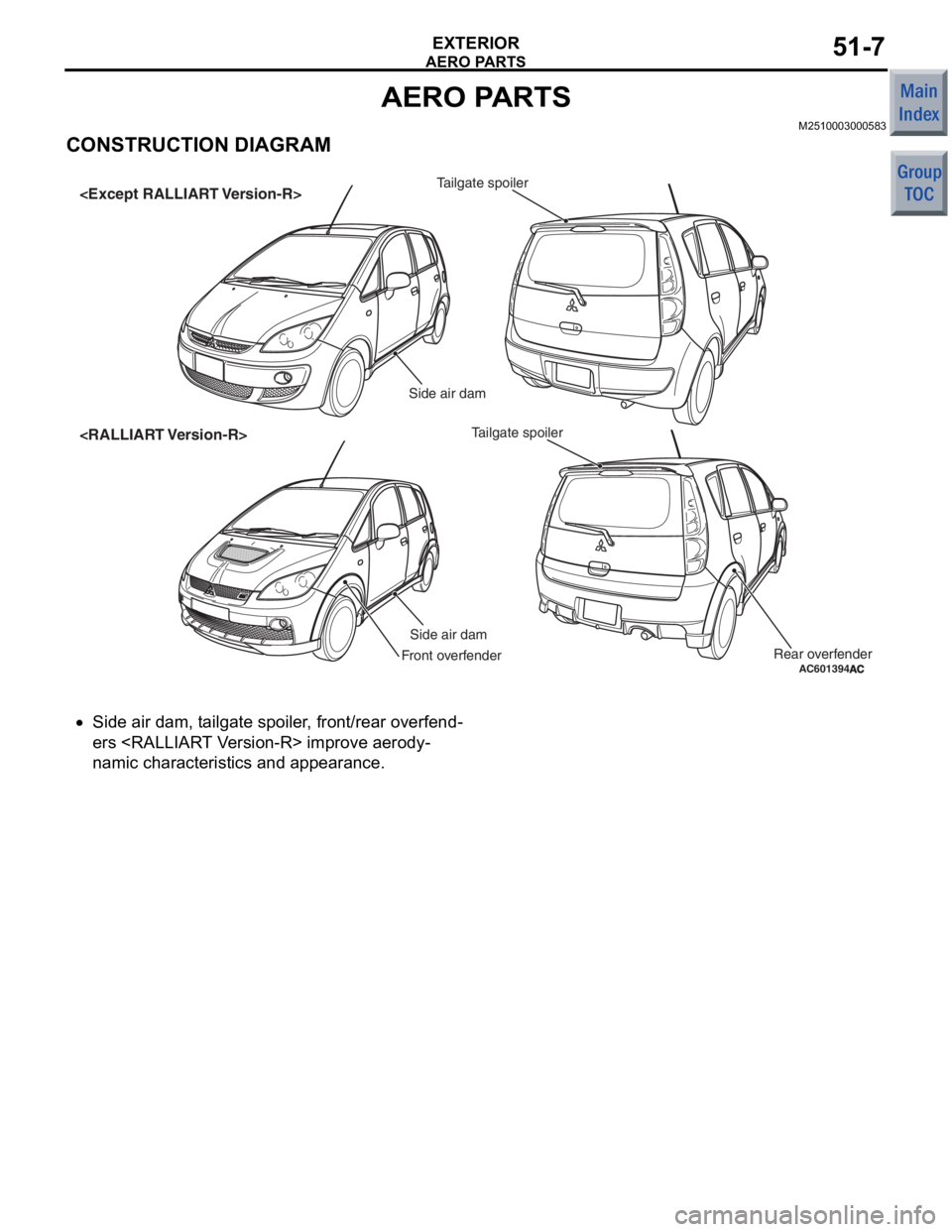
CONSTRUCTION DIAGRAM
AC601394
Side air damTailgate spoiler
Side air dam
Tailgate spoiler
Front overfenderRear overfenderA
C
•Side air d a m, t a ilgate spo iler , front/re a r overfend-
ers
namic char acte ristics and a ppeara n ce.
Page 21 of 364
WIPER AND WASHER
EXTERIOR51-9
WIPER AND WASHER
WINDSHIELD WIPER AND WASHERM2510007000358
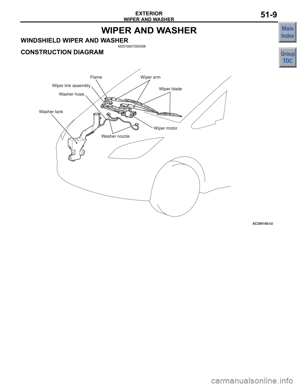
CONSTRUCTION DIAGRAM
AC206160AB
Washer nozzle
Washer hose
Wiper motor
Wiper arm
Wiper blade
Wiper link assembly
Washer tank Flame
Page 23 of 364
WIPER AND WASHER
EXTERIOR51-11
REAR WIPER AND WASHER
M2510008000403
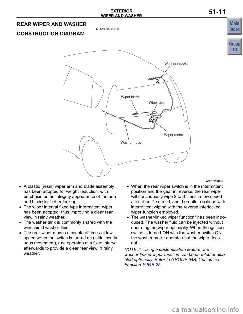
CONSTRUCTION DIAGRAM
AC510298AB
Washer hoseWasher nozzle
Wiper motor
Wiper arm
Wiper blade
•A plastic (resin) wiper arm and
blade assemb ly
has bee
n adop ted for we ight re duct i on, with
emphasis on
an integ r ity appea rance of the arm
and
blad e for be tter looking.
•The wiper interval fixed type intermitte nt wiper
has bee
n adop ted, th us improving a clear re ar
view in
rainy weather .
•The wa sher t a n k is co mmonly sha r ed with the
wind
shield washer fluid.
•The rear wipe r moves a co uple of times at low
sp
eed whe n the switch is turned on (in i tia l contin
-
uous moveme nt), and opera t es at a fixe d interval
af
terwards to pr ovid e a clear rear view in rainy
weathe
r .
•When the re ar wiper switch is in the in termittent
position an
d the g ear in reve rse, th e rear wiper
will co
ntinu ously wipe 2 to 3 times in low spee d
af
ter about 1 second, and thereaf ter contin ue with
in
termittent wiping with the reve rse interlocked
wipe
r function employe d .
•The washer-linke d wiper function * has b een int r o-
duced. The wash er flu i d can be injected withou t
ope
rating the wip e r optionally . Wh en the ignition
switch is tu
rned ON with th e washe r switch ON,
the
wa sher moto r operate s bu t the wiper doe s
not
.
NO TE: *: Using a cust omisation fea t ure, th e
wa
sher
-lin ked wiper fun c tio n ca n be e nable d or disa
-
bled optio nally . Refer to GROUP 54 B, Cu stomise
Funct
i on
P.54B-25.
Page 24 of 364
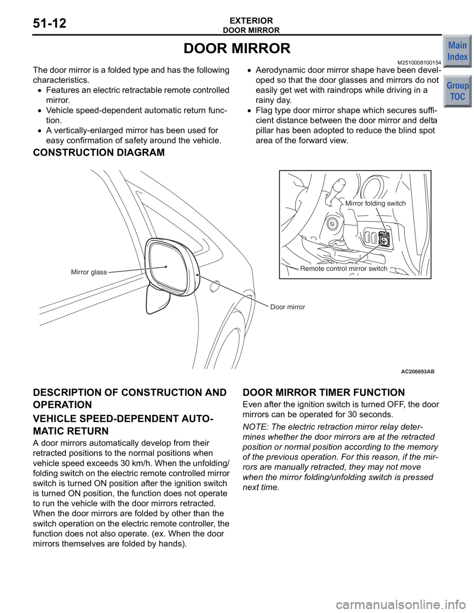
DOOR MIRROR
EXTERIOR51-12
DOOR MIRROR
M2510008100154
The door mirror is a folded type and has the following
characteristics.
•Features an electric retractable remote controlled
mirror.
•Vehicle speed-dependent automatic return func-
tion.
•A vertically-enlarged mirror has been used for
easy confirmation of safety around the vehicle.
•Aerodynamic door mirror shape have been devel-
oped so that the door glasses and mirrors do not
easily get wet with raindrops while driving in a
rainy day.
•Flag type door mirror shape which secures suffi-
cient distance between the door mirror and delta
pillar has been adopted to reduce the blind spot
area of the forward view.
CONSTRUCTION DIAGRAM
AC206693AB
Door mirror
Mirror glass
Remote control mirror switchMirror folding switch
DESCRIPTION OF CONSTRUCTION AND
OPERA
T ION
VEHICLE SPEED-DEPENDENT AUT O-
MATIC RETURN
A d oor mirrors automatically d e velop fro m the i r
retract
ed positions to the norma l positions wh en
ve
h i cle spe e d exce ed s 3 0 km/ h . Wh en t h e un fo ldin g/
fold
in g switch on t h e e l ectr ic re mo te co nt ro lled mirr or
switch is turned
ON po sition af ter the ig nition switch
is tu
rned ON positio n, the funct i on d oes n o t ope rate
to run th
e ve hicle with the do or mirrors retracted.
When th
e door mirro rs are fold ed by other t han th e
s
w itc h ope rat i on o n th e ele c t r i c rem o t e c o n t rol l er , th e
funct
i on d oes n o t also op erate. (ex. W hen the door
mirro
rs the m selve s are fold ed by hands).
DOOR MIRROR TIMER FUNCTION
Even after the ignition swit ch is turned OFF , the d oor
mirro
rs can be operate d for 30 seconds.
NOTE: The electric retraction mirror rela y de ter-
mine s whet her the door mirrors are a t the re tracte d
position
or normal p o sition accordin g to the memory
of the p
r evious operation. F o r this reason, if the mir
-
rors ar e man ually ret r acte d, they ma y not move
wh
en the mirro r fold ing/u n fold ing switch is pressed
next time
.