service belt MITSUBISHI COLT 2006 Service Repair Manual
[x] Cancel search | Manufacturer: MITSUBISHI, Model Year: 2006, Model line: COLT, Model: MITSUBISHI COLT 2006Pages: 364, PDF Size: 11.65 MB
Page 181 of 364

COMBINATION METER
CHASSIS ELECTRICAL54A-10
COMBINATION METER
M2540005000894
The combination meter features large, clearly visible
analogue indicators. The meter has the speedometer
in the middle, the coolant temperature gauge at
upper right, the fuel gauge at lower right, and the
tachometer at left so that drivers can easily distin
-
guish the information from the meters. The combina-
tion meter offers the following advantages.
•The combination meter is used for air conditioner
and meter drive control to integrate ECU.
•CAN communication is used for more reliable
transmission of all gauge data and indicator lamp
input signals, such as vehicle speed, engine
RPM, and coolant temperature. For further
details on CAN, refer to GROUP 54C, CAN
P.54C-2. The signals that the combination meter
uses are described in the CAN communications
input signals table
.
•Several diagnosis functions such as the diagno-
sis code memory and actuator tests are prepared
in order to improve serviceability.
•For a brighter display at night and for a longer
useful life, all indicator lamps, warning lamps, and
illumination bulbs use LEDs.
•The indicators for the speedometer, fuel gauge,
and other gauges are driven by a stepping motor.
For further details, consult the stepping motor
section
.
•The electronic speedometer operates by receiv-
ing vehicle speed signals sent by the
engine-ECU
via the CAN.
•A large and clear LCD type odo-tripmeter is pro-
vided. The odometer continuously displays val-
ues while the tripmeter adopts a twin-trip (trip A,
trip B) function which is switched by a reset but
-
ton. In addition, clock function is incorporated.
•A fog lamp indicator lamp is provided to let the
driver know that the fog lamp is on.
•A seat belt warning lamp is installed to encourage
the driver to fasten the seat belt.
•The high-contrast meter is adopted. When the
ignition is turned ON, such as the needles and
face display are illuminated with fade-in lighting
by the LED light source.
•To further accentuate the high-contrast lighting,
the light of the high-contrast meter fades in and
fades out when the light is turned on and off
respectively.
•With the auto illumination function incorporated in
the high-contrast meter, a two-stage switching of
daytime (non-dimming) and nighttime (dimming)
is achieved. Also, the brightness can be adjusted
using the illumination control knob.
•A tail lamp indicator lamp is installed which
informs the lighting status of the tail lamps to the
driver.
Page 214 of 364

TECHNICAL FEATURES
GENERAL00-29
IMPROVED SERVICEABILITY
•Employment of an automatic hydraulic timing belt
tensioner offers timing belt reliability, reduced
operating noise, and better serviceability. <4G1>
•Wiring harness section of the crank angle sensor
has been moulded integrally with the timing belt
cover, improving serviceability and reliability.
<4G1>
•Due to the adoption of the timing chain and the
timing chain tensioner, maintenance-free and reli
-
ability have been improved. <4A9>
•Since adoption of unvolatile memory (EEPROM*)
helps the learned value not to be initialised when
the battery terminal or connector of the control
unit is disconnected, maintainability can be
improved.
NOTE: *EEPROM: Electrical Erasable Programma-
ble ROM (information to be memorised can be
electronically written into and erased from ROM)
•Since the adoption of electric power steering
makes hydraulic pipes and oil pumps unneces
-
sary, maintainability can be improved.
•Employment of operative A/C piping layout and
refrigerant leak detection system enhances serv
-
iceability.
Page 297 of 364
GENERAL INFORMATION
SUPPLEMENTAL RESTRAINT SYSTEM (SRS)52B-5
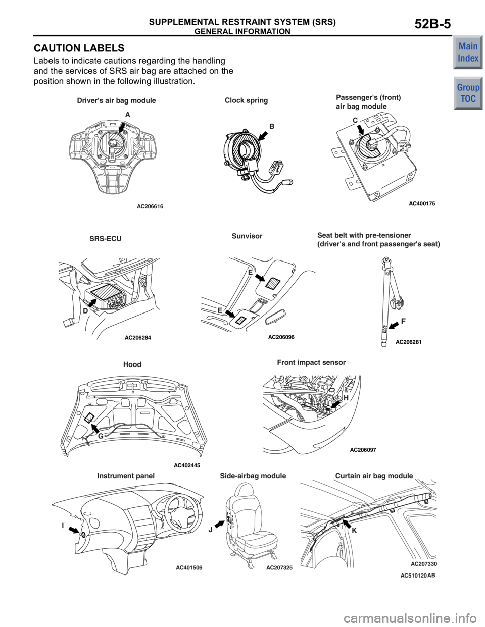
CAUTION LABELS
Labels to indicate cautions regarding the handling
and the services of SRS air bag are attached on the
position shown in the following illustration.
AC510120
AC206616
AC206284
AC206096AC206281
AC206097
AC400175
AC401506AC207325AC207330
AC402445
AB
A Clock spring
B
Driver's air bag module
Passenger's (front)
air bag module
SRS-ECUSunvisor
F
Seat belt with pre-tensioner
(driver's and front passenger's seat)
Hood
G Front impact sensor
IJK
Curtain air bag module
Side-airbag module
Instrument panel C
D EE
H
Page 298 of 364

GENERAL INFORMATION
SUPPLEMENTAL RESTRAINT SYSTEM (SRS)52B-6
Label contents
ADANGER FLAMMABLE MATERIAL
TO PREVENT PERSONAL INJURY. DO NOT DISMANTLE, INCINERATE, OR BRING
INTO CONTACT WITH ELECTRICITY. STORE BELOW 200
°F (93°C). READ SERVICE
MANUAL FOR DETAIL.
BCAUTION: SRS CLOCK SPRING
THIS IS NOT A REPAIRABLE PART. IF DEFECTIVE, REPLACE ENTIRE UNIT
ACCORDING TO THE SERVICE MANUAL INSTRUCTIONS. TO RE-CENTRE: ROTATE
CLOCKWISE UNTIL TIGHT. THEN ROTATE IN OPPOSITE DIRECTION ROUGHLY 3
3/4 TURNS AND ALIGN ARROWS >><<.
CDANGER FLAMMABLE MATERIAL
TO PREVENT PERSONAL INJURY. DO NOT DISMANTLE, INCINERATE, OR BRING
INTO CONTACT WITH ELECTRICITY. STORE BELOW 200
°F (93°C). READ SERVICE
MANUAL FOR DETAIL.
DCAUTION:
DO NOT DISASSEMBLE OR DROP. IF DEFECT REFER TO SERVICE MANUAL.
E
WARNING
•DEATH OR SERIOUS INJURY can occur.
•ALWAYS use SEAT BELT and CHILD SEAT.
•DO NOT sit or lean unnecessarily close to the air bag.
•DO NOT place or install any objects over the air bag or between the air bag and
yourself.
WARNING
•DEATH OR SERIOUS INJURY can occur
•DO NOT place rear-facing child seat on this seat with airbag.
FDANGER: SEAT BELT PRETENSIONER
DO NOT DISASSEMBLE OR IMPACT
REFER TO SERVICE MANUAL FOR INSTRUCTIONS, HANDLING, STORAGE AND
DISPOSAL PROCEDURES.
GWARNING
THIS VEHICLE HAS AN AIR BAG SYSTEM. REFER TO SERVICE MANUAL BEFORE
SERVICING OR DISASSEMBLING UNDERHOOD COMPONENTS. READ THE "SRS"
SECTION OF MANUAL FOR IMPORTANT INSTRUCTIONS. IMPROPER SERVICE
PROCEDURES CAN RESULT IN THE AIR BAG FIRING OR BECOMING
INOPERATIVE, POSSIBLY LEADING TO INJURY.
HCAUTION:
DO NOT DISASSEMBLE OR DROP.
Page 305 of 364
SYSTEM CONSTRUCTION
SUPPLEMENTAL RESTRAINT SYSTEM (SRS)52B-13
SEAT BELT WITH PRE-TENSIONER
M2521008000195
AC208129
AC207230AC207336ACPipe Gear
Ball Spool
Gas generator
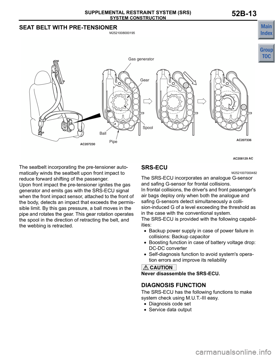
The seatbelt incorpo
r ating the pre - tensioner auto-
matically winds the seatbelt upo n front imp a ct to
reduce forward shif
ting of th e p a ssenge r .
Upon front imp a ct the pre-ten s ion e r ig nites the g a s
generat
or and emit s gas with the SRS-ECU signal
whe
n t he front imp a ct sen s or , att a ched to the front of
the bo
dy , dete c t s a n imp a ct t hat excee d s t he per mis
-
sible limit. By this g a s p r essure, a ball moves in the
p
i p e and rot a tes the g ear . This gear rot a tion operat es
the spool
in the directio n of ret r acting the belt, and
the webbing is retra
c ted .
SRS-ECU
M25210070 0048 2
The SRS-ECU incorp orates an an alog ue G-sensor
and safing
G-sensor for fro n t a l collisions.
In frontal collision s , the dr iver's an d front p a ssenge r's
air ba
gs d eploy only when both t he ana logue and
safing G-sensors detect
simult a neously a co lli
-
sion -indu ced G of a le vel exceed ing the thresh old as
in the
case with the conve n tion al system.
The SRS-ECU is prov ide d with t he followin g cap a b i l-
ities:
•Backup p o wer su pply in case of po we r failure in
c
o lli si ons: Ba cku p ca p a cito r
•Boosting function in ca se of battery volt a ge drop :
DC-DC converter
•Self-diag nosis fu nction to a v oid syste m 's opera-
tion errors and imp r ove it s reliabilit y
CAUTION
Never disassemble the SRS-ECU.
DIAGNOSIS FUNCTION
The SRS-ECU has the following functions to make
system check using M.U.T.-III easy.
•Diagnosis code set
•Service data output