Power steering MITSUBISHI DIAMANTE 1900 Repair Manual
[x] Cancel search | Manufacturer: MITSUBISHI, Model Year: 1900, Model line: DIAMANTE, Model: MITSUBISHI DIAMANTE 1900Pages: 408, PDF Size: 71.03 MB
Page 10 of 408
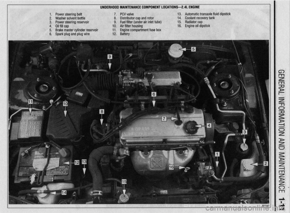
UNDERHDDD MAINTENANCE COMPONENT LOCATIONS-2AL ENGINE
II
1. Power steering belt 7. PCV valve
2. Washer solvent bottle 8. Distributor cap and rotor
3. Power steering reservoir 9. Fuel filter (under air inlet tube)
4. Oil fill cap 10. Air filter housing
5. Brake master cylinder reservoir 11. Engine compartment fuse box
6. Spark plug and plug wire 12. Battery 13. Automatic transaxle fluid dipstick
14. Coolant recovery tank
15. Radiator cap
16. Engine oil dipstick
Page 11 of 408
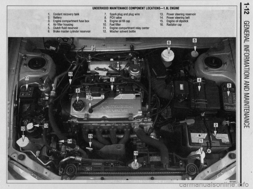
UNDERHOOD MAINTENANCE COMPONENT LOCATIONS-l .8L ENGINE
1. Coolant recovery tank
2. Battery
3. Engine compartment fuse box
4. Air filter housing
5. Clutch fluid reservoir
6. Brake master cylinder reservoir 7. Spark plug and plug wire
8. PCV valve
9. Engine oil fill cap
10. Fuel filter
11. Engine compartment relay center
12. Washer solvent bottle 13. Power steering reservoir
14. Power steering belt
15. Engine oil dipstick
16. Radiator cap
Page 17 of 408
l
1-18 GENERALINFORMATIONAND MAINTENANCE
the clamps and remove the cables, negative cable
first. On batteries with posts on top, the use of a
puller specially made for this purpose is recom-
mended. These are inexoensive and available in most alternator or turn the adjusting bolt to adjust belt ten-
sion. Once the desired value is reached, secure the
bolt or locknut and recheck tension.
d”t” lJdlL> X”lt;>. 31°C LtXlllllldl lJdllt2)’ MLJIC, dlt’ X- cured with a small bolt. ST& I REMOVAL &INSTALLATION
Clean the cable clamps and the battery terminal I
with a wire brush, until all corrosion, grease, etc., is
removed and the metal is shinv. It is esneciallv imnnr-
tant to c
knife is useful nere), since a smart
material or oxidation there will pre Clean the cable clamps and the battery terminal
with a wire brush, until all corrosion, grease, etc., is
removed and the metal is shiny. It is especially impor-
tant to clean the inside of the clamp thoroughly (an old
knife is useful here), since a small deposit of foreign
material or oxidation there will prevent a sound electri-
cal connection and inhibit either starting or charging.
Special tools are available for cleaning these parts,
one type for conventional top post batteries and an-
other type for side terminal batteries. It is also a good
idea to apply some dielectric grease to the terminal, as
this will aid in the prevention of corrosion,
After the clamps and terminals are clean, reinstall
the cables, negative cable last; DO NOT hammer the
clamps onto battery posts. Tighten the clamps se-
curely, but do not distort them. Give the clamps and
terminals a thin external coating of grease after in-
stallation, to retard corrosion.
Check the cables at the same time that the terminals
are cleaned. If the cable insulation is cracked or bro-
ken, or if the ends are frayed, the cable should be re-
placed with a new cable of the same length and gauge.
CHARGING
the cables, negative cable last; DO NOT hammer the
curely, but do not distort them. Give the clamps and
terminals a thin external coating of grease after in-
stallation, to retard corrosion.
Check the cables at the same time that the terminals
are cleaned. If the cable insulation is cracked or bro-
ken, or if the ends are frayed, the cable should be re-
placed with a new cable of the same length and aauae.
CHARGING
Fig. 62 mere are typically 3 types of ac-
cessory drive belts found on vehicles today 1. Loosen the alternator support nut.
2. Loosen the adjuster lock bolt.
3. Rotate the adjuster bolt counter clockwise to
I .I , . . . * . .
I Tn i”et*ll* Fig. 62 There are typically 3 types of ac-
Fig. 64 Deep cracks in this belt will cause
flex, building up heat that will eventually 11, 1.8L, 2.OL and 2.4L Engines
cal connection and inhibit either starting or charging.
Special tools are available for cleaning these parts,
one type for conventional top post batteries and an-
other type for side terminal batterin, I+ if QI@* 3 nnnd
idea to apply some dielectric grr
this will aid in the prevention of ,,vIIuaIUII.
After the clamps and terminals are clean, reinstall 1.5L, 1.6
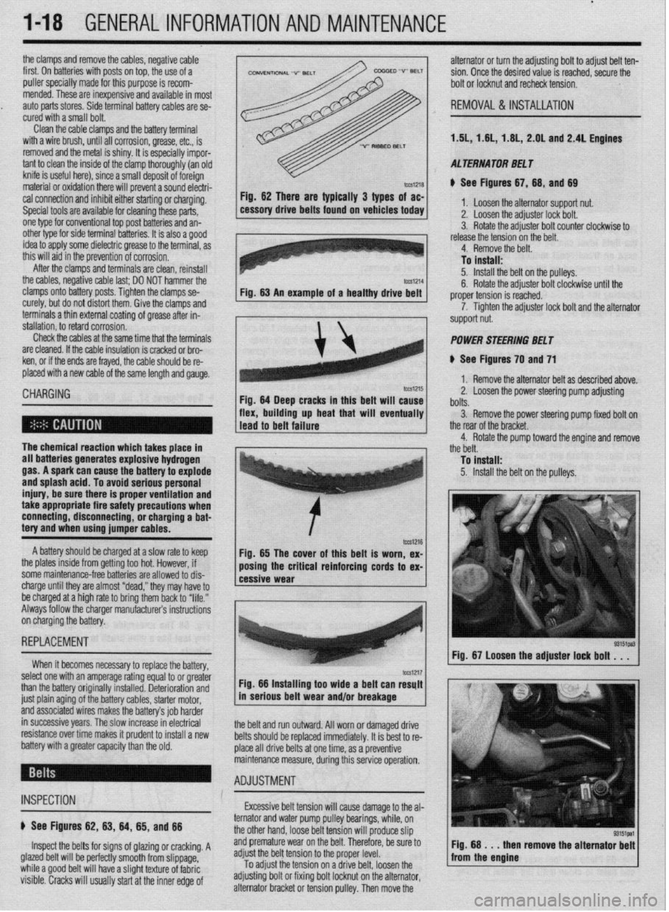
AL TERNA TOR BE1 T
e See Figures 67,68, and 69
1. Loosen the alternator support nut.
2. Loosen the adjuster lock bolt.
3. Rotate the adjuster bolt counter clockwise to
release the tension on the belt.
4. Remove the belt.
To install:
5. Install the belt on the pulleys.
6. Rotate the adjuster bolt clockwise until the
proper tension is reached.
7. Tighten the adjuster lock bolt and the alternator
support nut.
POWER STEERING BELT
8 See Figures 70 and 71
1. Remove the alternator belt as described above.
2. Loosen the power steering pump adjusting
bolts.
3. Remove the power steering oumo fixed bolt on
R Rntatn the cxiillrtm hnit A&+,& until the r -r- .- .- ._.. ._ .______
7. Tighten the adjuster lock bolt and the alternator
support nut.
POWER STEERING BELT
1 ..“‘.I ““..Y...Y up II”“. ..IU. ..m.*
1 lead to belt failure V.
I
I
The chemical reaction which takes place in - 1 the rear of the bracket.
4. Rotate the pump toward the engine and remove
the belt.
all batteries generates explosive hydrogen
gas. A spark can cause the battery to explode
and splash acid. To avoid serious personal
injury, be sure there is proper ventilation and
take appropriate fire safety precautions when
connecting, disconnecting, or charging a bat-
tery and when using jumper cables. To fnstall:
5. Install the belt on the pulleys.
A battery should be charged at a slow rate to keep
the plates inside from getting too hot. However, if
some maintenance-free batteries are allowed to dis-
charge until they are almost “dead,” they may have to
be charged at a high rate to bring them back to “life.”
Always follow the charger manufacturers instructions
on charging the battery. 85 The cover of this belt ex-
Fig. is worn,
REPLACEMENT
When it becomes necessary to reolace thn haeoN
‘” yyL’“‘J’ I or oreMer
select one with an amperage rating equal tc .
a ----
than the battery originally installed. Deterioration and
just plain aging of the battery cables, starter motor,
and associated wires makes the battery’s job harder
in successive years. The slow increase in electrical
resistance over time makes it prudent to install a new
battery with a greater capacity than the old. 1 Fig. 67 Loosen the adjuster lock bolt . . .
I ‘-
I -. -_ tm1217 Fig. 66 Installing too wide a belt can resylt
in serious belt wear and/or breakage
the belt and run outward. All worn or damaged drive
belts should be replaced immediately. It is best to re-
place all drive belts at one time, as a preventive
uring this service operation. maintenance measure, d
- ADJUSTMENT : *
INSPECTION Excessive belt tension will cause damage to the al-
e See Figures 62, 83, 64, 65, and 88
Inspect the belts for signs of glazing or cracking. A
glazed belt will be perfectly smooth from slippage,
while a good belt will have a slight texture of fabric
visible. Cracks will usually start at the inner edge of pulley bearings, while, on
It tension will
Droduce slin ternator and water pump
the other hand, loose be
r ------ r
and premature wear on the belt. Therefore, be sure to
adjust the belt tension to the proper level.
To
adjust the tension ’ ’ ’ ” ’ ‘* adjusting bolt or fixing b
alternator bracket or tens on a onve Den. loosen me I Fig. 68 . . . then
from the engine remove the alternator
bolt locknut on the alternator,
iion pulley. Then move the
Page 18 of 408
GENERAL INFORMATION AND MAlNTENANdE l-19
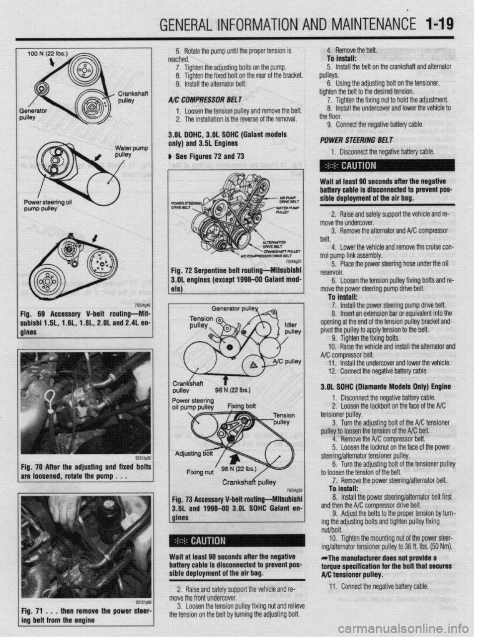
792UQ4 Fig. 69 Accessory V-belt routing-Mii
subishf 1.6L, 1.6L,-1.6L, 2.OL and 2.4L en
gines
33151PM Fig. 70 After the adjusting and fixed bolt!
are loosened, rotate the pump . . .
/ F$71t immtl$mm&a the power ::: 6. Rotate the pump until the proper tension is
reached.
7. Tighten the adjusting bolts on the pump.
8. Tighten the fixed bolt on the rear of the bracket.
9. Install the alternator belt.
A/r: COMPRESSOIl BEL f
1. Loosen the tension oullev and remove the belt.
2. The installation is the reverse of the removal.
.3.gL DGHC, 3.OL SOHC (Gaiant models
only) and 3.5L Engines 4. Remove the belt.
To install:
5. Install the belt on the crankshaft and alternator
pulleys.
6. Using the adjusting bolt on the tensioner,
tighten the belt to the desired tension.
7. Tighten the fixing nut to hold the adjustment.
8. Install the undercover and lower the vehicle to
_,
the tloor.
9. Connect the negative battery cable.
POWER SliEERlNG BEL f
6 See Figures 72 and 73 1. Disconnect the neaative batteN cah+P
-I
Wait at least 60 seconds after the negative
battery cable is disconnected to prevent poS-
sibie deployment of the air bag.
2. Raise and safely support the vehicle and re-
mob re the undercover.
3. Remove the alternator and NC compressor
belt.
4. Lower the vehicle and remove the cruise con-
trol oumn link iW%mblV. 79244Q.37
-- I-- r ---- - _I
Fig. 72 Serpentine belt routing-Mitsubishi 5. Place the power steering hose under the oil
reservoir.
3.OL engines (except 1696-00 Galant mod-
6.
Loosen the tension pulley fixing bolts and re-
els)
Generator pulP
1 move the power steering pump drive belt.
To install:
1 7. install the Dower steerina oumu r+r+v~ hp++
8. Insert an extension bar &eoufvaik;;t”f;;id‘he
opening at the end of the tension pulley bracket and
pivot the pulley to apply tension to the belt.
9. Tighten the fixing bolts.
10. Raise the vehicle and install the alternator and
compressor belt.
Il. Install the undercover and lower +hfi vph+r+p
.I,., .VII.“.Y.
12. Connect the negative battery cable.
I 3.OL SGHC (Diamante Models Onivl Enotne
I ,r ” 1. Disconnect the negative battery cable.
2.’ Loosen the lockbolt on the face nf the A/C _ __.- tensioner pulley.
3
Turn the adiustina bolt of the A/C +fincrnner
pulley to loosen the tension of the A/C belt.
4. Remove the A/C compressor belt.
5.
Loosen the locknut on the face of the power
to loosen the tc
7. Remov
Fig. 73 Accessory V-belt routing-Mitsubishi
3.5L and 1996-00 3.OL SOHC Galant en-
gines steering/alternator tensloner pulley.
6. Turn the adjusting bolt of the tensioner pulley
msion of the belt.
‘e the power steering/alternator belt.
To install:
8. Install the power steering/alternator belt first
.* .* . ,^
ssor drive belt. ana tnen tne A/ti compre:
9. Adjust the belts t+
ing the adjusting bolts anu
II~IIWII pueey tlxmg I the proper tension by turn-
A.:-L I-..-.. I,^, .’
nut/bolt.
10. Tighten the mounting nut of the power steer-
ing/alternator tensioner pulley to 36 ft. Ibs. (50 Nm).
Wait at least 60 seconds after the negative
battery cable is disconnected to prevent pos-
sible deployment of the air bag. -The manufacturer does not provide a
torque specification for the bolt that secures
A/C tensioner pulley.
2. Raise and safely support the vehicle and re- 11. Connect the negative battery cable.
move the front undercover.
3. Loosen the tension pulley fixing nut and relieve
the tension on the belt by turning the adjusting bolt.
Page 41 of 408
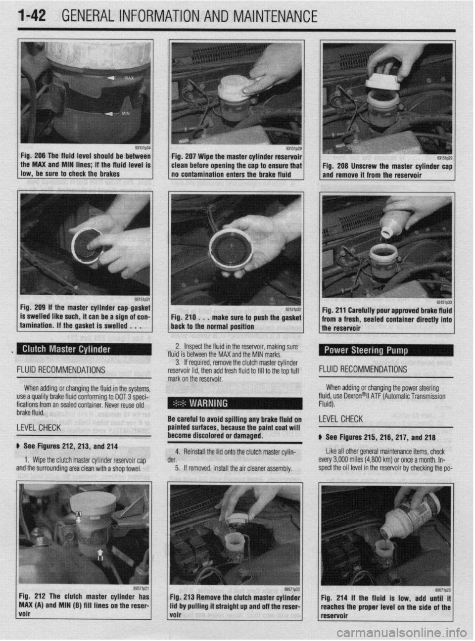
1-42 GENERAL~INFORMATION AND MAINTENANCE
Fig. 206 The fluid level should be between
llow,be*“retoch~ckiebrake~ . the MAX and MIN hnes if the fhud level IS
93151p31 Fig. 209 If the master cylinder capgasket
is swelled like such, it can be a sign of con-
tamination. If the gasket is swelled . . . Fig. 207 Wipe the master cylinder reservoir
clean before opening the cap to ensure that
no contamination enters the brake fluid
Fig. 210 . . .
make sure to push the gasket
back to the normal position
93151p29 I Fig. 208 Unscrew the master cylinder cap
and remove it from the reservoir
Fig. 211 Carefully pour approved brake fluid
from a fresh, sealed container directly into
the reservoir
2. Inspect the fluid in the reservoir, making sure
fluid is between the MAX and the MIN marks.
FLUID RECOMMENDATIONS
When adding or changing the fluid in the systems,
use a quality brake fluid conforming to DOT 3 speci-
fications from an sealed container. Never reuse old
brake fluid.
LEVEL CHECK
b See Figures 212, 213, and 214
1. Wipe the clutch master cylinder reservoir cap
and the surrounding area clean with a shop towel. 3. If required, remove the clut ch master cylinder
reservoir lid. then add fresh fluid I FLUID RECOMMENDATIONS
mark on the’reservoir. to fill to the top full
When adding or changing the power steering
fll$,“” Dexron@il ATF (Automatic Transmission
-
- .
Be careful to avoid sf Billing any brake fluid on LEVELCHECK
painted surfaces, bet
:ause the paint coat will
become discolored or damaged.
b See Figures 215, 216, 217, and 218
4. Reinstall the lid onto the clutch master cylin- Like all other general maintenance items, check
der. every 3,OOfl miles (4,800 km) or once a month. In-
5. If removed, install the air cleaner assembly. spect the oil level in the reservoir by checking the po-
Fig. 212 The clutch master cylinder has
MAX (A) and MIN (B) fill lines on the reser
volr
Page 42 of 408
GENERALINFORMATIONAND MAINTENANCE l-43
l Special car washing detergent is the best to
use. Liquid dishwashing detergent can remove wax
and leave the car’s paint unprotected and in addition
some liquid detergents contains abrasives which can
scratch the paint.
l Bird droppings should be removed from the
paintwork as soon as possible, otherwise the finish
may be permanently stained.
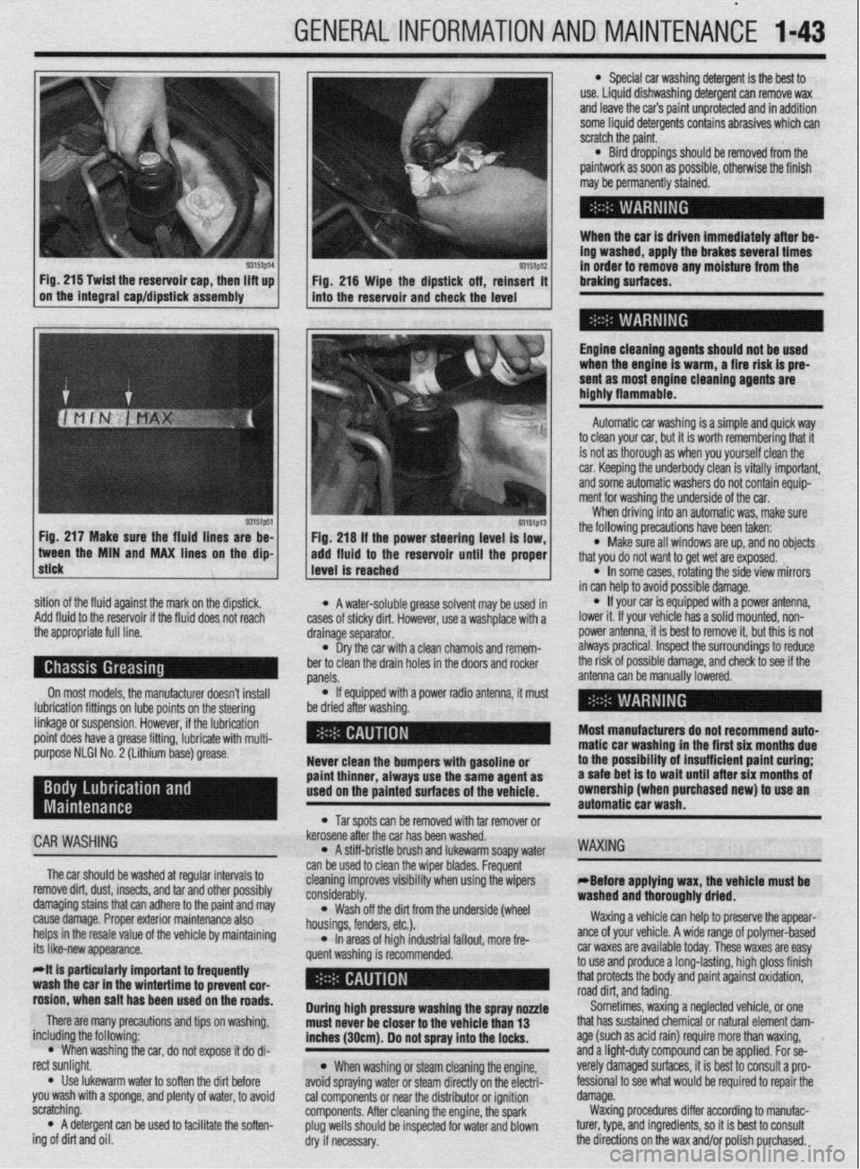
When the car is driven immediately after be-
ing washed, apply the brakes several times
93151p14 93151p12 Fig. 215 Twist the reservoir cap, then lift up
I I
in order to remove any moisture from the
Fig. 216 Wipe the dipstick off, reinsert it braking surfaces.
on the integral cap/dipstick assembly
into the reservoir and check the level
I
Engine cleaning agents should not be used
when the engine is warm, a fire risk is pre-
sent as most engine cleaning agents are
highly flammable.
sition of the fluid against the mark on the dipstick,
Add fluid to the reservoir if the fluid does not reach
the appropriate full line.
On most models, the manufacturer doesn’t install
lubrication fittings on lube points on the steering
linkage or suspension. However, if the lubrication
point does have a grease fitting, lubricate with multi-
purpose NLGI No. 2 (Lithium base) grease.
CAR WASHING
The car should be washed at regular intervals to
remove dirt, dust, insects, and tar and other possibly
damaging stains that can adhere to the paint and may
cause damage. Proper exterior maintenance also
helps in the resale value of the vehicle by maintaining
its like-new appearance.
Mt is particularly important ta frequentiy
wash the car in the wintertime to prevent cor-
rosion, when salt has been used on the roads.
There are many precautions and tips on washing,
including the following:
l When washing the car, do not expose it do di-
rect sunlight.
. Use lukewarm water to soften the dirt before
you wash with a sponge, and plenty of water, to avoid
scratching.
l A detergent can be used to facilitate the soften-
ing of dirt and oil. * A water-soluble grease solvent may be used in
cases of sticky dirt. However, use a washplace with a
drainage separator.
l Dry the car with a clean chamois and remem-
ber to clean the drain holes in the doors and rocker
panels.
l If equipped with a power radio antenna, it must
be dried after washing.
Never clean the bumpers with gasoline or
paint thinner, always use the same agent as
used on the painted surfaces of the vehicle.
l Tar spots can be removed with tar remover or
kerosene after the car has been washed.
l A stiff-bristle brush and lukewarm soapy water
can be used to clean the wiper blades. Frequent
cleaning improves visibility when using the wipers
considerably.
l Wash off the did from the underside (wheel
housings, fenders, etc.).
l In areas of high industrial fallout, more fre-
quent washing is recommended.
During high pressure washing the spray nonle
must never be closer to the vehicle than 13
inches (30cm). Do not spray into the locks.
l When washing or steam cleaning the engine,
avoid spraying water or steam directly on the electri-
cal components or near the distributor or ignition
components. After cleaning the engine, the spark
plug wells should be inspected for water and blown
dry if necessary. Automatic car washing is a simple and quick way
to clean your car, but it is worth remembering that it
is not as thorough as when you yourself clean the
car. Keeping the underbody clean is vitally important,
and some automatic washers do not contain equip-
ment for washing the underside of the car.
When driving into an automatic was, make sure
the following precautions have been taken:
l Make sure all windows are up, and no objects
that you do not want to get wet are exposed.
l In some cases, rotating the side view mirrors
in can help to avoid possible damage.
l If your car is equipped with a power antenna,
lower it. If your vehicle has a solid mounted, non-
power antenna, it is best to remove it, but this is not
always practical. Inspect the surroundings to reduce
the risk of possible damage, and check to see if the
antenna can be manually lowered.
Most manufacturers do not recommend auto-
matic car washing in the first six months due
to the possibility of insufficient paint curing;
a safe bet is to wait until after six months of
ownership (when purchased new) to use an
automatic car wash.
WAXING
eBefore applying wax, the vehicle must be
washed and thoroughly dried.
Waxing a vehicle can help to preserve the appear-
ante of your vehicle. A wide range of polymer-based
car waxes are available today. These waxes are easy
to use and produce a long-lasting, high gloss finish
that protects the body and paint against oxidation,
road dirt, and fading.
Sometimes, waxing a neglected vehicle, or one
that has sustained chemical or natural element dam-
age (such as acid rain) require more than waxing,
and a light-duty compound can be applied. For se-
verely damaged surfaces, it is best to consult a pro-
fessional to see what would be required to repair the
damage.
Waxing procedures differ according to manufac-
turer, type, and ingredients, so it is best to consult
the directions on the wax and/or polish purchased.
Page 63 of 408
3-2 ENGINEANDENGINEOVERHAUL
REMOVAL &INSTALLATION
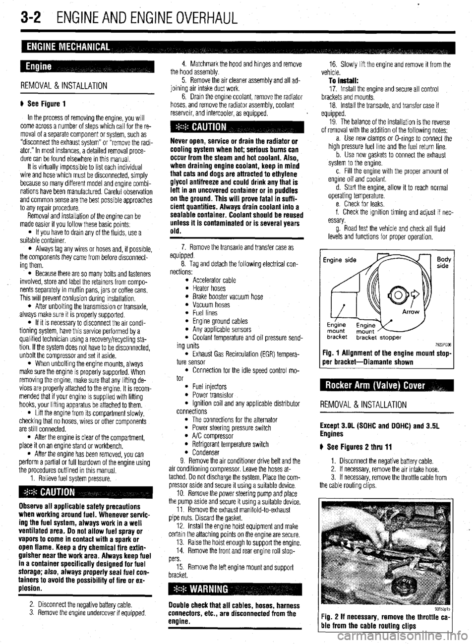
# See Figure 1
In the process of removing the engine, you will
come across a number of steps which call for the re-
moval of a separate component or system, such as
“disconnect the exhaust system” or “remove the radi-
ator.” In most instances, a detailed removal proce-
dure can be found elsewhere in this manual.
It is virtually impossible to list each individual
wire and hose which must be disconnected, simply
because so many different model and engrne combi-
nations have been manufactured Careful observation
and common sense are the best possible approaches
to any repair procedure.
Removal and installation of the engine can be
made easier if you follow these basic points:
l If you have to drain any of the fluids, use a
suitable container.
l Always tag any wires or hoses and, if possrble,
the components they came from before disconnect-
ing them.
l Because there are so many bolts and fasteners
involved, store and label the retainers from compo-
nents separately in muffin pans, jars or coffee cans.
This will prevent confusion during installatron.
l After unbolting the transmisston or transaxle,
always make sure it is properly supported.
l If it is necessary to disconnect the air condi-
tioning system, have this service performed by a
qualified technician using a recovery/recycling sta-
tion If the system does not have to be disconnected,
unbolt the compressor and set it aside.
l When unbolting the engine mounts, always
make sure the engine is properly supported. When
removing the engine, make sure that any lifting de-
vices are properly attached to the engine. It is recom-
mended that if your engine IS supplied with lifting
hooks, your lifting apparatus be attached to them.
l Lift the engine from its compartment slowly,
checking that no hoses, wires or other components
are still connected.
l After the engine is clear of the compartment,
place it on an engine stand or workbench.
l After the engine has been removed, you can
perform a partial or full teardown of the engine using
the procedures outlined in this manual.
1. Relieve fuel system pressure.
Observe all applicable safety precautions
when working around fuel. Whenever servic-
ing the fuel system, always work in a well
ventilated area. Do not allow fuel spray or
vapors to come in contact with a spark or
open flame. Keep a dry chemical fire extin-
guisher near the work area. Always keep fuel
in a container specifically designed for fuel
storage; also, always properly seal fuel con-
tainers to avoid the possibility of fire or ex-
plosion.
2. Disconnect the negative battery cable.
3. Remove the engine undercover if equipped. 4. Matchmark the hood and hinges and remove
the hood assembly.
5. Remove the air cleaner assembly and all ad-
joining air intake duct work.
6. Drain the engine coolant, remove the radiator
hoses, and remove the radiator assembly, coolant
reservoir, and intercooler, as equipped.
cooling system when hot; serious burns can
occur from the steam and hot coolant. Also,
when draining engine coolant, keep in mind
that cats and dogs are attracted to ethylene
glycol antifreeze and could drink any that is
left in an uncovered container or in puddles
on the ground. This will prove fatal in suffi-
cient quantities. Always drain coolant into a
sealable container. Coolant should be reused
unless it is contaminated or is several years
old.
7. Remove the transaxle and transfer case as
equipped.
8. Tag and detach the following electrical con-
nections:
l Accelerator cable l Heater hoses l Brake booster vacuum hose l Vacuum hoses l Fuel lines l Engine ground cables l Any applicable sensors l Coolant temperature and oil pressure send-
ing units
l Exhaust Gas Recirculation (EGR) tempera-
ture sensor
l Connection for the idle speed control mo-
tor
l Fuel injectors l Power transistor l Ignition coil and any applicable distributor
connections
l The connections for the alternator l Power steering pressure switch l A/C compressor l Refrigerant temperature switch l Condenser
9. Remove the air conditioner drive belt and the
air conditioning compressor. Leave the hoses at-
tached. Do not discharge the system. Place the com-
pressor aside and secure it using a suitable device.
10. Remove the power steering pump and place
the pump asrde and secure it using a surtable device.
11. Remove the exhaust manifold-to-exhaust
pipe nuts. Discard the gasket.
12. Install the engine hoist equipment and make
certain the attaching points on the engine are secure.
13. Raise the hoist enough to support the engine.
14. Remove the front and rear engine roll stop-
pers
15. Remove the left engine mount and support
Double check that all cables, hoses, harness
connectors, etc., are disconnected from the
engine.
16. Slowly lift the engine and remove it from the
vehicle.
To install:
17. Install the engine and secure all control
brackets and mounts.
18. Install the transaxle, and transfer case if
equipped.
19. The balance of the installation is the reverse
of removal with the addition of the following notes:
a. Use new clamps or O-rings to connect the
high pressure fuel lme and the fuel return line.
b. Use new gaskets to connect the exhaust
system to the engine.
c. Fill the engine with the proper amount of
engine oil and coolant.
d. Start the engine, allow it to reach normal
operating temperature.
e. Check for leaks.
f. Check the ignition timing and adjust if nec-
essary.
g. Road test the vehicle and check all fluid
levels and functions for proper operation.
Fig. 1 Alignment of the engine mount stop-
oer bracket-Diamante shown
REMOVAL &INSTALLATION
Except 3.OL (SOHC and DOHC) and 3.5L
Engines
# See Figures 2 thru 11
1. Disconnect the negative battery cable.
2. If necessary, remove the air intake hose.
3. If necessary, remove the throttle cable from
the cable routing clips.
Fig. 2 If necessary, remove the throttle ca-
ble from the cable routing clips
Page 78 of 408
ENGlNEANDENGlNEOVERHAiJL 3-17
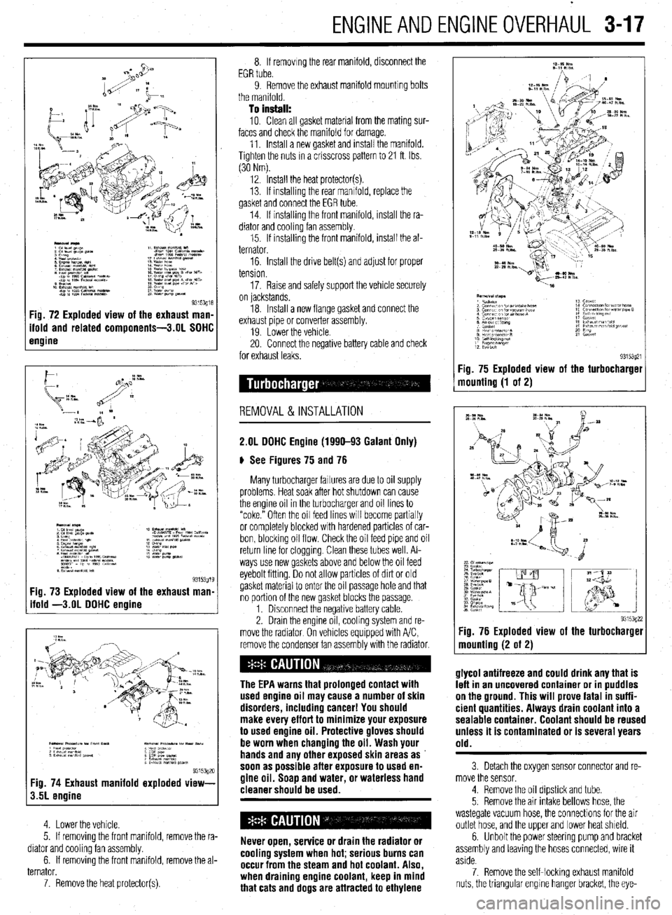
Fig. 73 Exploded view of the exhaust man
ifold -3.OL DOHC engine
9315392c Fig. 74 Exhaust manifold exploded view-
3.5L engine
4. Lower the vehicle.
5. If removing the front manifold, remove the ra-
diator and cooling fan assembly.
6. If removing the front manifold, remove the al-
ternator.
7. Remove the heat protector(s). 8. If removing the rear manifold, disconnect the
EGR tube.
9. Remove the exhaust manifold mounting bolts
the manifold.
To install:
10. Clean all gasket material from the mating sur-
faces and check the manifold for damage.
11. Install a new gasket and install the manifold.
Tighten the nuts in a crisscross pattern to 21 ft. Ibs.
(30 Nm).
12. Install the heat protector(s).
13. If installrng the rear manifold, replace the
gasket and connect the EGR tube.
14. If installing the front manifold, install the ra-
diator and cooling fan assembly.
15. If installing the front manifold, install the al-
ternator.
16. Install the drive belt(s) and adjust for proper
tension.
17. Raise and safely support the vehicle securely
on lackstands.
18. Install a new flange gasket and connect the
exhaust pipe or converter assembly.
19 Lower the vehicle
20. Connect the negative battery cable and check
for exhaust leaks.
REMOVAL&INSTALLATION
2.OL DOHC Engine (1990-93 Galant Only)
# See Figures 75 and 76
Many turbocharger failures are due to oil supply
problems. Heat soak after hot shutdown can cause
the engine oil in the turbocharger and oil lines to
“coke.” Often the oil feed lines will become partially
or completely blocked with hardened particles of car-
bon, blocking oil flow. Check the oil feed pipe and oil
return line for cloggrng. Clean these tubes well. Al-
ways use new gaskets above and below the oil feed
eyebolt fitting. Do not allow particles of dirt or old
gasket material to enter the oil passage hole and that
no portion of the new gasket blocks the passage.
1. Disconnect the negative battery cable.
2. Drain the engine oil, cooling system and re-
move the radiator On vehicles equipped with A/C,
remove the condenser fan assembly with the radiator.
The EPA warns that prolonged contact with
used engine oil may cause a number of skin
disorders, including cancer! You should
make every effort to minimize your exposure
to used engine oil. Protective gloves should
be worn when changing the oil. Wash your
hands and any other exposed skin areas as
soon as possible after exposure to used en-
gine oil. Soap and water, or waterless hand
cleaner should be used.
Never open, service or drain the radiator or
cooling system when hot; serious burns can
occur from the steam and hot coolant. Also,
when draining engine coolant, keep in mind
that cats and dogs are attracted to ethylene Fig. 75 Exploded view
mounting (1 of 2)
93153q21 the turbocharget
9315392: :ig. 76 Exploded view of the turbocharger
nounting (2 of 2)
glycol antifreeze and could drink any that is
left in an uncovered container or in puddles
on the ground. This will prove fatal in suffi-
cient quantities. Always drain coolant into a
sealable container. Coolant should be reused
unless it is contaminated or is several years
old.
3 Detach the oxygen sensor connector and re-
move the sensor.
4. Remove the oil dipstick and tube.
5. Remove the air intake bellows hose, the
wastegate vacuum hose, the connections for the air
outlet hose, and the upper and lower heat shield.
6. Unbolt the power steering pump and bracket
assembly and leaving the hoses connected, wire it
aside.
7. Remove the self-locking exhaust manifold
nuts, the triangular engrne hanger bracket, the eye-
Page 79 of 408
l
3-18 ENGINEANDENGINEOVERHAUL
bolt and gaskets that connect the oil feed line to the
turbo center section and the water cooling lines. The
water line under the turbo has a threaded connection.
8. Remove the exhaust pipe nuts and gasket and
lift off the exhaust manifold. Discard the gasket,
9. Remove the 2 through bolts and 2 nuts that 16. If removed, install the power steering pump
and bracket.
17. Install the heat shields, air outlet hose, waste-
gate hose and air intake bellows.
18. Install the oil dipstick tube and dipstick. In-
stall the oxyqen sensor. cient quantities. Always drain coolant into a
sealable container. Coolant should be reused
unless it is contaminated or is several years
old.
3. Disconnect the overflow tube. Some vehicles
hold the exhaust manifold to the turbocharger,
10. Remove the 2 capscrews from the oil return
line (under the turbo). Discard the gasket. Separate
the turbo from the exhaust manifold. The 2 water
pipes and oil feed line can still be attached. 19. In&h the radiator assembly.
20. Fill the engine with oil, fill the cooling system
and reconnect the negative battery cable.
11. Visually check the turbine wheel (hot side)
and compressor wheel (cold side) for cracking or
other damage. Check whether the turbine wheel and
the compressor wheel can be easily turned by hand.
Check for oil leakaae. Check whether or not the Operating the engine without the proper
amount and type of engine oil will result in
severe engine damage.
wastegate valve remains open. If any problem is .
found, replace the part. Inspect oil passages for re- #I , I
striction or deposits and clean as required,
12. The wasteaate can be checked with a ores-
REMOVAL & INSTALLATION sure tester. Apply approximately 9 psi to the&h&or
and make sure the rod moves. Do not apply more
than 10.3 psi or the diaphragm in the wastegate may
be damaged. Vacuum applied to the wastegate actua-
tor should be maintained, replace if leaks vacuum,
Do not attempt to adjust the wastegate valve. $ See Figures 77 thru 91
I. Disconnect the negative battery cable.
2. Drain the cooling system when safe.
To
install: 13. Prime the oil return line with clean engine oil.
Replace all locking nuts. Before installing the
threaded connection for the water inlet pipe, apply
light oil to the inner surface of the pipe flange. As-
semble the turbocharger and exhaust manifold.
14. Install the exhaust manifold using a new gas-
ket.
15. Connect the water cooling lines, oil feed line
and engine hanger. Never open, service or drain the radiator or
cooling system when hot: serious burns can
occur from the steam and hot coolant. Also,
when draining engine coolant, keep in mind
that cats and dogs are attracted to ethylene
glyeol antifreeze and could drink any that is
left in an uncovered container or in puddles
on the ground. This will prove fatal in suffi-
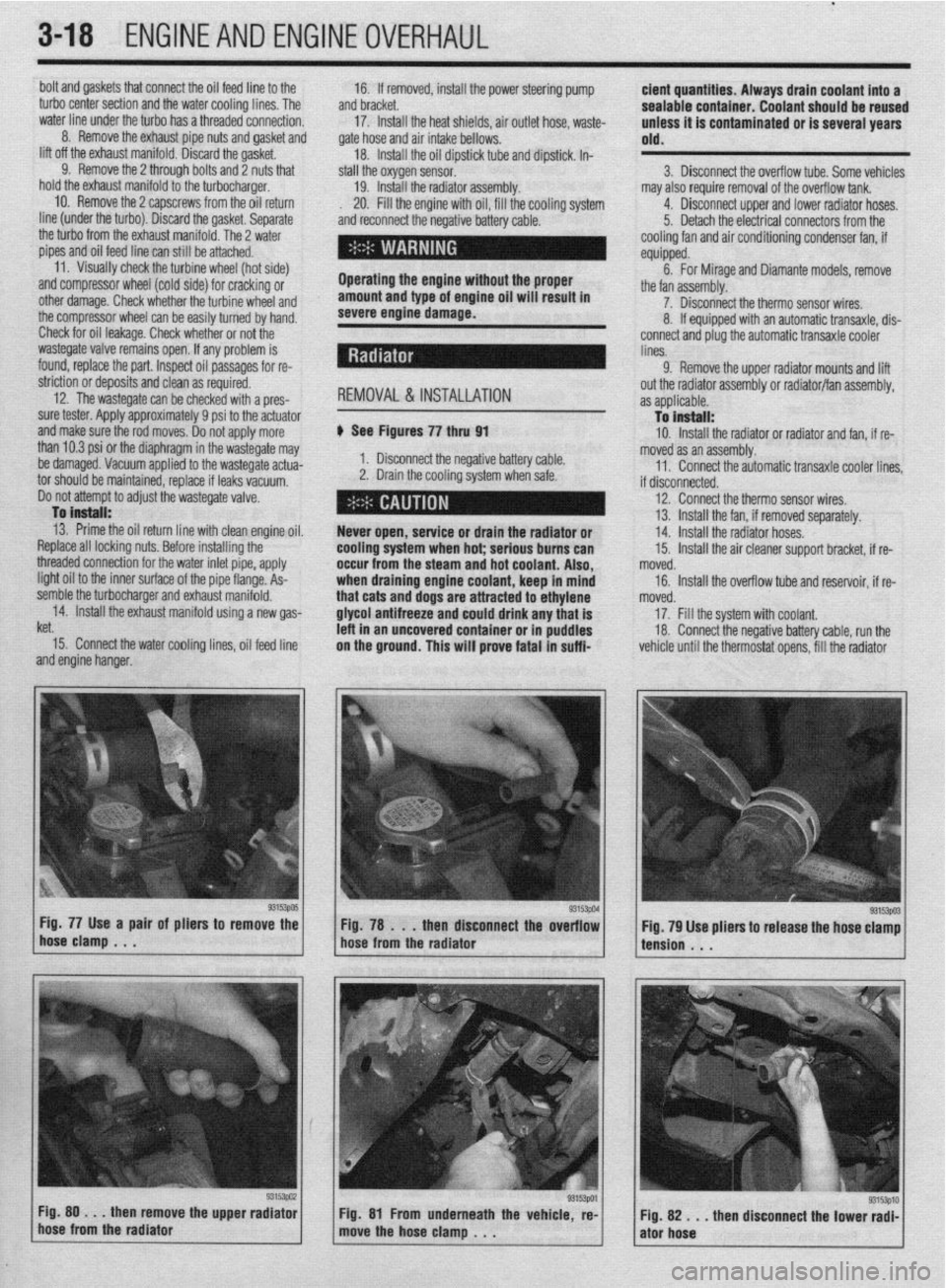
Fig. 77 Use a pair of pliers to remove the
Fig. 78 . . .
then disconnect the overflow
hose clamp . . .
hose from the radiator may also require removal of the overflow tank.
4. Disconnect upper and lower radiator hoses.
5. Detach the electrical connectors from the
cooling fan and air conditioning condenser fan, if
equipped.
6. For Mirage and Diamante models, remove
the fan assembly.
7. Disconnect the therm0 sensor wires,
8. If equipped with an automatic transaxle, dis-
connect and plug the automatic transaxle cooler
lines.
9. Remove the upper radiator mounts and lift
out the radiator assembly or radiator/fan assembly,
as applicable.
To install:
10. Install the radiator or radiator and fan, if re-
moved as an assembly.
11. Connect the automatic transaxle cooler lines
if disconnected.
12. Connect the therm0 sensor wires,
13. Install the fan, if removed separately.
14. Install the radiator hoses.
15. Install the air cleaner support bracket, if re-
noved.
16. Install the overflow tube and reservoir, if re-
noved.
17. Fill the system with coolant.
18. Connect the negative battery cable, run the
vehicle until the thermostat opens, fill the radiator
93153003 Fig. 79 Use pliers to release the hose clamp
tension . . .
Fig. 80 . . .
then remove the upper radiator
hose from the radiator Fig. 81 From underneath the vehicle, re-
move the hose clamp , . . ”
then disconnect the lower radi- Fig. 82 . . .
ator hose
Page 81 of 408
.
3-20 ENGINEANDENGINEOVERHAUL
Never open, service or drain the radiator or
cooling system when hot; serious burns can
occur from the steam and hot coolant. Also,
when draining engine coolant, keep in mind
that cats and dogs are attracted to ethylene
glycol antifreeze and could drink any that is
left in an uncovered container or in puddles
on the ground. This will prove fatal in suffi-
cient quantities. Always drain coolant into a
sealable container. Coolant should be reused
unless it is contaminated or is several years
old.
3. Remove the overflow hose and disconnect
the upper radiator hose.
*It is recommended that each clamp be
matchmarked to the hose. Observe the marks
and reinstall the clamps exactly when rein-
stalling the radiator.
4. If equipped with an automatic transaxle, re-
move and plug the fluid cooler hoses.
5. Unplug the electrical connector(s) from the
coolant fan motor.
6. Remove the mounting bolts, then remove the
fan and shroud assembly from the vehicle.
7. Remove the fan blade retainer nut from the
shaft on the fan motor and separate the fan from the
motor.
8. Remove the motor to shroud attaching
screws and the motor from the shroud.
To tnstall: 9. Install the motor to the shroud and secure
with the mounting bolts.
10. Install the remaining components in the re-
verse order of removal.
11. Fill the coohng system. Connect the negative
battery cable and check the cooling fan for proper op-
eration.
Diamante
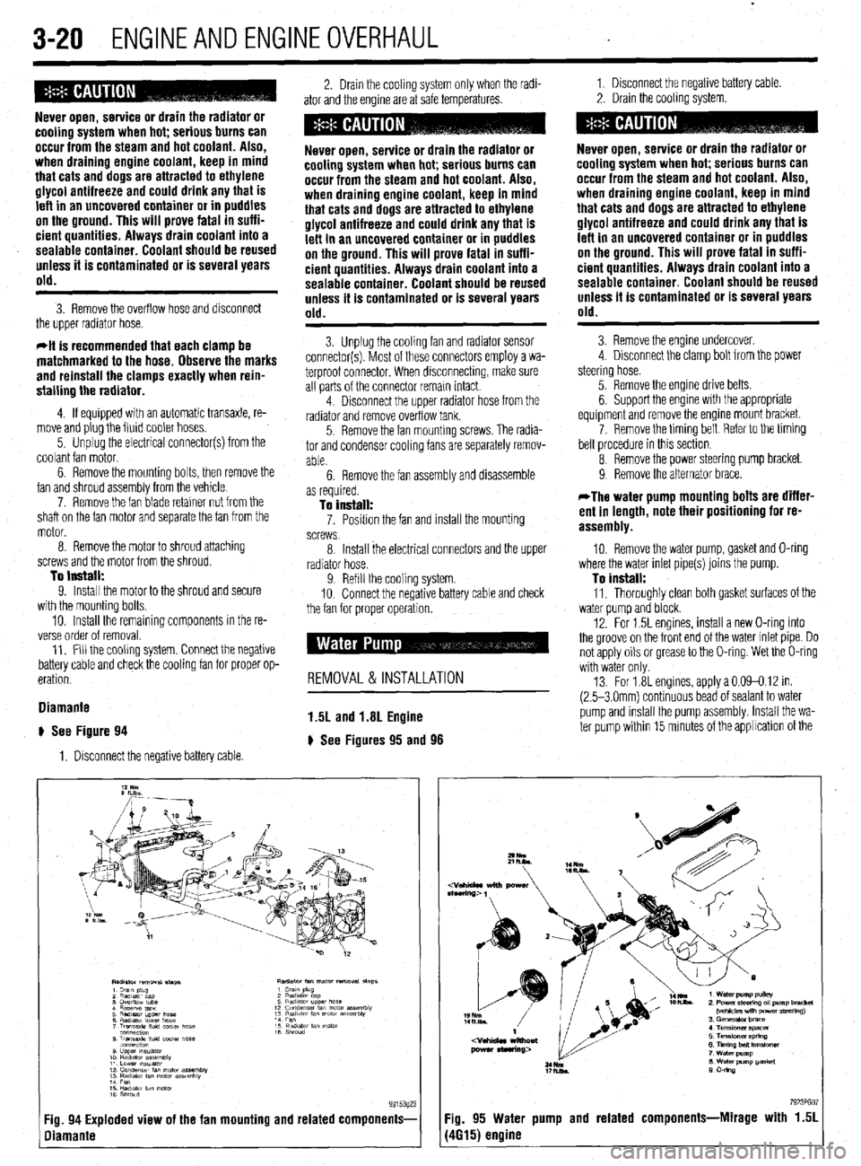
# See Figure 94
1. Disconnect the negative battery cable 2. Drain the cooling system only when the radi-
ator and the engine are at safe temperatures. 1. Disconnect the negative battery cable
2. Drain the cooling system.
Never open, service or drain the radiator or
cooling system when hot; serious burns can
occur from the steam and hot coolant. Also,
when draining engine coolant, keep in mind
that cats and dogs are attracted to ethylene
glycol antifreeze and could drink any that is
left in an uncovered container or in puddles
on the ground. This will prove fatal in suffi-
cient quantities. Always drain coolant into a
sealable container. Coolant should be reused
unless it is contaminated or is several years
old.
3. Unplug the cooling fan and radiator sensor
connector(s). Most of these connectors employ a wa-
terproof connector. When disconnecting, make sure
all parts of the connector remain intact.
4. Disconnect the upper radiator hose from the
radiator and remove overflow tank.
5. Remove the fan mounting screws. The radia-
tor and condenser cooling fans are separately remov-
able.
6. Remove the fan assembly and disassemble
Never open, service or drain the radiator or
cooling system when hot; serious burns can
occur from the steam and hot coolant. Also,
when draining engine coolant, keep in mind
that cats and dogs are attracted to ethylene
glycol antifreeze and could drink any that is
left in an uncovered container or in puddles
on the ground. This will prove fatal in suffi-
cient quantities. Always drain coolant into a
sealable container. Coolant should be reused
unless it is contaminated or is several years
old.
3. Remove the engine undercover.
4 Disconnect the clamp bolt from the power
steering hose.
5. Remove the engine drive belts.
6. Support the engine with the appropriate
equipment and remove the engine mount bracket.
7. Remove the timing belt Reier to the timing
belt procedure in this section
8 Remove the power steering pump bracket.
9. Remove the alternator brace.
as required.
To install: 7. Posrtion the fan and install the mounting
screws
*The water pump mounting bolts are differ-
ent in length, note their positioning for re-
assembly.
8 Install the electrical connectors and the upper
radiator hose.
9. Refill the cooling system.
IO. Connect the negative battery cable and check
the fan for orooer ooeration. 10. Remove the water pump, gasket and O-ring
where the water inlet pipe(s) joins the pump.
To install: 11, Thoroughly clean both gasket surfaces of the
water oumo and block.
12. For 1.5L engines, install a new O-ring into
the groove on the front end of the water inlet pipe. Do
not apply oils or grease to the O-ring. Wet the O-ring
with water only
13. For 1.8L engines, apply a 0.09-0.12 in.
(2.5-3 Omm) continuous bead of sealant to water
pump and rnstall the pump assembly. Install the wa-
ter pump within 15 minutes of the applrcation of the
REMOVAL & INSTALLATION
1.5L and 1.8L Engine
) See Figures 95 and 98
7923PGO :ig. 94 Exploded view of the fan mounting and related components- Fig. 95 Water pump and related components-Mirage with 1.51
liamante (4615) engine