clock MITSUBISHI ECLIPSE 1991 Owner's Manual
[x] Cancel search | Manufacturer: MITSUBISHI, Model Year: 1991, Model line: ECLIPSE, Model: MITSUBISHI ECLIPSE 1991Pages: 1216, PDF Size: 67.42 MB
Page 906 of 1216
21-212AUTOMATIC TRANSAXLE -Service Adiustment Procedures
1750464
KICKOOWN SERVO ADJUSTMENTNZlFRAB1. Completely remove all dirt and other materials adhered
G+around the kickdown servo switch.
-i-s-2. Remove the snap ring.
3. Remove the kickdown servo switch.
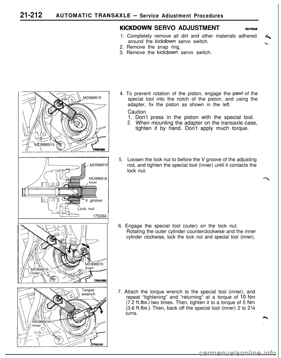
4. To prevent rotation of the piston, engage the
pawl of the
special tool into the notch of the piston, and using the
adapter, fix the piston as shown in the left.
Caution1. Don’t press in the piston with the special tool.
2.When mounting the adapter on the transaxle case,
tighten it by hand. Don’t apply much torque.
5.Loosen the lock nut to before the V groove of the adjusting
rod, and tighten the special tool (inner) until it contacts the
lock nut.
6. Engage the special tool (outer) on the lock nut.
Rotating the outer cylinder counterclockwise and the inner
cylinder clockwise, lock the lock nut and special tool (inner).7. Attach the torque wrench to the special tool (inner), and
repeat “tightening” and “returning” at a torque of
IO Nm
(7.2
ft.lbs.) two times. Then, tighten it to a torque of 5 Nm
(3.6
ftlbs.). Then, back off the special tool (inner) 2 to 2%
turns.*
. .
Page 907 of 1216
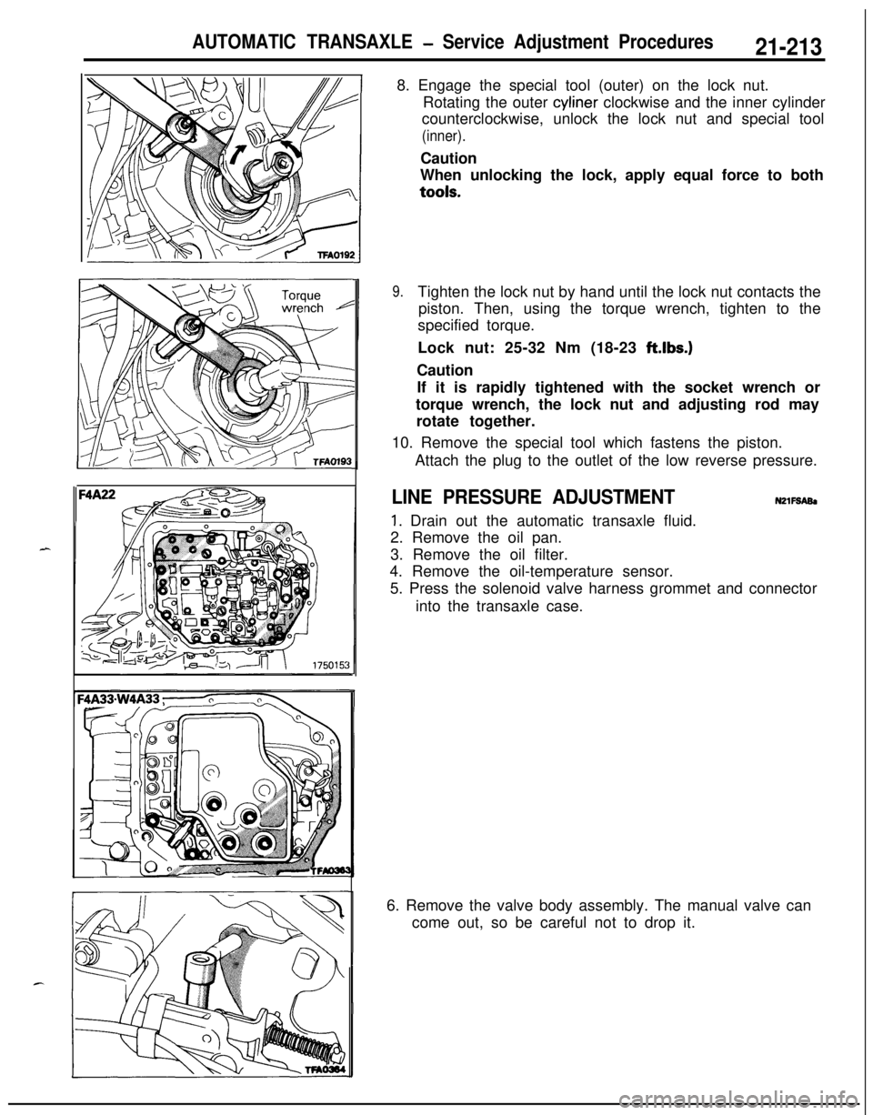
AUTOMATIC TRANSAXLE - Service Adjustment Procedures21-2138. Engage the special tool (outer) on the lock nut.
Rotating the outer cyliner clockwise and the inner cylinder
counterclockwise, unlock the lock nut and special tool
(inner).Caution
When unlocking the lock, apply equal force to bothtools.
9.Tighten the lock nut by hand until the lock nut contacts the
piston. Then, using the torque wrench, tighten to the
specified torque.
Lock nut: 25-32 Nm (18-23 ft.lbs.)
Caution
If it is rapidly tightened with the socket wrench or
torque wrench, the lock nut and adjusting rod may
rotate together.
10. Remove the special tool which fastens the piston.
Attach the plug to the outlet of the low reverse pressure.
LINE PRESSURE ADJUSTMENTN2lFSABl
1. Drain out the automatic transaxle fluid.
2. Remove the oil pan.
3. Remove the oil filter.
4. Remove the oil-temperature sensor.
5. Press the solenoid valve harness grommet and connector
into the transaxle case.
6. Remove the valve body assembly. The manual valve can
come out, so be careful not to drop it.
Page 908 of 1216
21-214AUTOMATIC TRANSAXLE - Service Adjustment Procedures
'50157
F4
1
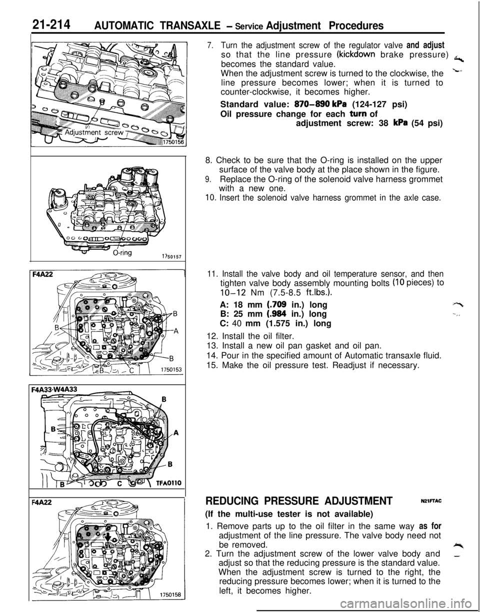
7.Turn the adjustment screw of the regulator valve and adjustso that the line pressure
(kickdown brake pressure) a,becomes the standard value.
When the adjustment screw is turned to the clockwise, the
Lline pressure becomes lower; when it is turned to
counter-clockwise, it becomes higher.
Standard value:
870-890 kPa (124-127 psi)
Oil pressure change for each turq of
adjustment screw: 38
kPa (54 psi)
8. Check to be sure that the O-ring is installed on the upper
surface of the valve body at the place shown in the figure.
9.Replace the O-ring of the solenoid valve harness grommet
with a new one.
10. Insert the solenoid valve harness grommet in the axle case.
11. Install the valve body and oil temperature sensor, and then
(IO pieces) to
tighten valve body assembly mounting bolts
IO-12 Nm (7.5-8.5 ft.lbs.).A: 18 mm
(.709 in.) long
B: 25 mm
(.984 in.) long
C: 40 mm (1.575 in.) long
12. Install the oil filter.
13. Install a new oil pan gasket and oil pan.
14. Pour in the specified amount of Automatic transaxle fluid.
15. Make the oil pressure test. Readjust if necessary.
+-t
--,,
REDUCING PRESSURE ADJUSTMENTNZlFTAC(If the multi-use tester is not available)
1. Remove parts up to the oil filter in the same way as for
adjustment of the line pressure. The valve body need not
be removed.
+%2. Turn the adjustment screw of the lower valve body and_adjust so that the reducing pressure is the standard value.
When the adjustment screw is turned to the right, the
reducing pressure becomes lower; when it is turned to the
left, it becomes higher.
Page 1046 of 1216
23-2
SPECIFICATIONS
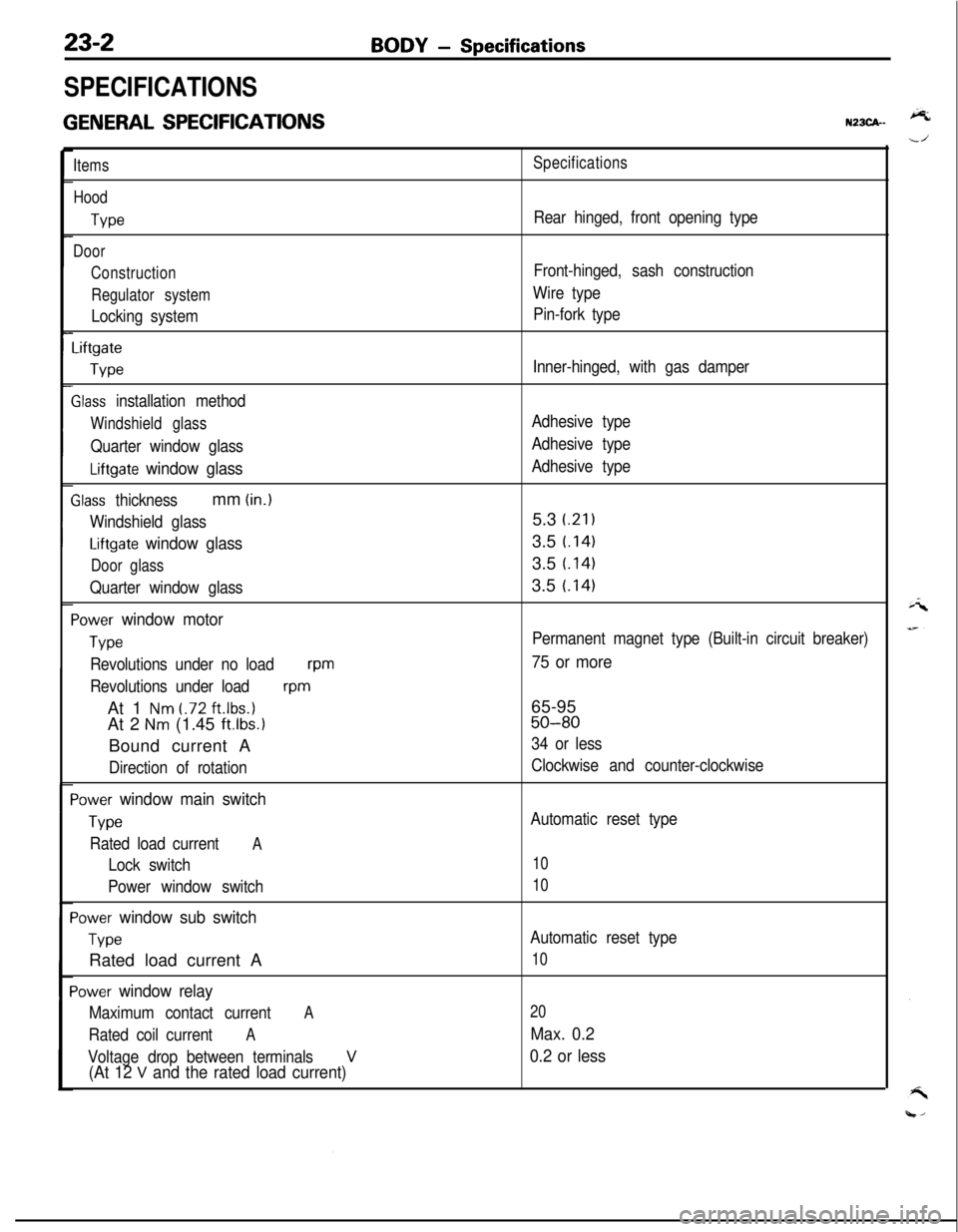
GENERAL SPECIFICATIONS
BODY - Specifications
N23CA--
Items
Hood
We
Door
Construction
Regulator system
Locking system
Liftgate
We
Slass installation method
Windshield glass
Quarter window glass
Liftgate window glass
Zlass thicknessmm (in.)
Windshield glass
Liftgate window glass
Door glass
Quarter window glass
‘ower window motor
Type
Revolutions under no loadwm
Revolutions under load
wmAt 1
Nm t.72 ft.lbs.1At 2
Nm (1.45 ft.lbs.1Bound current A
Direction of rotation
‘ower window main switch
Type
Rated load currentA
Lock switch
Power window switch
‘ower window sub switch
TvwRated load current A
‘ower window relay
Maximum contact currentA
Rated coil currentA
Voltage drop between terminalsV(At 12 V and the rated load current)
Specifications
Rear hinged, front opening type
Front-hinged, sash construction
Wire type
Pin-fork type
Inner-hinged, with gas damper
Adhesive type
Adhesive type
Adhesive type5.3
i.21)3.5
t.1413.5
t.1413.5
t.141
Permanent magnet type (Built-in circuit breaker)
75 or more65-95
50-80
34 or less
Clockwise and counter-clockwise
Automatic reset type
10
10
Automatic reset type
10
20
Max. 0.2
0.2 or less
Page 1114 of 1216
23-70BODY- Door Handle and Latch/Central Door Lockina Svstem
I18AO750 1lBY3611 I.- .--,
!-
II
T!3123
18PO39i
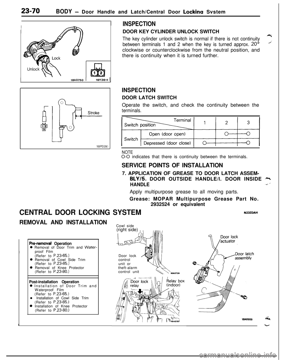
INSPECTIONDOOR KEY CYLINDER UNLOCK SWITCH
The key cylinder unlock switch is normal if there is not continuity7
between terminals 1 and 2 when the key is turned approx. 20”’clockwise or counterclockwise from the neutral position, and
there is continuity when it is turned further.
INSPECTIONDOOR LATCH SWITCH
Operate the switch, and check the continuity between the
terminals.
NOTEO-O indicates that there is continuity between the terminals.
SERVICE POINTS OF INSTALLATION7. APPLICATION OF GREASE TO DOOR LATCH ASSEM-
BLY/5. DOOR OUTSIDE HANDLE/l. DOOR INSIDE rr,
HANDLE.< ‘Apply multipurpose grease to all moving parts.
Grease: MOPAR Multipurpose Grease Part No.
2932524 or equivalent
CENTRAL DOOR LOCKING SYSTEMN23ZDAI-I
REMOVAL AND INSTALLATION
Pre-removal Operation0 Removal of Door Trim and Water-
Iproof Film
(Refer to P.23-65.)
0 Removal of Cowl Side Trim
(Refer to P.23-85.)
0 Removal of Knee Protector
(Refer to P.23-80.)
Post-installation Operation0 Installation of Door Trim and
Waterproof Film
(Refer to P.23-65.)
l Installation of Cowl Side Trim
(Refer to P.23-85.)
0 Installation of Knee Protector
(Refer to P.23-80.)
ICowl side
(right side) , ,
Door lock
control
unit or
theft-alarm
control unit
Page 1159 of 1216
HEATERS AND AIR CONDITIONING - Service Adjustment Procedures 24-15
Liquid
line
\Liquid lineI
ILiquid lineHigh pressure
hose2010439
detector torch
Electric leakAdetector tester
2OUO338
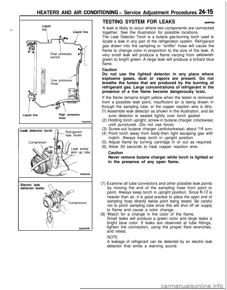
TESTING SYSTEM FOR LEAKSNUFFADA leak is likely to occur where two components are connected
together. See the illustration for possible locations.
The Leak Detector Torch is a butane gas-burning torch used to
locate a leak in any part of the refrigeration system.Refrigerantgas drawn into the sampling or “sniffer” hose will cause the
flame to change color in proportion to the size of the leak. A
very small leak will produce a flame varying from yellowish-
green to bright green. A large leak will produce a briliant blue
flame.Caution
Do not use the lighted detector in any place where
explosive gases, dust or vapors are present. Do not
breathe the fumes that are produced by the burning of
refrigerant gas. Large concentrations of refrigerant in the
presence of a live flame become dangerously toxic.
If the flame remains bright yellow when the tester is removed
from a possible leak point, insufficient air is being drawn in
through the sampling tube, or the copper reaction wire is dirty.
(1) Assemble leak detector as shown in the illustration, and be
sure detector is seated tightly over torch gasket.
(2) Holding torch upright, screw-in butane charger (clockwise)
until punctured. (Do not use force).
(3) Screw-out butane charger (anticlockwise) about
l/4 turn.
(4) Point torch away from body-then light escaping gas with
match. Always keep torch in upright position.
(5) Adjust flame by turning cartridge in or out as required.
(6) Allow 30 seconds to heat copper reaction wire.
Caution
Never remove butane charger while torch is lighted or
in the presence of any open flame.
(7) Examine all tube connectors and other possible leak points
by moving the end of the sampling hose from point to
point. Always keep torch in upright position. Since
R-12 is
heavier than air, it is good practice to place the open end of
sampling hose directly below point being tested. Be careful
not to pinch sampling tube since this will shut off air supplyto flame and cause a color change.
(8) Watch for a change in the color of the flame.
Small leaks will produce a green color and large leaks a
bright blue color. If leaks are observed at tube fittings,
tighten the connection, using the proper flare wrenches,
and retest.
NOTE
A leakage of refrigerant can be detected by an electric leakdetector that emits a warning sound.
Page 1162 of 1216
24-18 HEATERS AND AIR CONDITIONING - Service Adjustment Procedures
(5) Screw a can of R-12 to the opened manifold valve. Be sure
gasket is in place and in good condition. Tighten refrigerantcan and manifold locking nut to insure a good seal. Do not
overtighten 8 to
11 Nm (6 to 8 ft.lbs.) is sufficient if gasket
is in good condition.
(6) Turn manifold valve (above the refrigerant can) completely
clockwise to puncture the can. This closes the valve and
seals the refrigerant in the can.
Caution
Never heat small cans of refrigerant over
40°C (104°F)as they may explode.
(7) Place the refrigerant in a large pan of water heated to 52°C
(104°F). Place pan of water containing the refrigerant can
on an accurate scale so the amount of refrigerant added
can be weighed. Open the refrigerant manifold valve.
(8) Purge all air from test hoses. Air in the system will be
trapped in the condenser causing abnormally high dis-
charge pressures and interfering with condensing of the
refrigerant.(9) Slightly loosen both test hoses at the gauge set manifold.
Tighten the hoses as soon as the air is purged.
(10)Slightly loosen charging hose connection at gauge set
manifold. This will purge air from the charging hose.
Tighten connection as soon as air is purged.
(I l)With vehicle windows open and hood up, operate engine at1,500 rpm and jump the low pressure switch terminals
located on the receiver drier so the clutch will remain
engaged.
(12)Place air conditioner control on air conditioner and place theblower switch on high.
(13)lf necessary, block the condenser to maintain a discharge
pressure of 1,422 to 1,520
kPa (206 to 220 psi). System
must be charged through the evaporator suction service
ports as follows:
(a) Slowly open the suction service gauge valve.
Meter flow of refrigerant by adjusting, the suciton
service gauge valve so that pressure registered at the
suction service gauge does not exceed 345 kPa (50 psi).Keep refrigerant container upright.
(b) Add refrigerant gas until there is no foam visible at the
sight glass.
Add an additional
170 g (6 oz.)
(c) Close the suction gauge valve.
CautionToo much refrigerant in the system can cause
abnormally high discharge pressures. Care must beused so that the exact recommended amount or
refrigerant is added after foam clears in the sight
glass.(d) Close dispensing manifold valve. Remove test hoses
and adapters from the service ports of compressor,
install protective caps at service ports and reconnect
wiring.(e) Check system performance.
(P.24- 16.)
e
. i”
A
i-4
Page 1165 of 1216
i
HEATERS AND AIR CONDITIONING - Service Adjustment Procedures 24-21Hot water40°C (104°F)
1467CHARGING SYSTEM
The refrigerant system must have been evacuated using the
previous procedure before charging.
Charge using only R-l 2 refrigerant.
R-12 is available in bulk
tanks or small cans. Follow the safety precautions for handling
R-12 as listed in this group.
Charging with Small Cans
When using disposable cans of this type, follow carefully the
can manufacturers instructions.
Caution
Never use these cans to charge into the high pressure side
of the system (compressor discharge port) or into a systemthat is at high temperature, because the high system
pressures could be transferred into the charging can
causing it to explode.
Keep the refrigerant manifold valves capped when not in use.
Keep a supply of extra refrigerant-can-to-refrigerant-manifold
gaskets on hand so that gaskets can be replaced periodically.
This will insure a good seal without excessive tightening of thecan or the manifold nuts.
(1) Attach center hose from manifold gauge set to refrigerant
dispensing manifold. Turn refrigerant manifold valves com-pletely anticlockwise so they are fully open.
Remove protective caps from refrigerant manifold.
(2) Screw refrigerant cans into manifold. Be sure
manifold-to-can gasket is in place and in good condition. Tighten can
and manifold nuts to 8 to 11 Nm (6 to 8
ft.lbs.).(3) Turn refrigerant manifold valves completely clockwise to
puncture the cans and close the manifold valves.
(4) Purge the air from the charging line by loosening the
charging hose at the gauge set manifold and turning one ofthe refrigerant valves anticlockwise to release refrigerant.
When the refrigerant gas starts escaping from the loose
connection, re-tighten the hose.
Caution
Never heat small refrigerant cans over
40°C (104°F) as
they may explode.
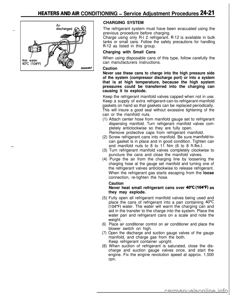
(5) Fully open all refrigerant manifold valves being used and
place the cans of refrigerant into a pan containing
40°C
(104°F) water. The water will warm the charging can and
aid in the transfer to the charge into the system. Place the
water pan and refrigerant cans on a scale and note the
weight.
(6)Place air conditioner control on air conditioner and place theblower switch on high.
(7) Open the discharge and suction gauge valves of the gaugemanifold, and charge gas from the both.
Keep refrigerant container upright.
(8) When suction of refrigerant is saturated, close the dis-
charge and suction gauge valves once, and start the
engine. Fix the engine revolution speed at approx. 1,500
rpm.