set clock MITSUBISHI ECLIPSE 1991 Service Manual
[x] Cancel search | Manufacturer: MITSUBISHI, Model Year: 1991, Model line: ECLIPSE, Model: MITSUBISHI ECLIPSE 1991Pages: 1216, PDF Size: 67.42 MB
Page 390 of 1216
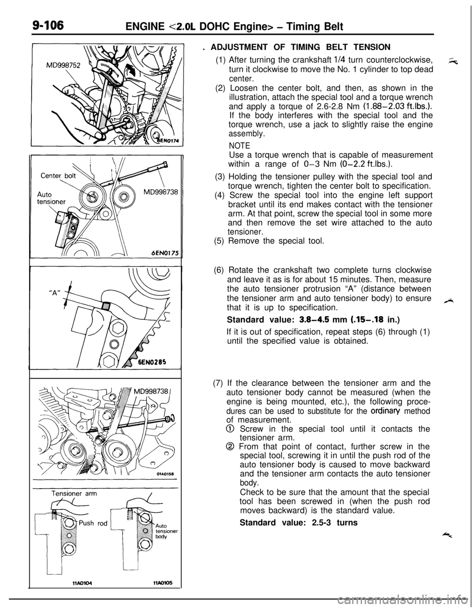
9-106ENGINE <2.0L DOHC Engine> - Timing Belt. ADJUSTMENT OF TIMING BELT TENSION
(1) After turning the crankshaft
l/4 turn counterclockwise,.5;;turn it clockwise to move the No. 1 cylinder to top dead
center.(2) Loosen the center bolt, and then, as shown in the
illustration, attach the special tool and a torque wrench
and apply a torque of 2.6-2.8 Nm
(1.88-2.03 ft.lbs.).If the body interferes with the special tool and the
torque wrench, use a jack to slightly raise the engine
assembly.
NOTEUse a torque wrench that is capable of measurement
within a range of
O-3 Nm (O-2.2 ft.lbs.).(3) Holding the tensioner pulley with the special tool and
torque wrench, tighten the center bolt to specification.
(4) Screw the special tool into the engine left support
bracket until its end makes contact with the tensioner
arm. At that point, screw the special tool in some more
and then remove the set wire attached to the auto
tensioner.(5) Remove the special tool.
(6) Rotate the crankshaft two complete turns clockwise
and leave it as is for about 15 minutes. Then, measure
the auto tensioner protrusion “A” (distance between
the tensioner arm and auto tensioner body) to ensure,.+
that it is up to specification.
Standard value:
3.8-4.5 mm (.15-.18 in.)
If it is out of specification, repeat steps (6) through (1)
until the specified value is obtained.
(7) If the clearance between the tensioner arm and the
auto tensioner body cannot be measured (when the
engine is being mounted, etc.), the following proce-
dures can be used to substitute for the ordinan/ methodof measurement.
@ Screw in the special tool until it contacts the
tensioner arm.
@ From that point of contact, further screw in the
special tool, screwing it in until the push rod of the
auto tensioner body is caused to move backward
and the tensioner arm contacts the auto tensioner
body.Check to be sure that the amount that the special
tool has been screwed in (when the push rod
moves backward) is the standard value.
Standard value: 2.5-3 turns
Page 497 of 1216
FUEL SYSTEM - Service Adjustment Procedures <1.8L Engine>14-43
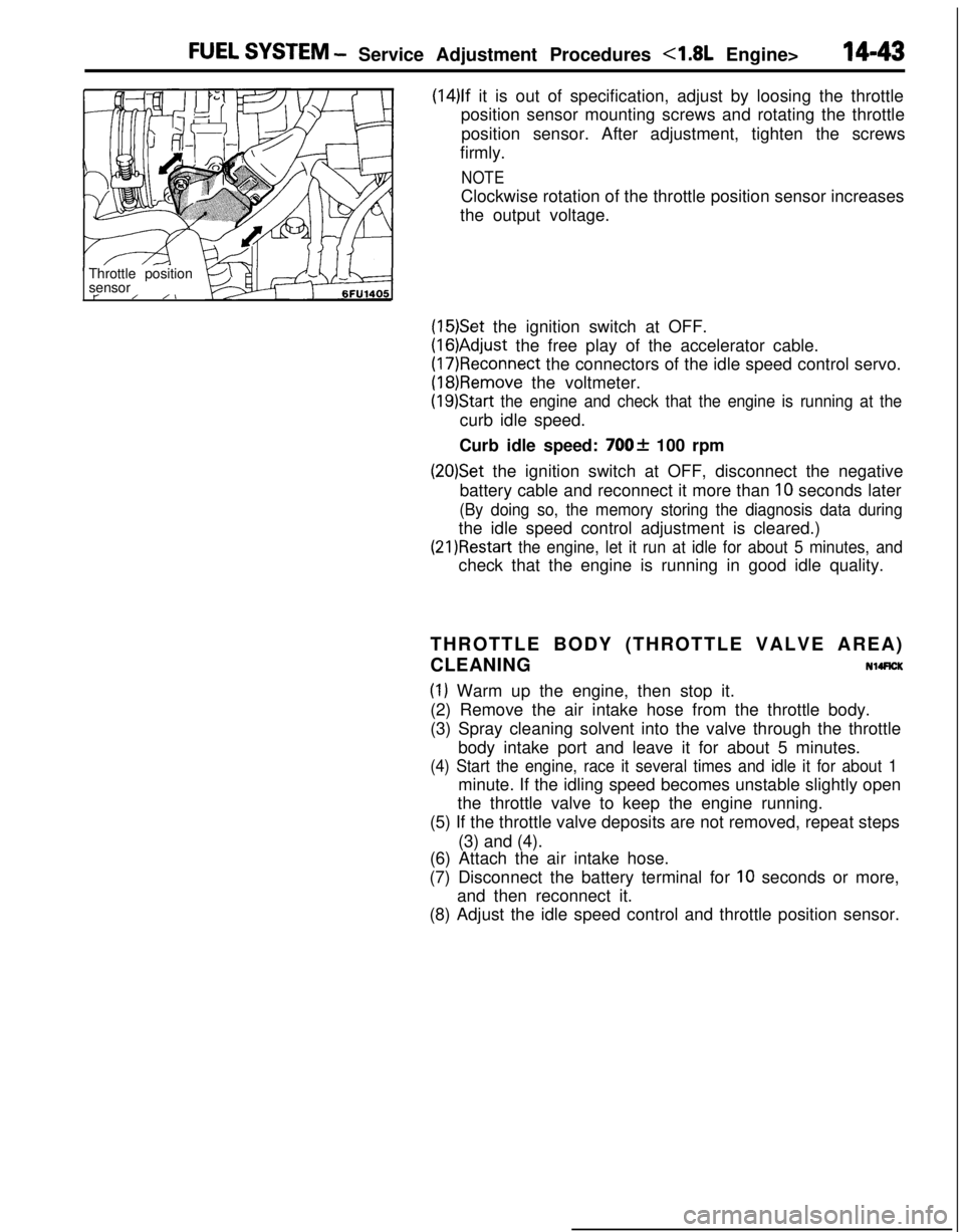
(14)lf it is out of specification, adjust by loosing the throttle
position sensor mounting screws and rotating the throttle
position sensor. After adjustment, tighten the screws
firmly.
NOTEClockwise rotation of the throttle position sensor increases
the output voltage.
Throttle position
sensor
t-/ /I
(15)Set the ignition switch at OFF.
(16)Adjust the free play of the accelerator cable.
(17)Reconnect the connectors of the idle speed control servo.
(18)Remove the voltmeter.
(19)Start the engine and check that the engine is running at thecurb idle speed.
Curb idle speed:
700f 100 rpm
(20)Set the ignition switch at OFF, disconnect the negative
battery cable and reconnect it more than
10 seconds later
(By doing so, the memory storing the diagnosis data duringthe idle speed control adjustment is cleared.)
(21)Restart the engine, let it run at idle for about 5 minutes, andcheck that the engine is running in good idle quality.
THROTTLE BODY (THROTTLE VALVE AREA)
CLEANING
NllRCK
(1) Warm up the engine, then stop it.
(2) Remove the air intake hose from the throttle body.
(3) Spray cleaning solvent into the valve through the throttle
body intake port and leave it for about 5 minutes.
(4) Start the engine, race it several times and idle it for about 1minute. If the idling speed becomes unstable slightly open
the throttle valve to keep the engine running.
(5) If the throttle valve deposits are not removed, repeat steps
(3) and (4).
(6) Attach the air intake hose.
(7) Disconnect the battery terminal for
10 seconds or more,
and then reconnect it.
(8) Adjust the idle speed control and throttle position sensor.
Page 504 of 1216
14-50FUEL SYSTEM - Service Adjustment Procedures <2.0L Engine>THROllLE
POSITION SENSOR ADJUSTME!-T’“.
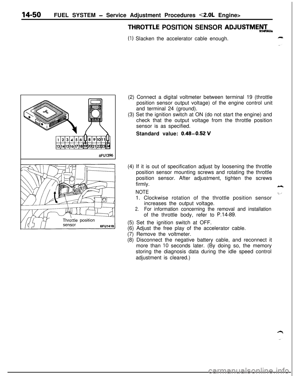
(1) Slacken the accelerator cable enough.
6FU13%(2) Connect a digital voltmeter between terminal 19 (throttle
position sensor output voltage) of the engine control unit
and terminal 24 (ground).
(3) Set the ignition switch at ON (do not start the engine) and
check that the output voltage from the throttle position
sensor is as specified.
Standard value:
0.48-0.52 V(4) If it is out of specification adjust by loosening the throttle
position sensor mounting screws and rotating the throttle
position sensor. After adjustment, tighten the screws
firmly.
NOTE1. Clockwise rotation of the throttle position sensor
increases the output voltage.
2.For information concerning the removal and installationof the throttle body, refer to
P.14-89.(5) Set the ignition switch at OFF.
(6) Adjust the free play of the accelerator cable.
(7) Remove the voltmeter.
(8) Disconnect the negative battery cable, and reconnect it
more than
10 seconds later. (By doing so, the memory
storing the diagnosis data during the idle speed control
adjustment is cleared.)
Page 506 of 1216
14-52FUEL SYSTEM - Service Adjustment Procedures <2.0L Engine>
IDLE POSITION SWITCH ADJUSTMENT
Caution
N14UDAThe idle position switch has been adjusted by the manu-
facturer.Do not, therefore, disturb the setting of the idle-position
switch.
If the setting is disturbed as a result of carelessness, or if
the idle-position switch is replaced, make the necessary
setting as described below.
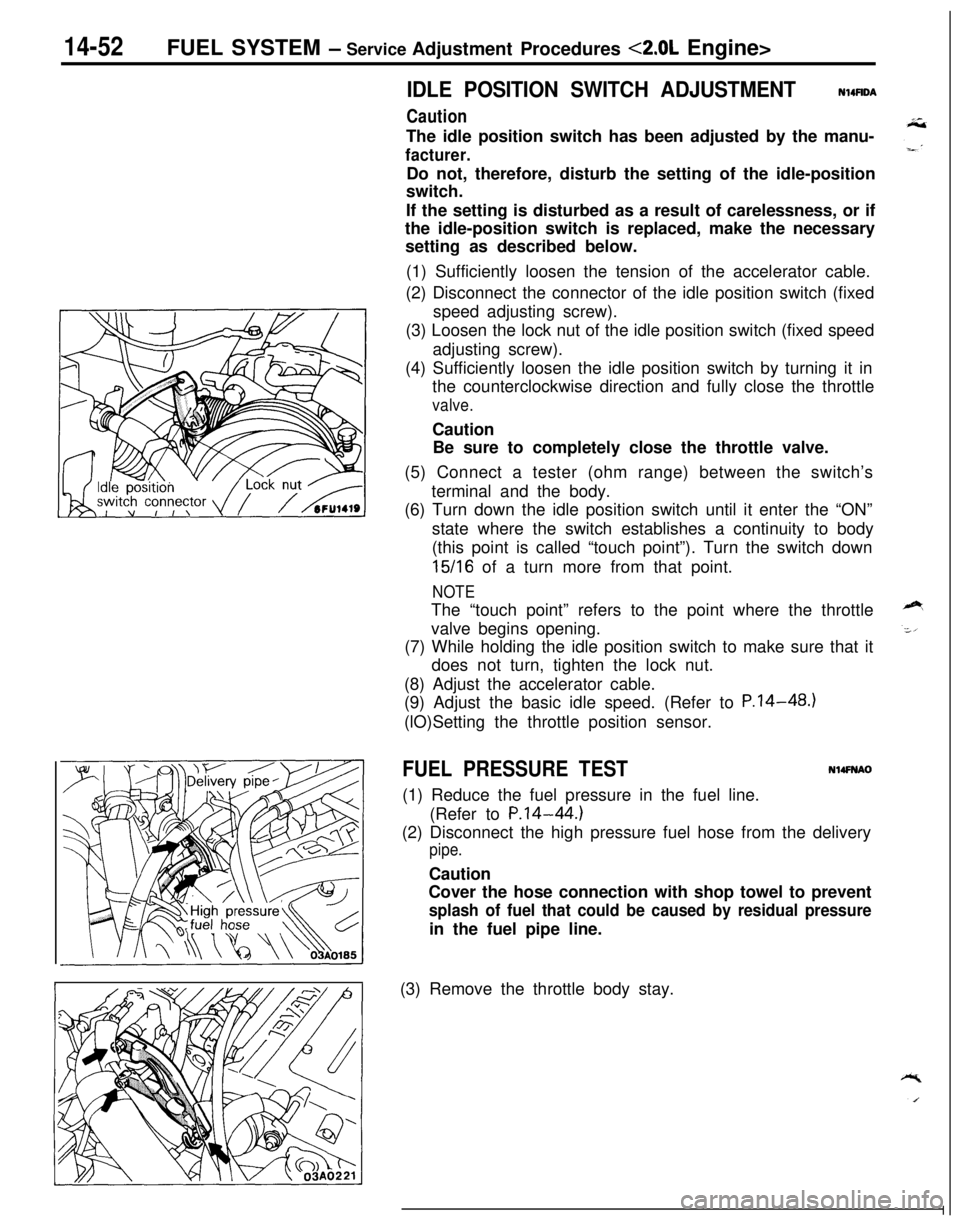
(1) Sufficiently loosen the tension of the accelerator cable.
(2) Disconnect the connector of the idle position switch (fixed
speed adjusting screw).
(3) Loosen the lock nut of the idle position switch (fixed speed
adjusting screw).
(4) Sufficiently loosen the idle position switch by turning it in
the counterclockwise direction and fully close the throttle
valve.Caution
Be sure to completely close the throttle valve.
(5) Connect a tester (ohm range) between the switch’s
terminal and the body.
(6) Turn down the idle position switch until it enter the “ON”
state where the switch establishes a continuity to body
(this point is called “touch point”). Turn the switch down
15/16 of a turn more from that point.
NOTEThe “touch point” refers to the point where the throttle
valve begins opening.
(7) While holding the idle position switch to make sure that it
does not turn, tighten the lock nut.
(8) Adjust the accelerator cable.
(9) Adjust the basic idle speed. (Refer to P.14-48.)
(lO)Setting the throttle position sensor.
FUEL PRESSURE TESTN14FNAO(1) Reduce the fuel pressure in the fuel line.
(Refer to
P.14-44.)(2) Disconnect the high pressure fuel hose from the delivery
pipe.Caution
Cover the hose connection with shop towel to prevent
splash of fuel that could be caused by residual pressurein the fuel pipe line.
(3) Remove the throttle body stay.
Page 674 of 1216
19-26STEERING - Manual Steering Gear Box
Grease
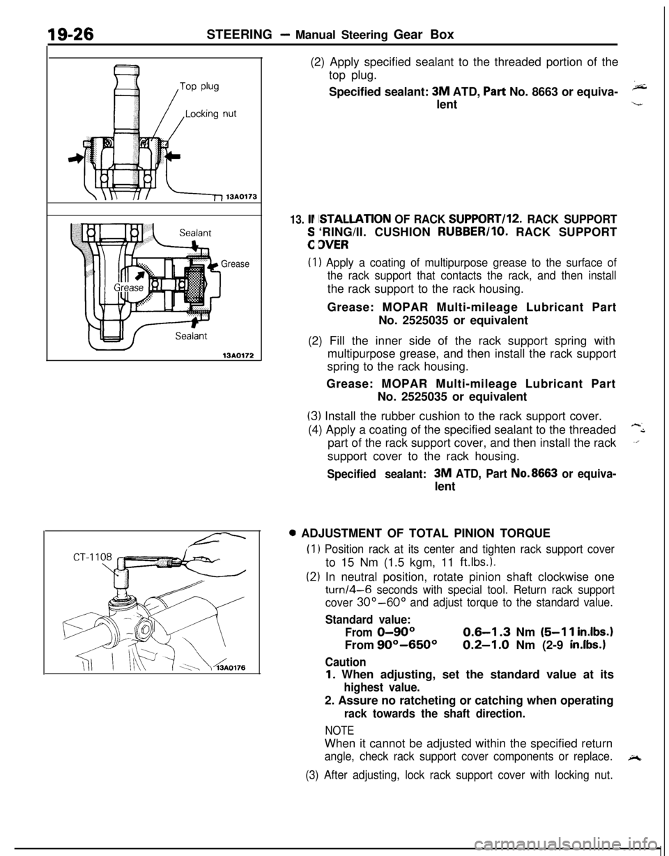
13AO172(2) Apply specified sealant to the threaded portion of the
top plug.
Specified sealant:
3M ATD, Part No. 8663 or equiva-klent
13. lr
:
ISTALLATION OF RACK SUPPORT/l2. RACK SUPPORT‘RING/II. CUSHION RUBBER/IO. RACK SUPPORT
3VER
(I) Apply a coating of multipurpose grease to the surface of
the rack support that contacts the rack, and then installthe rack support to the rack housing.
Grease: MOPAR Multi-mileage Lubricant Part
No. 2525035 or equivalent
(2) Fill the inner side of the rack support spring with
multipurpose grease, and then install the rack support
spring to the rack housing.
Grease: MOPAR Multi-mileage Lubricant Part
No. 2525035 or equivalent
(3) Install the rubber cushion to the rack support cover.
(4) Apply a coating of the specified sealant to the threaded
-Lpart of the rack support cover, and then install the rack
.‘.support cover to the rack housing.
Specified sealant:3M ATD, Part No.8663 or equiva-lent0 ADJUSTMENT OF TOTAL PINION TORQUE
(1
(2
) Position rack at its center and tighten rack support coverto 15 Nm (1.5 kgm, 11
ftlbs.).
:) In neutral position, rotate pinion shaft clockwise one
turn/4-6 seconds with special tool. Return rack support
cover
30”-60” and adjust torque to the standard value.
Standard value:
From
0-90°From
90°-650°
Caution
0.6-I .3 Nm (5-l 1 inIbs.
0.2-1.0 Nm (2-9 in.lbs.1
I. When adjusting, set the standard value at its
highest value.2. Assure no ratcheting or catching when operating
rack towards the shaft direction.
NOTEWhen it cannot be adjusted within the specified return
angle, check rack support cover components or replace.A
(3) After adjusting, lock rack support cover with locking nut.
Page 685 of 1216
STEERING - Power Steering Gear Box
13A017EI
\Silicon grease
Lip
Sealant131564-r-MB990776-A
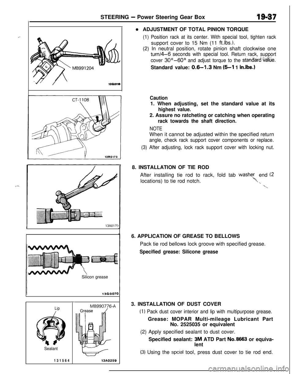
13A0259l ADJUSTMENT OF TOTAL PINION TORQUE
(1) Position rack at its center. With special tool, tighten racksupport cover to 15 Nm (11
ftlbs.).(2) In neutral position, rotate pinion shaft clockwise one
turn/4-6 seconds with special tool. Return rack, support
cover
30°-60° and adjust torque to the stanoard,vaiue.Standard value:
0.6-l .3 Nm (5-l 1 in.lbs.1
Caution1. When adjusting, set the standard value at its
highest value.2. Assure no ratcheting or catching when operating
rack towards the shaft direction.
NOTEWhen it cannot be adjusted within the specified return
angle, check rack support cover components or replace.
(3) After adjusting, lock rack support cover with locking nut.8. INSTALLATION OF TIE ROD
After installing tie rod to rack, fold tab washe;, end (2
locations) to tie rod notch.
‘*,t, \
\6. APPLICATION OF GREASE TO BELLOWS
Pack tie rod bellows lock groove with specified grease.
Specified grease: Silicone grease3. INSTALLATION OF DUST COVER
(1) Pack dust cover interior and lip with multipurpose grease.Grease: MOPAR Multi-mileage Lubricant Part
No. 2525035 or equivalent
(2) Apply specified sealant to dust cover.
Specified sealant: 3M ATD Part
No.8663 or equiva-
lent
(3) Using the spcial tool, press dust cover to tie rod end.
Page 1046 of 1216
23-2
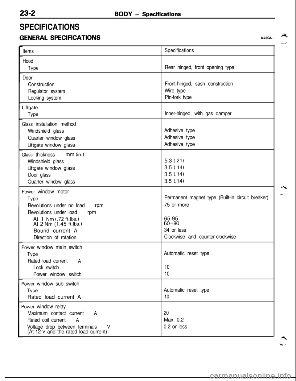
SPECIFICATIONS
GENERAL SPECIFICATIONS
BODY - Specifications
N23CA--
Items
Hood
We
Door
Construction
Regulator system
Locking system
Liftgate
We
Slass installation method
Windshield glass
Quarter window glass
Liftgate window glass
Zlass thicknessmm (in.)
Windshield glass
Liftgate window glass
Door glass
Quarter window glass
‘ower window motor
Type
Revolutions under no loadwm
Revolutions under load
wmAt 1
Nm t.72 ft.lbs.1At 2
Nm (1.45 ft.lbs.1Bound current A
Direction of rotation
‘ower window main switch
Type
Rated load currentA
Lock switch
Power window switch
‘ower window sub switch
TvwRated load current A
‘ower window relay
Maximum contact currentA
Rated coil currentA
Voltage drop between terminalsV(At 12 V and the rated load current)
Specifications
Rear hinged, front opening type
Front-hinged, sash construction
Wire type
Pin-fork type
Inner-hinged, with gas damper
Adhesive type
Adhesive type
Adhesive type5.3
i.21)3.5
t.1413.5
t.1413.5
t.141
Permanent magnet type (Built-in circuit breaker)
75 or more65-95
50-80
34 or less
Clockwise and counter-clockwise
Automatic reset type
10
10
Automatic reset type
10
20
Max. 0.2
0.2 or less
Page 1162 of 1216

24-18 HEATERS AND AIR CONDITIONING - Service Adjustment Procedures
(5) Screw a can of R-12 to the opened manifold valve. Be sure
gasket is in place and in good condition. Tighten refrigerantcan and manifold locking nut to insure a good seal. Do not
overtighten 8 to
11 Nm (6 to 8 ft.lbs.) is sufficient if gasket
is in good condition.
(6) Turn manifold valve (above the refrigerant can) completely
clockwise to puncture the can. This closes the valve and
seals the refrigerant in the can.
Caution
Never heat small cans of refrigerant over
40°C (104°F)as they may explode.
(7) Place the refrigerant in a large pan of water heated to 52°C
(104°F). Place pan of water containing the refrigerant can
on an accurate scale so the amount of refrigerant added
can be weighed. Open the refrigerant manifold valve.
(8) Purge all air from test hoses. Air in the system will be
trapped in the condenser causing abnormally high dis-
charge pressures and interfering with condensing of the
refrigerant.(9) Slightly loosen both test hoses at the gauge set manifold.
Tighten the hoses as soon as the air is purged.
(10)Slightly loosen charging hose connection at gauge set
manifold. This will purge air from the charging hose.
Tighten connection as soon as air is purged.
(I l)With vehicle windows open and hood up, operate engine at1,500 rpm and jump the low pressure switch terminals
located on the receiver drier so the clutch will remain
engaged.
(12)Place air conditioner control on air conditioner and place theblower switch on high.
(13)lf necessary, block the condenser to maintain a discharge
pressure of 1,422 to 1,520
kPa (206 to 220 psi). System
must be charged through the evaporator suction service
ports as follows:
(a) Slowly open the suction service gauge valve.
Meter flow of refrigerant by adjusting, the suciton
service gauge valve so that pressure registered at the
suction service gauge does not exceed 345 kPa (50 psi).Keep refrigerant container upright.
(b) Add refrigerant gas until there is no foam visible at the
sight glass.
Add an additional
170 g (6 oz.)
(c) Close the suction gauge valve.
CautionToo much refrigerant in the system can cause
abnormally high discharge pressures. Care must beused so that the exact recommended amount or
refrigerant is added after foam clears in the sight
glass.(d) Close dispensing manifold valve. Remove test hoses
and adapters from the service ports of compressor,
install protective caps at service ports and reconnect
wiring.(e) Check system performance.
(P.24- 16.)
e
. i”
A
i-4
Page 1165 of 1216
i
HEATERS AND AIR CONDITIONING - Service Adjustment Procedures 24-21Hot water40°C (104°F)
1467CHARGING SYSTEM
The refrigerant system must have been evacuated using the
previous procedure before charging.
Charge using only R-l 2 refrigerant.
R-12 is available in bulk
tanks or small cans. Follow the safety precautions for handling
R-12 as listed in this group.
Charging with Small Cans
When using disposable cans of this type, follow carefully the
can manufacturers instructions.
Caution
Never use these cans to charge into the high pressure side
of the system (compressor discharge port) or into a systemthat is at high temperature, because the high system
pressures could be transferred into the charging can
causing it to explode.
Keep the refrigerant manifold valves capped when not in use.
Keep a supply of extra refrigerant-can-to-refrigerant-manifold
gaskets on hand so that gaskets can be replaced periodically.
This will insure a good seal without excessive tightening of thecan or the manifold nuts.
(1) Attach center hose from manifold gauge set to refrigerant
dispensing manifold. Turn refrigerant manifold valves com-pletely anticlockwise so they are fully open.
Remove protective caps from refrigerant manifold.
(2) Screw refrigerant cans into manifold. Be sure
manifold-to-can gasket is in place and in good condition. Tighten can
and manifold nuts to 8 to 11 Nm (6 to 8
ft.lbs.).(3) Turn refrigerant manifold valves completely clockwise to
puncture the cans and close the manifold valves.
(4) Purge the air from the charging line by loosening the
charging hose at the gauge set manifold and turning one ofthe refrigerant valves anticlockwise to release refrigerant.
When the refrigerant gas starts escaping from the loose
connection, re-tighten the hose.
Caution
Never heat small refrigerant cans over
40°C (104°F) as
they may explode.
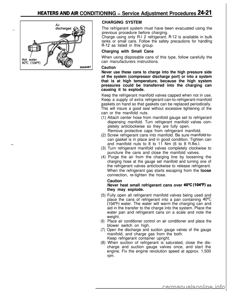
(5) Fully open all refrigerant manifold valves being used and
place the cans of refrigerant into a pan containing
40°C
(104°F) water. The water will warm the charging can and
aid in the transfer to the charge into the system. Place the
water pan and refrigerant cans on a scale and note the
weight.
(6)Place air conditioner control on air conditioner and place theblower switch on high.
(7) Open the discharge and suction gauge valves of the gaugemanifold, and charge gas from the both.
Keep refrigerant container upright.
(8) When suction of refrigerant is saturated, close the dis-
charge and suction gauge valves once, and start the
engine. Fix the engine revolution speed at approx. 1,500
rpm.