spark plugs MITSUBISHI ECLIPSE 1991 Service Manual
[x] Cancel search | Manufacturer: MITSUBISHI, Model Year: 1991, Model line: ECLIPSE, Model: MITSUBISHI ECLIPSE 1991Pages: 1216, PDF Size: 67.42 MB
Page 35 of 1216
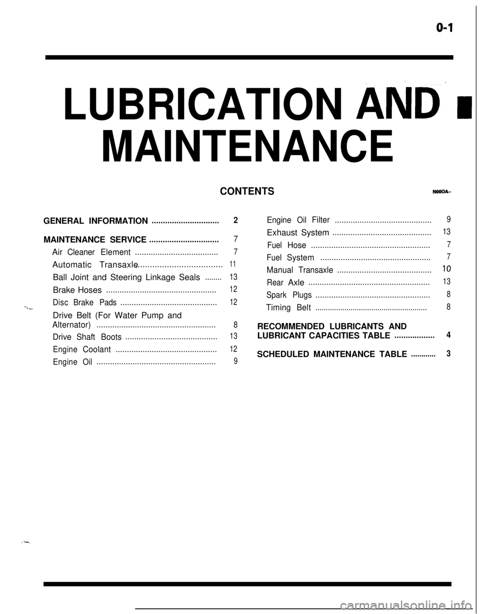
LUBRICATION AND’ I
MAINTENANCE
CONTENTSGENERAL INFORMATION
..............................2MAINTENANCE SERVICE
...............................7Air
CleanerElement.....................................7Automatic Transaxle....................................
11Ball Joint and Steering Linkage Seals
........13Brake Hoses
.................................................12
DiscBrakePads...........................................12-lbDrive Belt (For Water Pump and
Alternator).....................................................8
DriveShaftBoots.........................................13
EngineCoolant.............................................12
EngineOil.....................................................9
EngineOilFilter...........................................9Exhaust System
............................................13
FuelHose.....................................................7
FuelSystem.................................................7
ManualTransaxle..........................................10
RearAxle......................................................13
SparkPlugs...................................................8
TimingBelt......................................................8RECOMMENDED LUBRICANTS AND
LUBRICANT CAPACITIES TABLE
..................4SCHEDULED MAINTENANCE TABLE
............3
Page 37 of 1216
LUBRICATION AND MAINTENANCE - Scheduled MaintenanCe Table. &3
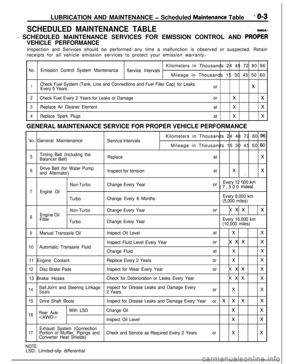
SCHEDULED MAINTENANCE TABLE1
- SCHEDULED MAINTENANCE SERVICES FOR EMISSION CONTROL AND PRO;;
VEHICLE PERFORMANCEInspection and Services should be performed any time a malfunction is observed or suspected. Retain
receipts for all vehicle emission services to protect your emission warranty.
Kilometers in Thousands 24 48 72 80 96
No.Emission Control System Maintenance
Service IntervalsMileage in Thousands 15 30 45 50 60
1Check Fuel System (Tank, Line and Connections and Fuel Filler Cap) for Leaks
Every 5 YearsorX
2Check Fuel Every 2 Years for Leaks or DamageorXX
3Replace Air Cleaner Element
atXX
4Replace Spark Plugs
atXXGENERAL MAINTENANCE SERVICE FOR PROPER VEHICLE PERFORMANCE
Yo. General Maintenance
Service IntervalsKilometers in Thousands 24 48 72 80 9cMileage in Thousands 15 30 45 50
6C
5Timing Belt (Including theBalancer Belt)ReplaceatX
6Drive Belt (for Water Pump
and Alternator)Inspect for tensionatXX.’
Non-TurboChange Every YearEvery 12 000 kmOr (7,500 miles).
7Engine Oil
TurboChange Every 6 MonthsEvery 8,000 km
(5,000 miles)
Non-TurboChange Every Yearor X X XX
8Engine Oil
Filter
TurboChange Every YearEvery 16,000 km
(10,000 miles)
9Manual Transaxle OilInspect Oil LevelatX.X
Inspect Fluid Level Every Yearor X X XX
10Automatic Transaxle Fluid
Change FluidatXX11 Engine Coolant
Replace Every 2 YearsorXX
12Disc Brake PadsInspect for Wear Every Yearor X X XX13 Brake Hoses
Check for Deterioration or Leaks Every YearX X XX
l 4Beiloint and Steering Linkageinspect for Grease Leaks and Damage Every
2 YearsorXX
15Drive Shaft BootsInspect for Grease Leaks and Damage Every Yearor XXXX
Rear Axle
With LSDChange OilXX1 6
Exhaust System (Connection17Portion of Muffler, Pipings andCheck and Service as Required Every 2 Yearsorx -xConverter Heat Shields)
NOTELSD: Limited-slip differential
Page 38 of 1216
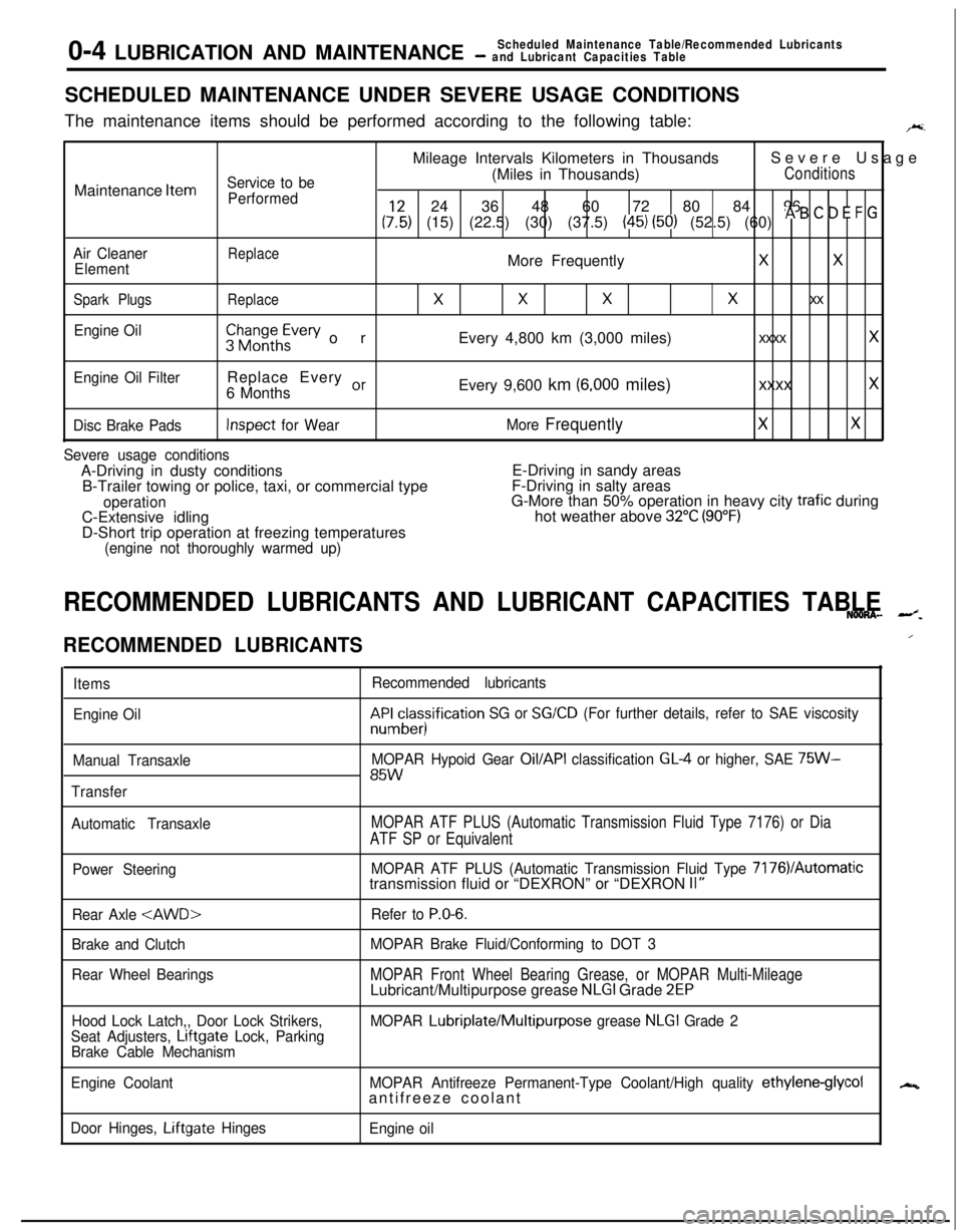
0-4 LUBRICATION AND MAINTENANCEScheduled Maintenance Table/Recommended Lubricants- and Lubricant Capacities TableSCHEDULED MAINTENANCE UNDER SEVERE USAGE CONDITIONS
The maintenance items should be performed according to the following table:
F.Mileage Intervals Kilometers in ThousandsSevere Usage
Service to be(Miles in Thousands)ConditionsMaintenance
Item
Performed24 36 48 60 72 80 84 96
(:,:) (15) (22.5) (30) (37.5) (45) (50) (52.5) (60) * B ’ D E F G
Air CleanerReplaceElementMore FrequentlyXX
Spark PlugsReplace
XXXx xx
Engine Oil$$~~~h~vev orEvery 4,800 km (3,000 miles)xxxx x
Engine Oil FilterReplace Every or6 MonthsEvery 9,600 km (6,000 miles)xxxx x
Disc Brake PadsInspect for WearMore FrequentlyXX
Severe usage conditionsA-Driving in dusty conditionsE-Driving in sandy areas
B-Trailer towing or police, taxi, or commercial typeF-Driving in salty areas
operationG-More than 50% operation in heavy city trafic during
C-Extensive idlinghot weather above 32°C (90°F)D-Short trip operation at freezing temperatures
(engine not thoroughly warmed up)
RECOMMENDED LUBRICANTS AND LUBRICANT CAPACITIES TABLENOONA- --z.
RECOMMENDED LUBRICANTS
Items
Engine Oil
Manual Transaxle
TransferRecommended lubricantskF&cesisification
SG or SG/CD (For further details, refer to SAE viscosity
MOPAR Hypoid Gear
Oil/API classification GL4 or higher, SAE 75W-85W
Automatic TransaxleMOPAR ATF PLUS (Automatic Transmission Fluid Type 7176) or Dia
ATF SP or Equivalent
Power SteeringMOPAR ATF PLUS (Automatic Transmission Fluid Type 7176VAutomatictransmission fluid or “DEXRON” or “DEXRON II”
Rear Axle
Brake and Clutch
Rear Wheel BearingsRefer to
P.O-6.
MOPAR Brake Fluid/Conforming to DOT 3
MOPAR Front Wheel Bearing Grease, or MOPAR Multi-MileageLubricant/Multipurpose grease NLGI Grade 2EP
Hood Lock Latch,, Door Lock Strikers,
Seat Adjusters, Lrftgate Lock, Parking
Brake Cable MechanismMOPAR Lubriplate/Multipurpose grease NLGI Grade 2
Engine CoolantMOPAR Antifreeze Permanent-Type Coolant/High quality
ethylene-glycolantifreeze coolant
Door Hinges, Liftgate Hinges
Engine oil
/
N
Page 42 of 1216
O-8LUBRICATION AND MAINTENANCE - Maintenance Service
0-L
I-TOlLO182
-
, ,6COOO9
u6COO394. SPARK PLUGS (Replace)
NOOSAOFa1. Spark plugs must spark properly to assure proper
~engine performance and reduce exhaust emission
level.Therefore, they should be replaced periodically with
new ones.
2. The new plugs should be checked for the proper gap.
Spark plug gap
1.0-1.1 mm (.039-.043 in.)
0.7-0.8 mm (.028-.031 in.)
3.Install the spark plug and tighten to 20-30 Nm (15-21
ft.lbs.).5. TIMING BELT (Replace)
NOOSBACaReplace the belt with a new one periodically to assure
proper engine performance.
For removal and installation procedures, refer to GROUP
g-Timing Belt.
6. DRIVE BELT (For Water
Pump and Alternator)
(Inspect for tension)
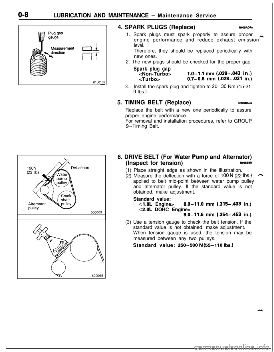
NOOSSBN(1) Place straight edge as shown in the illustration.
(2) Measure the deflection with a force of
100 N (22 Ibs.)rzapplied to belt mid-point between water pump pulley
-and alternator pulley. If the standard value is not
obtained, make adjustment.
Standard value:
<1.8L Engine>8.0-11.0 mm (.315-A33 in.)
<2.0L DOHC Engine>
9.0-11.5 mm (.354-.453 in.)
(3) Use a tension gauge to check the belt tension. If the
standard value is not obtained, make adjustment.
When tension gauge is used, the tension may be
measured between any two pulleys.
Standard value:
250-500 N (55-110 Ibs.)
Page 308 of 1216
9-24ENGINE - Service Adjustment Procedures
ENGINE 4.8L Engine>
SERVICE ADJUSTMENT PROCEDURES -
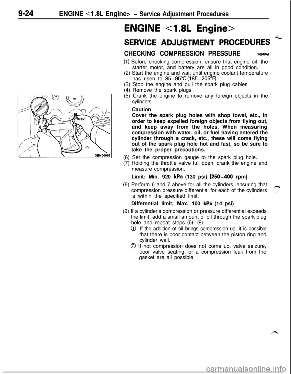
CHECKING COMPRESSION PRESSURENOSFFAI
(1) Before checking compression, ensure that engine oil, the
starter motor, and battery are all in good condition.
(2) Start the engine and wait until engine coolant temperature
has risen to
85-95°C (185-205°F).
(3) Stop the engine and pull the spark plug cables.
(4) Remove the spark plugs.
(5) Crank the engine to remove any foreign objects in the
cylinders.Caution
Cover the spark plug holes with shop towel, etc., in
order to keep expelled foreign objects from flying out,
and keep away from the holes. When measuring
compression with water, oil, or fuel having entered the
cylinder through a crack, etc., these will come flying
out of the spark plug hole hot and fast, so be sure to
take the proper precautions.
(6) Set the compression gauge to the spark plug hole.
(7) Holding the throttle valve full open, crank the engine and
measure compression.
Limit: Min. 920
kPa (130 psi) [250-400 rpm]
(8) Perform 6 and 7 above for all the cylinders, ensuring that
compression pressure differential for each of the cylinders
/Iis within the specified limit.
__Differential limit: Max. 100
kPa (14 psi)
(9) If a cylinder’s compression or pressure differential exceeds
the limit, add a small amount of oil through the spark plug
hole and repeat steps (6)-(8).
0If the addition of oil brings compression up, it is possiblethat there is poor contact between the piston ring and
cylinder wall.
@ If not compression does not come up, valve seizure,
poor valve seating, or a compression leak from the
gasket are all possible.
/y
-
Page 310 of 1216
9-26ENGINE <1.8L Engine> -Service Adjustment Procedures
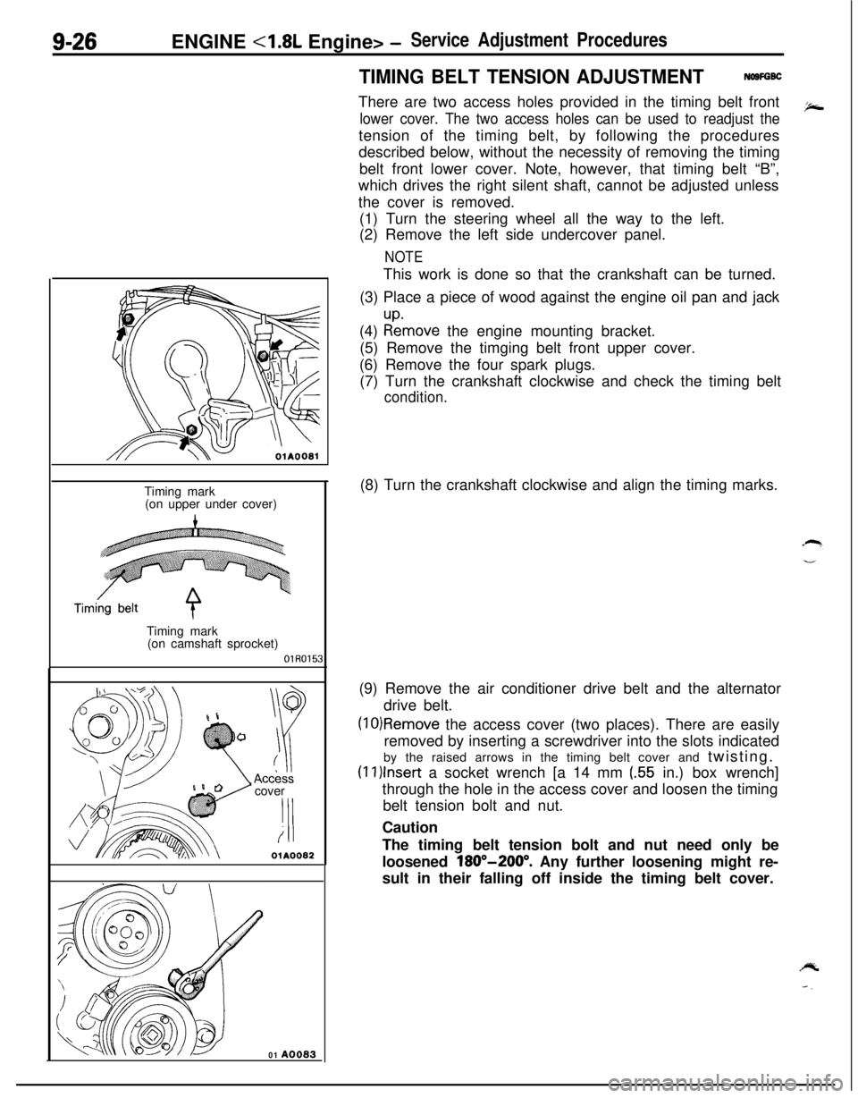
TIMING BELT TENSION ADJUSTMENTNOSFGBCThere are two access holes provided in the timing belt front
lower cover. The two access holes can be used to readjust thetension of the timing belt, by following the procedures
described below, without the necessity of removing the timing
belt front lower cover. Note, however, that timing belt “B”,
which drives the right silent shaft, cannot be adjusted unless
the cover is removed.
(1) Turn the steering wheel all the way to the left.
(2) Remove the left side undercover panel.
NOTEThis work is done so that the crankshaft can be turned.
(3) Place a piece of wood against the engine oil pan and jack
(4)
:tmove the engine mounting bracket.
(5) Remove the timging belt front upper cover.
(6) Remove the four spark plugs.
(7) Turn the crankshaft clockwise and check the timing belt
condition.
OlAOOBlTiming mark
(on upper under cover)
Timing mark
(on camshaft sprocket)
OlR0153cover
‘I!i
OlA0082
01 A0083(8) Turn the crankshaft clockwise and align the timing marks.
(9) Remove the air conditioner drive belt and the alternator
drive belt.
(10)Remove the access cover (two places). There are easily
removed by inserting a screwdriver into the slots indicated
by the raised arrows in the timing belt cover and twisting.
(1l)lnser-t a socket wrench [a 14 mm (.55 in.) box wrench]
through the hole in the access cover and loosen the timing
belt tension bolt and nut.
Caution
The timing belt tension bolt and nut need only be
loosened
180”-200”. Any further loosening might re-
sult in their falling off inside the timing belt cover.
Page 311 of 1216
ENGINE <1.8L Engine> -Service Adjustment Procedures9-27
I.
Timing mark(on upper under cover)Timing belt
Timing mark
A(on camshaft
sprocket)OlR0154
3EN076
3EN07;-
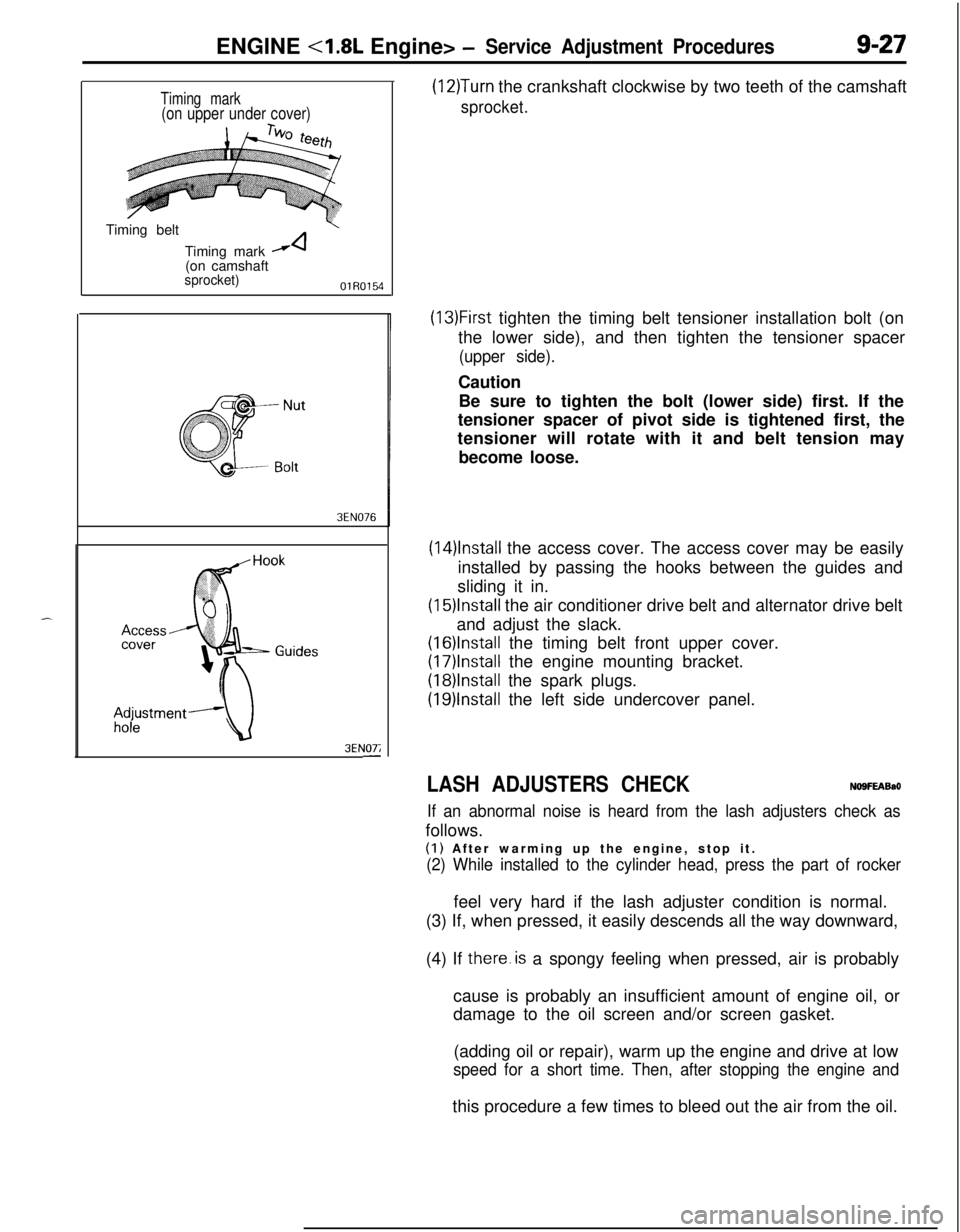
(12)Turn the crankshaft clockwise by two teeth of the camshaft
sprocket.
(13)First tighten the timing belt tensioner installation bolt (on
the lower side), and then tighten the tensioner spacer
(upper side).Caution
Be sure to tighten the bolt (lower side) first. If the
tensioner spacer of pivot side is tightened first, the
tensioner will rotate with it and belt tension may
become loose.
(14)lnstall the access cover. The access cover may be easily
installed by passing the hooks between the guides and
sliding it in.
(15)lnstall the air conditioner drive belt and alternator drive belt
and adjust the slack.
(16)lnstalI the timing belt front upper cover.
(17)lnstall the engine mounting bracket.
(18)lnstalI the spark plugs.
(19)lnstall the left side undercover panel.
LASH ADJUSTERS CHECKNO9FEABaO
If an abnormal noise is heard from the lash adjusters check asfollows.
(I) After warming up the engine, stop it.
(2) While installed to the cylinder head, press the part of rockerfeel very hard if the lash adjuster condition is normal.
(3) If, when pressed, it easily descends all the way downward,
(4) If there.is a spongy feeling when pressed, air is probably
cause is probably an insufficient amount of engine oil, or
damage to the oil screen and/or screen gasket.
(adding oil or repair), warm up the engine and drive at low
speed for a short time. Then, after stopping the engine andthis procedure a few times to bleed out the air from the oil.
Page 358 of 1216
9-74ENGINE <2.0L DOHC Engine>- Service Adjustment Procedures
ENGINE <2.0L DOHC Engine>
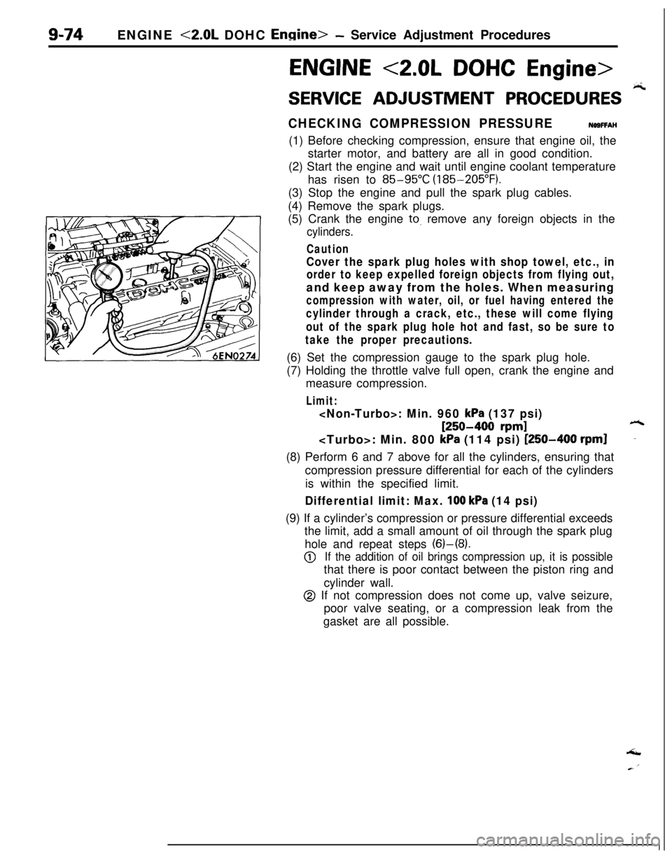
SERVICE ADJUSTMENT PROCEDURES pi
CHECKING COMPRESSION PRESSURENOSFFAH(1) Before checking compression, ensure that engine oil, the
starter motor, and battery are all in good condition.
(2) Start the engine and wait until engine coolant temperature
has risen to
85-95°C (185-205°F).
(3) Stop the engine and pull the spark plug cables.
(4) Remove the spark plugs.
(5) Crank the engine
to. remove any foreign objects in the
cylinders.
Caution
Cover the spark plug holes with shop towel, etc., in
order to keep expelled foreign objects from flying out,and keep away from the holes. When measuring
compression with water, oil, or fuel having entered the
cylinder through a crack, etc., these will come flying
out of the spark plug hole hot and fast, so be sure to
take the proper precautions.(6) Set the compression gauge to the spark plug hole.
(7) Holding the throttle valve full open, crank the engine and
measure compression.
Limit:
[250-400 rpm]6
kPa (114 psi) [250-400 rpml-(8) Perform 6 and 7 above for all the cylinders, ensuring that
compression pressure differential for each of the cylinders
is within the specified limit.
Differential limit: Max. 100 kPa (14 psi)(9) If a cylinder’s compression or pressure differential exceeds
the limit, add a small amount of oil through the spark plug
hole and repeat steps (6)-(8).
@If the addition of oil brings compression up, it is possiblethat there is poor contact between the piston ring and
cylinder wall.
@ If not compression does not come up, valve seizure,
poor valve seating, or a compression leak from the
gasket are all possible.‘I
Page 460 of 1216
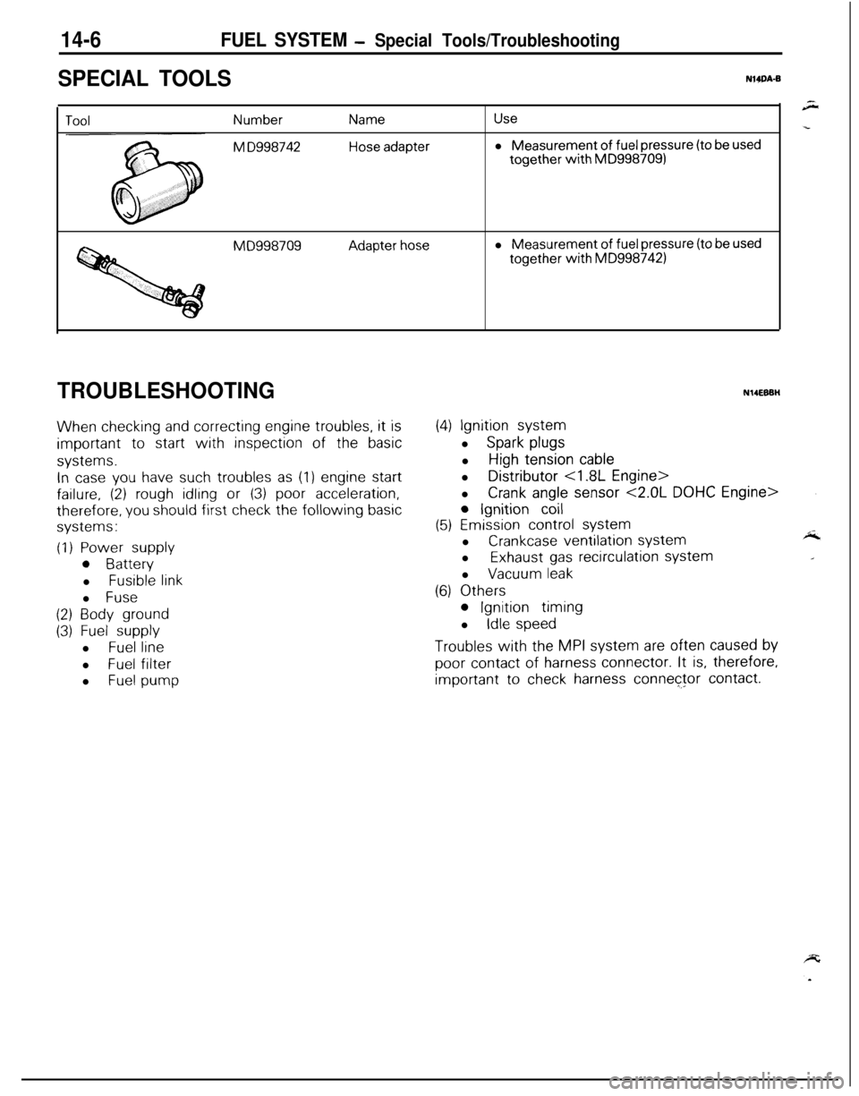
14-6FUEL SYSTEM - Special Tools/Troubleshooting
SPECIAL TOOLSNWA-B
Number
M D998742
Name
Hose adapter
Usel Measurement
of fuel pressure (to be usedtogether
with MD9987091
MD998709Adapter hosel Measurement of fuel pressure (to be usedtogether
with MD9987421
TROUBLESHOOTING
When checking and correcting engine troubles, it is
important to start with inspection of the basic
systems.
In case you have such troubles as (1) engine start
failure, (2) rough idling or (3) poor acceleration,
therefore, you should first check the following basic
systems:
(1) Power supply
0 Batteryl
Fusible linkl
Fuse
(2) Body ground
(3) Fuel supplyl
Fuel linel
Fuel filter
l
Fuel pump
N14EBBH
(4) Ignition systeml
Spark plugsl
High tension cablel Distributor
<1.8L Engine>
l
Crank angle sensor <2.0L DOHC Engine>
0 Ignition coil
(5) Emission control systeml
Crankcase ventilation systeml
Exhaust gas recirculation systeml
Vacuum leak
(6) Others
0 Ignition timing
l
Idle speed
Troubles with the MPI system are often caused by
poor contact of harness connector. It is, therefore,
important to check harness connector contact.