Wiring diagram MITSUBISHI ENDEAVOR 2004 Service Repair Manual
[x] Cancel search | Manufacturer: MITSUBISHI, Model Year: 2004, Model line: ENDEAVOR, Model: MITSUBISHI ENDEAVOR 2004Pages: 3870, PDF Size: 98.47 MB
Page 232 of 3870
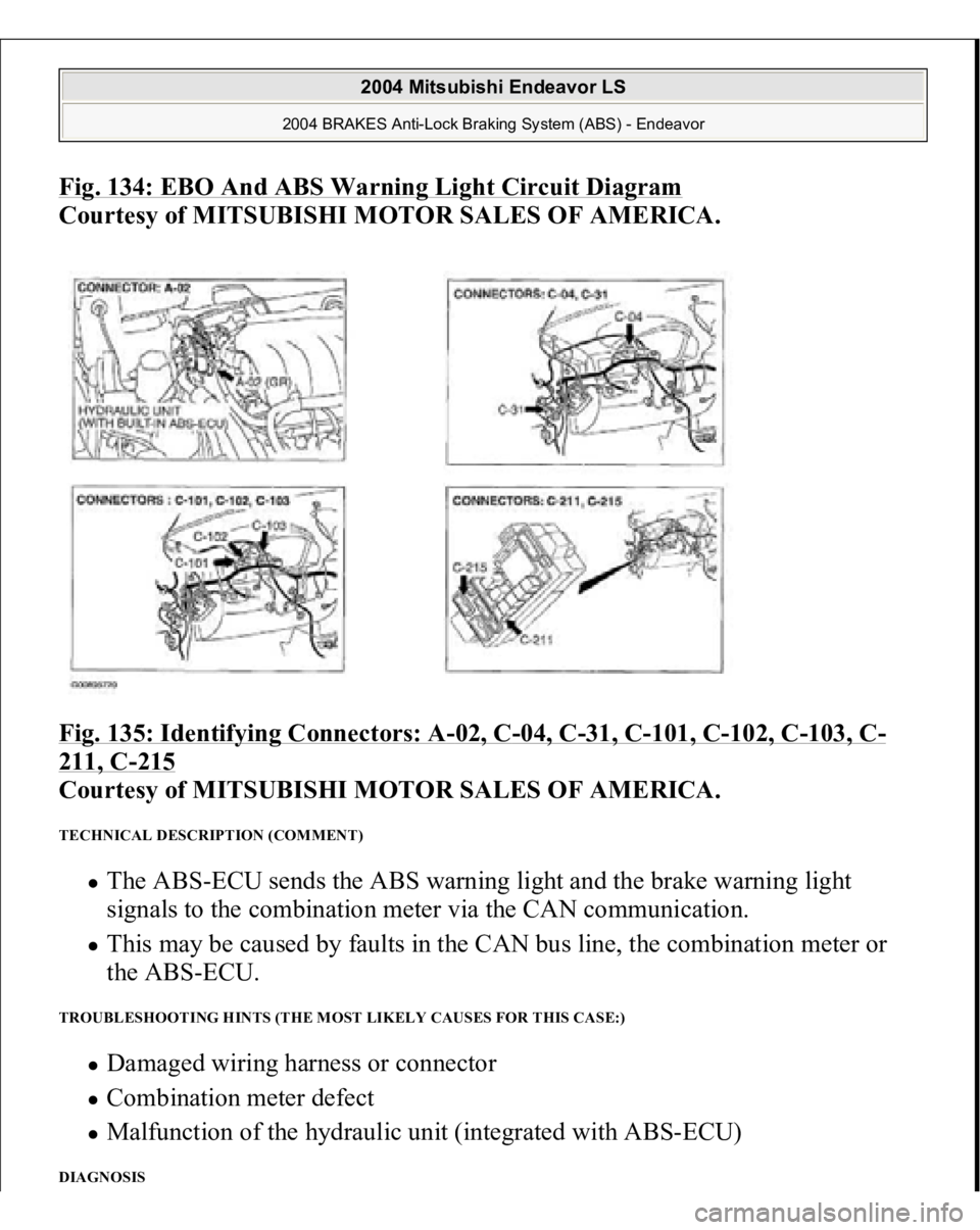
Fig. 134: EBO And ABS Warning Light Circuit Diagram
Courtesy of MITSUBISHI MOTOR SALES OF AMERICA.
Fig. 135: Identifying Connectors: A
-02, C
-04, C
-31, C
-101, C
-102, C
-103, C
-
211, C
-215
Courtesy of MITSUBISHI MOTOR SALES OF AMERICA.
TECHNICAL DESCRIPTION (COMMENT)
The ABS-ECU sends the ABS warning light and the brake warning light
signals to the combination meter via the CAN communication. This may be caused by faults in the CAN bus line, the combination meter or
the ABS-ECU.
TROUBLESHOOTING HINTS (THE MOST LIKELY CAUSES FOR THIS CASE:)
Damaged wiring harness or connector Combination meter defect Malfunction of the hydraulic unit (integrated with ABS-ECU)
DIAGNOSIS
2004 Mitsubishi Endeavor LS
2004 BRAKES Anti-Lock Braking System (ABS) - Endeavor
Page 278 of 3870
On-vehicle Deployment 1. Before proceeding, see
AIR BAG SAFETY PRECAUTIONS
. Move vehicle
to an isolated area. Open all doors and windows. Disconnect and shield
negative battery cable end. Disconnect positive battery cable. Remove battery
from vehicle. Wait at least 60 seconds before continuing.
2. To deploy driver-side air bag module, remove steering column lower cover.
Disconnect lower clockspring Yellow 4-pin connector. Cut harness side of
connector from wire harness and strip ends of driver-side air bag module wires
on harness side of clockspring connector. See
WIRING DIAGRAMS
.
3. To deploy passenger-side air bag module, remove glove box and glove box
outer case. Disconnect passenger-side air bag module Red connector.
4. To deploy side impact air bag module, disconnect appropriate side impact air
bag module Red connector, located under front seat.
5. To deploy seat belt pretensioner, disconnect appropriate seat belt pretensioner
connector, located at seat belt pretensioner.
6. Fabricate a de
ployment harness usin
g two wires at least 20 feet
(6.1 m
) in
WARNING:Air bag modules and seat belt pretensioners make
loud noises during deployment. Air bag module and
seat belt pretensioner deployment could cause
personal injury. Always deploy components
outdoors and away from people. Never deploy air
bag modules with trim cover face down.
NOTE: If vehicle is to be scrapped, perform On-vehicle
deployment. See ON
-VEHICLE DEPLOYMENT
. If vehicle
will continue to be operated, perform Off-vehicle
Deployment. See OFF
-VEHICLE DEPLOYMENT
.
NOTE: Driver-side and passenger-side air bag modules will be
either single-stage or dual-stage. Consult wiring
diagrams to ensure correct wires are cut and spliced
prior to deployment. See WIRING DIAGRAMS
.
2004 Mitsubishi Endeavor Limited
2004 ACCESSORIES/SAFETY EQUIPMENT Mitsubishi - Air Bag Restraint Systems
Page 279 of 3870
length. Strip insulation from ends of wires. Connect wires at one end of harness
to clockspring connector stripped wires and cover connections with insulating
tape. Temporarily wrap other end of harness wires together to prevent
unexpected air bag deployment.
7. Stretch deployment harness as far away from vehicle as possible. Roll up
vehicle windows to lessen deployment noise and cover vehicle with car cover,
in case glass should shatter during deployment. Ensure area is clear of people.
Untwist deployment harness wire ends. Touch wire ends to 12 volt battery
terminals to deploy driver-side air bag module.
8. Repeat procedure for remaining air bag modules and seat belt pretensioners.
Use SRS Air Bag Adapter Harness (MB686560) for passenger-side and side
impact air bag modules. Use SRS Adapter Harness (MR991885) for seat belt
pretensioners. If any component fails to deploy, stay away from vehicle and
contact manufacturer for further instructions. Allow 30 minutes for air bag
modules to cool.
Off-vehicle Deployment 1. Before proceeding, see
AIR BAG SAFETY PRECAUTIONS
. Turn ignition
switch to LOCK position. Disconnect negative battery cable. Shield cable end.
Wait at least 60 seconds before continuing. Disconnect positive battery cable.
Remove battery from vehicle.
2. Fabricate a deployment harness using two wires at least 20 feet (6.1 m) in
length. Strip insulation from ends of wires. Twist together one end of wires
temporarily. Remove driver-side air bag module. See
DRIVER
-SIDE AIR
BAG MODULE & CLOCKSPRING
under REMOVAL &
INSTALLATION. Place driver-side air bag module on surface face up. Touch
vehicle body with bare hands to discharge static electricity from body. Cut
driver-side air bag module connector from pigtail leads. Strip insulation from
ends of
pigtail wires. Attach remainin
g ends of de
ployment harness to
pigtail NOTE: Driver-side and passenger-side air bag modules will be
either single-stage or dual-stage. Consult wiring
diagrams to ensure correct wires are cut and spliced
prior to deployment. See WIRING DIAGRAMS
.
2004 Mitsubishi Endeavor Limited
2004 ACCESSORIES/SAFETY EQUIPMENT Mitsubishi - Air Bag Restraint Systems
Page 309 of 3870
DIAGNOSTIC TESTS INSPECTION PROCEDURE 1 No communication between scan tool and all systems is most likely in power
supply or ground circuits to Data Link Connector (DLC). Check wire harness and
connectors for damage and loose connections. See WIRING DIAGRAMS
.
INSPECTION PROCEDURE 2 1. Before proceeding, see AIR BAG SAFETY PRECAUTIONS
. Disconnect
SRS ECU connector C-26. See SRS ELECTRONIC CONTROL UNIT
(SRS ECU)
under REMOVAL & INSTALLATION. See Fig. 19
. Measure
resistance between SRS ECU connector C-26, terminal No. 20 (Orange/Blue
wire) and Data Link Connector (DLC), terminal No. 7 (Orange/Blue wire). See
Fig. 20
& Fig. 21
. If resistance is more than 2 ohms, go to next step. If
resistance is 2 ohms or less, go to step 4 .
2. Measure resistance between SRS ECU connector C-26, terminal No. 15 (Black
wire) and ground. If resistance is less than 2 ohms, go to next step. If resistance
is 2 ohms or more, go to step 5 .
3. Connect negative battery cable. Turn ignition on. Measure voltage between
ground and SRS ECU connector C-26, terminals No. 13 (Black/White wire)
and No. 16 (Black/Yellow wire). If voltage is less than 9 volts at either
terminal, go to step 6 . If voltage at both terminals is 9 volts or more, recheck
trouble s
ymptom. If s
ymptom still exists, re
place SRS ECU. Go to ste
p 7 .
B1547
Cut off for passenger-side air bag module
B1552
Changing circuit short
B1553
Changing circuit open
B1554
SG by-pass circuit malfunction
B1555
SG by-pass circuit (FET) open
B1556
Seat slide sensor malfunction
B1557
SRS ECU ASIC
B1558
Occupant classification ECU ID cord malfunction
U1073
BUS of
f
2004 Mitsubishi Endeavor Limited
2004 ACCESSORIES/SAFETY EQUIPMENT Mitsubishi - Air Bag Restraint Systems
Page 327 of 3870
with fuse No. 23. See WIRING DIAGRAMS
. If continuity does not exist, go
to next step.
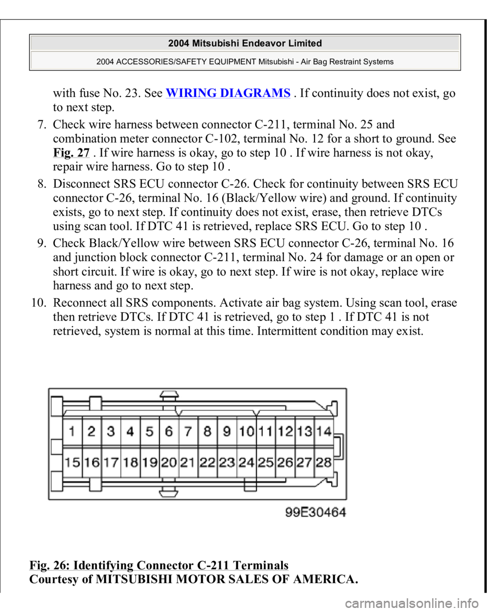
7. Check wire harness between connector C-211, terminal No. 25 and
combination meter connector C-102, terminal No. 12 for a short to ground. See
Fig. 27
. If wire harness is okay, go to step 10 . If wire harness is not okay,
repair wire harness. Go to step 10 .
8. Disconnect SRS ECU connector C-26. Check for continuity between SRS ECU
connector C-26, terminal No. 16 (Black/Yellow wire) and ground. If continuity
exists, go to next step. If continuity does not exist, erase, then retrieve DTCs
using scan tool. If DTC 41 is retrieved, replace SRS ECU. Go to step 10 .
9. Check Black/Yellow wire between SRS ECU connector C-26, terminal No. 16
and junction block connector C-211, terminal No. 24 for damage or an open or
short circuit. If wire is okay, go to next step. If wire is not okay, replace wire
harness and go to next step.
10. Reconnect all SRS components. Activate air bag system. Using scan tool, erase
then retrieve DTCs. If DTC 41 is retrieved, go to step 1 . If DTC 41 is not
retrieved, system is normal at this time. Intermittent condition may exist.
Fig. 26: Identifying Connector C
-211 Terminals
Courtesy of MITSUBISHI MOTOR SALES OF AMERICA.
2004 Mitsubishi Endeavor Limited
2004 ACCESSORIES/SAFETY EQUIPMENT Mitsubishi - Air Bag Restraint Systems
Page 396 of 3870
next step. If DTC B1477 is not retrieved, an intermittent condition may exist.
3. Remove fuse No. 23 from instrument panel junction block. See Fig. 39
. If fuse
is blown, go to step 6 . If fuse is not blown, go to next step.
4. Disconnect negative battery cable. Disconnect SRS ECU connector C-26. See
SRS ELECTRONIC CONTROL UNIT (SRS ECU)
under REMOVAL &
INSTALLATION. See Fig. 30
. Connect negative battery cable. Turn ignition
on. Measure voltage between ground and SRS ECU connector C-26, terminal
No. 24 (Black/Yellow wire). If voltage is 9 volts or more, reconnect SRS
components. Erase, then retrieve DTCs. If DTC B1477 is retrieved, replace
SRS ECU. Go to step 8 . If DTC B1477 is not retrieved, go to next step.
5. Inspect Black/Yellow wire between SRS ECU connector C-26, terminal No. 24
and ignition switch connector C-308, terminal No. 2. See WIRING
DIAGRAMS
. If wire is okay, go to step 8 . If wire is not okay, replace
harness between SRS ECU and ignition switch. Go to step 8 .
6. Replace fuse. Turn ignition on for one minute, then turn off. Inspect fuse. If
fuse is okay, go to step 8 . If fuse is not okay, go to next step.
7. Measure resistance between SRS ECU connector terminal No. 24 and ground.
If zero ohms is measured, inspect all circuits running from fuse No. 23 for a
short to ground. including connector C-211. See Fig. 22
. Repair short to
ground. See WIRE REPAIR
. Go to next step. If continuity does not exist,
reconnect SRS components. Erase, then retrieve DTCs. If DTC B1477 is
retrieved, replace SRS ECU. Go to next step.
8. Reconnect all SRS components. Activate air bag system. Using scan tool,
retrieve DTCs. If DTC B1473 is retrieved, go to step 1 . If DTC B1473 is not
retrieved, system is normal at this time.
DTC B1478: SRS ECU CAPACITOR CIRCUIT VOLTAGE HIGH 1. Connect scan tool to Data Link Connector (DLC). See INITIAL SRS
DIAGNOSTIC PROCEDURE
under DIAGNOSTICS. If scan tool is able to
diagnose CAN bus lines and CAN bus lines are satisfactory, go to next step. If
scan tool cannot diagnose CAN bus lines, repair CAN bus lines. Go to next
step.
2. Erase, then retrieve DTCs. If DTC B1478 is retrieved, replace SRS ECU. See
SRS ELECTRONIC CONTROL UNIT (SRS ECU)
under REMOVAL &
2004 Mitsubishi Endeavor Limited
2004 ACCESSORIES/SAFETY EQUIPMENT Mitsubishi - Air Bag Restraint Systems
Page 445 of 3870
6 . If ACCURACY CHECK COMPLETION is not displayed, go to next step.
5. If ABNORMAL CONDITION is displayed, press OK and go to calibration
screen. Remove weight from seat. Verify seat is installed correctly. If seat is
installed correctly, go to step 1 .
6. Remove weight from seat cushion. Move seat to rear most position. Repeat
step2 . Go to next step.
7. Select INTERACTIVE DIAGNOSIS, then SPECIAL FUNCTION then SEAT
WEIGHT SENSOR ACCURACY CHECK on screen. Place a 66 pound weight
(30 kg) in center of passenger-side seat cushion. Repeat step2 . Touch OK
button to perform accuracy check. Go to next step.
8. If variance between sensor output and input levels is within 11 pounds (5 kg),
ACCURACY CHECK COMPLETION will be displayed on screen.
Calibration is complete. If ACCURACY CHECK COMPLETION is not
displayed, go to next step.
9. Verify seat is installed correctly. Repeat step2 . Touch OK button. When
EXECUTION prompt is displayed, touch OK button. When calibration is
completed, screen will display ZERO CALIBRATION COMPLETED. If
calibration cannot be completed, an intermittent condition may exist.
FRONT IMPACT SENSOR (DUAL-STAGE AIR BAG SYSTEM) 1. Remove appropriate front impact sensor. See FRONT IMPACT SENSOR
under REMOVAL & INSTALLATION. Visually inspect front impact sensor
case, connectors and brackets for damage. If no damage is found, go to next
step. If damage is found, discard front impact sensor.
2. Measure resistance between terminals of front impact sensor. Resistance
should be 738-902 ohms. Measure resistance between front impact sensor
terminals and front impact sensor case. Resistance should be infinite. If
resistance is not as specified, replace front impact sensor.
WIRING DIAGRAMS
2004 Mitsubishi Endeavor Limited
2004 ACCESSORIES/SAFETY EQUIPMENT Mitsubishi - Air Bag Restraint Systems
Page 810 of 3870
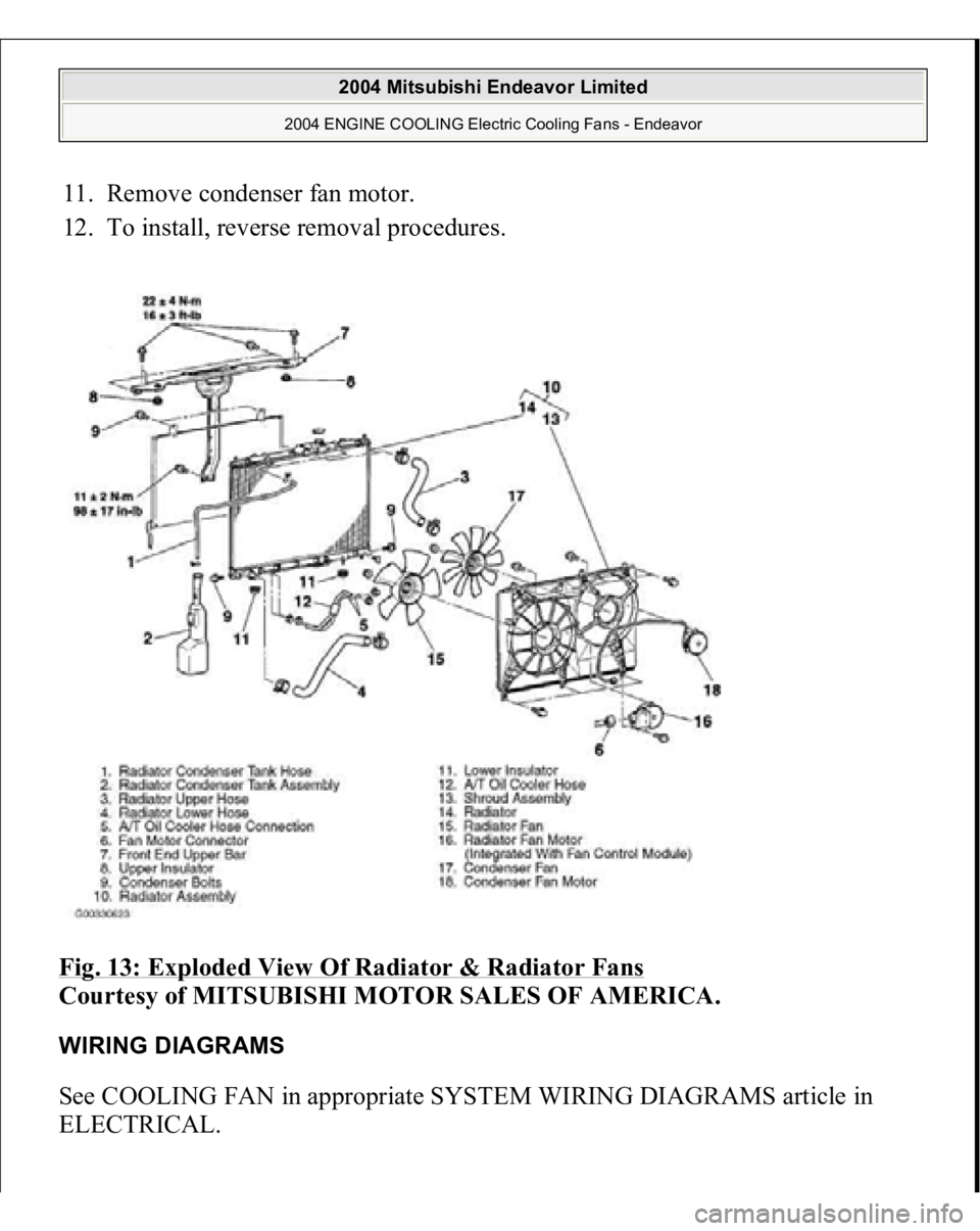
11. Remove condenser fan motor.
12. To install, reverse removal procedures.
Fig. 13: Exploded View Of Radiator & Radiator Fans
Courtesy of MITSUBISHI MOTOR SALES OF AMERICA.
WIRING DIAGRAMS See COOLING FAN in appropriate SYSTEM WIRING DIAGRAMS article in
ELECTRICAL.
2004 Mitsubishi Endeavor Limited
2004 ENGINE COOLING Electric Cooling Fans - Endeavor
Page 1300 of 3870
TORQUE SPECIFICATION
S
See illustration in REMOVAL & INSTALLATION
or OVERHAUL
.
WIRING DIAGRAMS For wiring diagrams, see STARTING/CHARGING
.
2004 Mitsubishi Endeavor Limited
2004 STARTING & CHARGING SYSTEMS Generators & Regulators - Endeavor
Page 2521 of 3870
means of a forged key or by connecting the ignition wiring directly. The system is
significantly safe and reliable against theft. In addition, the driver has only to turn
the ignition switch to the "ON" position to activate the immobilizer system. If the
requirements for starting the engine are not satisfied, the engine will be
immobilized. If a registered ignition key is lost, all your ignition keys need to be
registered again using scan tool MB991958 (MUT-III Sub Assembly) to ensure
security (Refer to ON
-VEHICLE SERVICE
). An additional ignition key can be
registered as follows (only if no ignition keys are lost):
Using scan tool MB991958 (MUT-III Sub Assembly) (Refer to ON
-
VEHICLE SERVICE
).
By operating two ignition keys that have been already registered (Refer toON
-
VEHICLE SERVICE
).
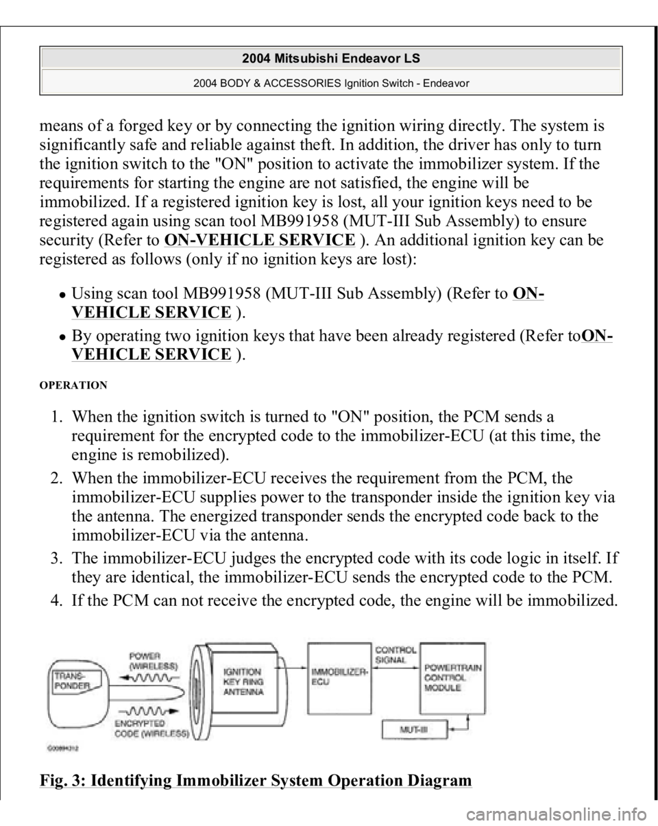
OPERATION 1. When the ignition switch is turned to "ON" position, the PCM sends a
requirement for the encrypted code to the immobilizer-ECU (at this time, the
engine is remobilized).
2. When the immobilizer-ECU receives the requirement from the PCM, the
immobilizer-ECU supplies power to the transponder inside the ignition key via
the antenna. The energized transponder sends the encrypted code back to the
immobilizer-ECU via the antenna.
3. The immobilizer-ECU judges the encrypted code with its code logic in itself. If
they are identical, the immobilizer-ECU sends the encrypted code to the PCM.
4. If the PCM can not receive the encrypted code, the engine will be immobilized.
Fig. 3: Identifying Immobilizer System Operation Diagram
2004 Mitsubishi Endeavor LS
2004 BODY & ACCESSORIES Ignition Switch - Endeavor