MITSUBISHI ENDEAVOR 2004 Service Repair Manual
ENDEAVOR 2004
MITSUBISHI
MITSUBISHI
https://www.carmanualsonline.info/img/19/57105/w960_57105-0.png
MITSUBISHI ENDEAVOR 2004 Service Repair Manual
Page 1350 of 3870
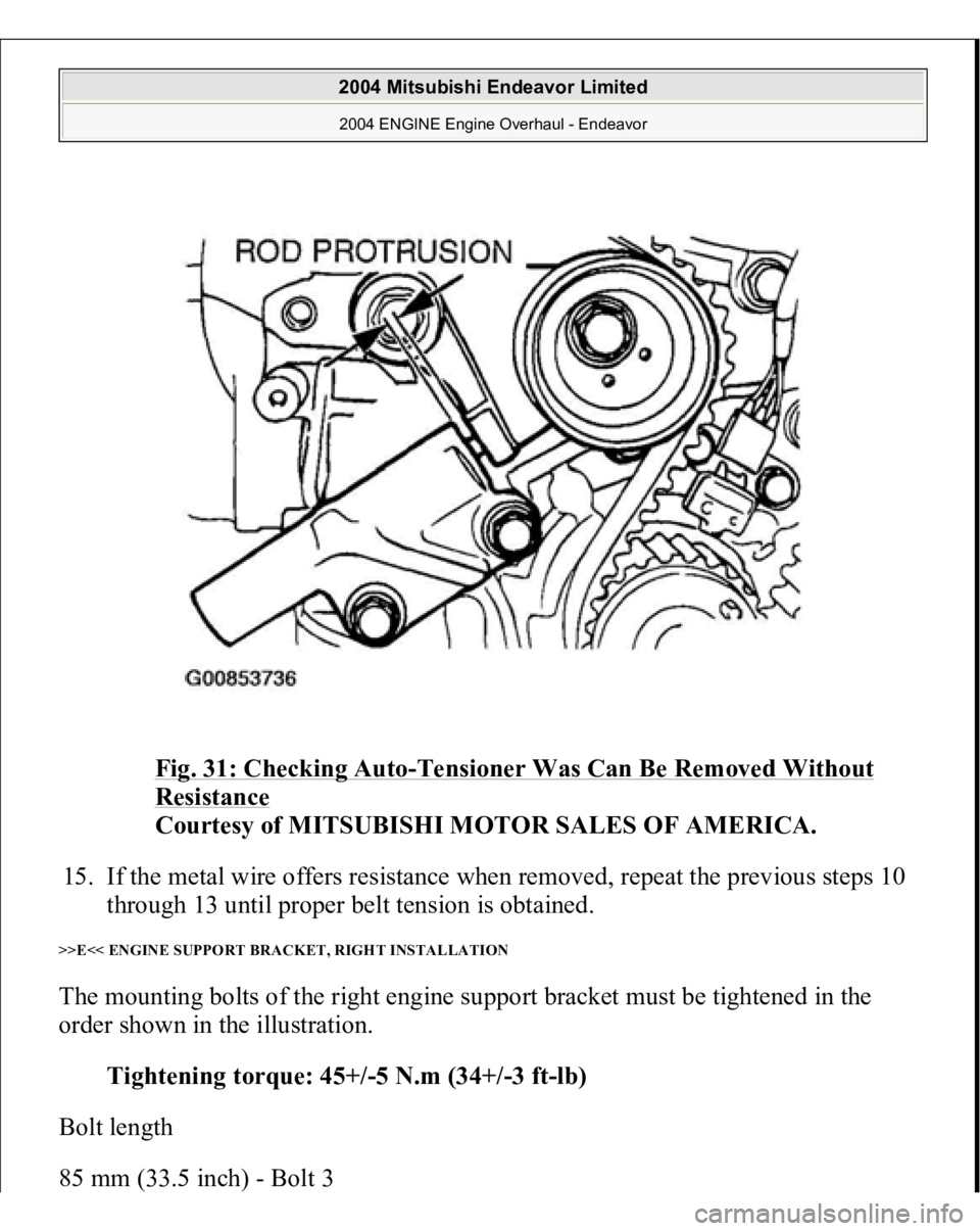
Fig. 31: Checking Auto
-Tensioner Was Can Be Removed Without
Resistance
Courtesy of MITSUBISHI MOTOR SALES OF AMERICA.
15. If the metal wire offers resistance when removed, repeat the previous steps 10
through 13 until proper belt tension is obtained.
>>E<< ENGINE SUPPORT BRACKET, RIGHT INSTALLATION The mounting bolts of the right engine support bracket must be tightened in the
order shown in the illustration.
Tightening torque: 45+/-5 N.m (34+/-3 ft-lb)
Bolt length
85 mm
(33.5 inch
) - Bolt
3
2004 Mitsubishi Endeavor Limited 2004 ENGINE Engine Overhaul - Endeavor
Page 1586 of 3870
Fig. 72: Tightening Bolts In Order
Courtesy of MITSUBISHI MOTOR SALES OF AMERICA.
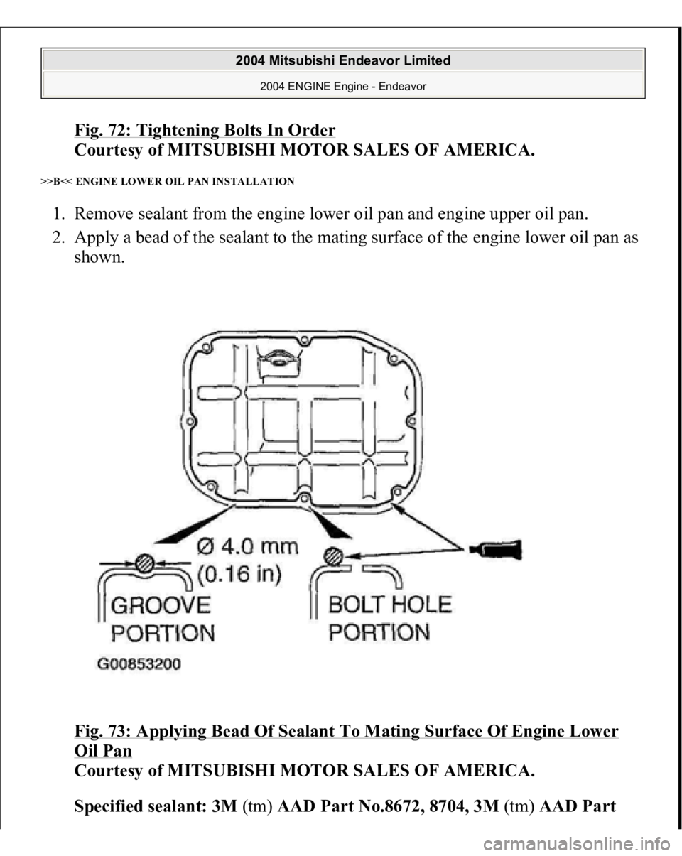
>>B<< ENGINE LOWER OIL PAN INSTALLATION 1. Remove sealant from the engine lower oil pan and engine upper oil pan.
2. Apply a bead of the sealant to the mating surface of the engine lower oil pan as
shown.
Fig. 73: Applying Bead Of Sealant To Mating Surface Of Engine Lower
Oil Pan
Courtesy of MITSUBISHI MOTOR SALES OF AMERICA.
Specified sealant: 3M(tm) AAD Part No.8672, 8704, 3M(tm) AAD Part
2004 Mitsubishi Endeavor Limited
2004 ENGINE Engine - Endeavor
Page 1588 of 3870
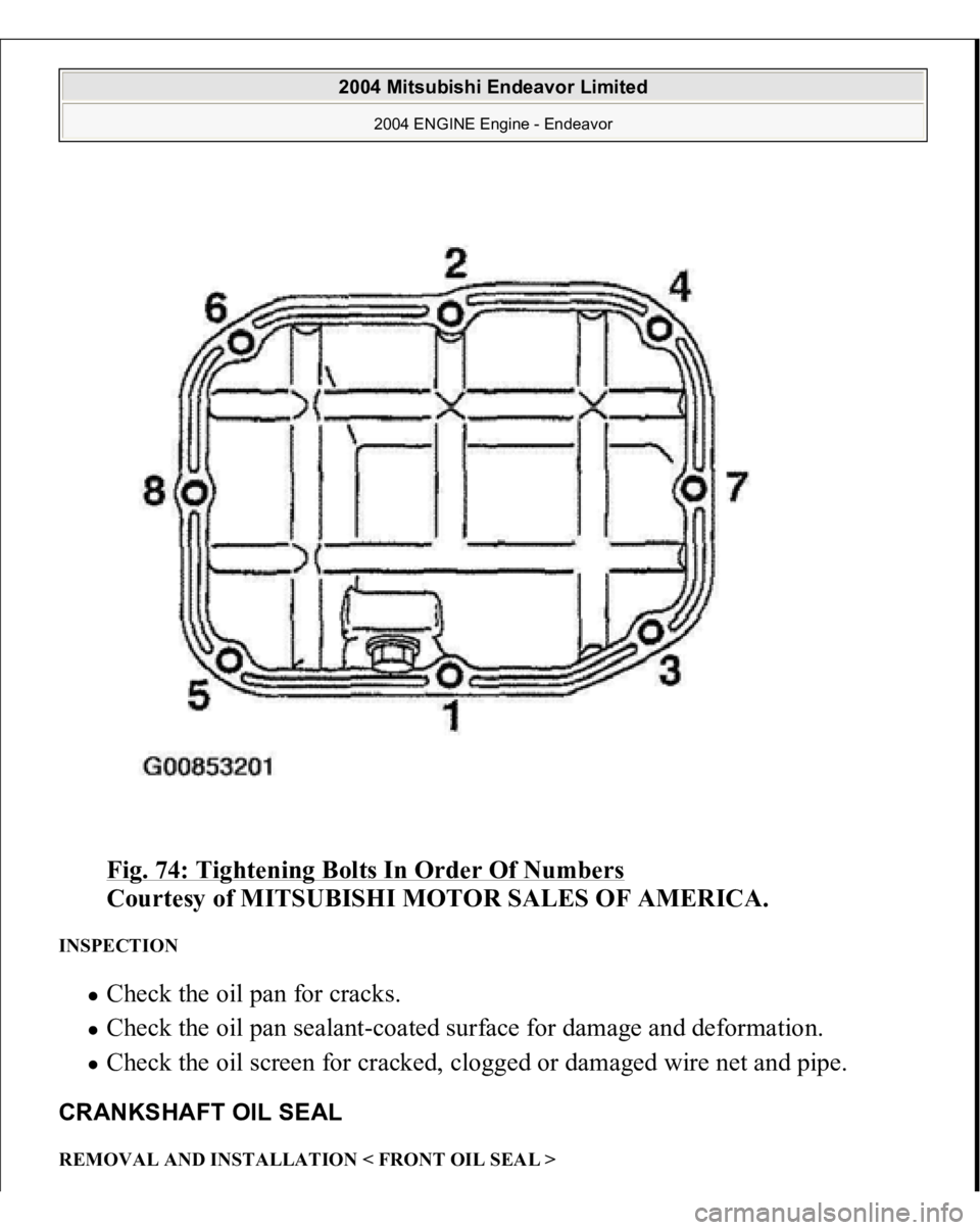
Fig. 74: Tightening Bolts In Order Of Numbers
Courtesy of MITSUBISHI MOTOR SALES OF AMERICA.
INSPECTION
Check the oil pan for cracks. Check the oil pan sealant-coated surface for damage and deformation. Check the oil screen for cracked, clogged or damaged wire net and pipe.
CRANKSHAFT OIL SEAL REMOVAL AND INSTALLATION < FRONT OIL SEAL >
2004 Mitsubishi Endeavor Limited
2004 ENGINE Engine - Endeavor
Page 1600 of 3870
1. Use a scraper to clean the gasket surface of the cylinder head assembly.
2. Using special tool MD998051 and a torque wrench, tighten the bolts to the
specified torque in the order shown in the illustration. (in two or three cycles)
Tightening torque: 108 +/- 5 N.m (80 +/- 3 ft-lb) +/- 0 N.m (0 in-lb) +/-
108 +/- 5 N.m (80 +/- 3 ft-lb)
damage may result.
CAUTION: Install the head bolt washers with the beveled
side facing upwards as shown in the illustration.
2004 Mitsubishi Endeavor Limited
2004 ENGINE Engine - Endeavor
Page 2875 of 3870
Courtesy of MITSUBISHI MOTOR SALES OF AMERICA
.
INSTALLATION SERVICE POINT >>A<< STEERING COLUMN SHAFT ASSEMBLY INSTALLATION Ensure that the tilt lever is in the lock position, and install the steering column.
Tighten the four bolts finger-tight in the order shown in illustration, and then
tighten them to the specified torque in the order shown in illustration.
Tightening torque: 12 +/- 2 N.m (102 +/- 22 in-lb)
CAUTION:
1. If reusin
g the steerin
g column, do not release the
tilt lever until the steering column shaft has been
installed.
2. If a new steering column is being installed, do
not release the tilt lever until it has been
installed. Do not remove the tilt lever fixing band
until the installation is completed.
3. When installing the steering column, do not leave
it fixed temporarily at only one point and make
sure the column shaft is not shaken strongly. If
this happens, the collision absorbing mechanism
at the column shaft mounting location may be
damaged.
2004 Mitsubishi Endeavor LS
2004 STEERING Power Steering - Endeavor
Page 2891 of 3870
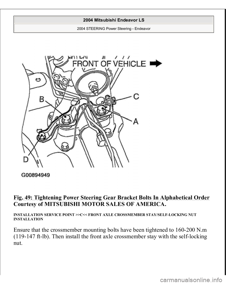
Fig. 49: Tightening Power Steering Gear Bracket Bolts In Alphabetical Order
Courtesy of MITSUBISHI MOTOR SALES OF AMERICA.
INSTALLATION SERVICE POINT >>C<< FRONT AXLE CROSSMEMBER STAY/SELF-LOCKING NUT
INSTALLATION Ensure that the crossmember mounting bolts have been tightened to 160-200 N.m
(119-147 ft-lb). Then install the front axle crossmember stay with the self-locking
nut.
2004 Mitsubishi Endeavor LS
2004 STEERING Power Steering - Endeavor
