fuel MITSUBISHI ENDEAVOR 2004 Service Repair Manual
[x] Cancel search | Manufacturer: MITSUBISHI, Model Year: 2004, Model line: ENDEAVOR, Model: MITSUBISHI ENDEAVOR 2004Pages: 3870, PDF Size: 98.47 MB
Page 792 of 3870
2004 ENGINE COOLING
Electric Cooling Fans - Endeavor
DESCRIPTION & OPERATION The fan control module is powered from fusible link No. 2. See Fig. 1
. The PCM
judges the required revolution speed of radiator fan motor and condenser fan motor
using input signals transmitted from the A/C switch, automatic compressor
controller, vehicle speed sensor and engine coolant temperature sensor. The PCM
activates the fan control module to drive the radiator fan motor and condenser fan
motor. COMPONENT LOCATIONS COMPONENT LOCATIONS Component
Location
Condenser Fan
(1) Behind Radiator
Fan Control Module
(1) Integrated With Radiator Fan Motor
Fan Control Relay
In Engine Compartment Fuse/Relay
Box
Fusible Link No. 2
(2) In Engine Compartment Fuse/Relay
Box
Multi-Port Fuel Injection (MFI) Relay
In Engine Compartment Fuse/Relay
Box
Radiator Fan
(1) Behind Radiator
(1)
See Fig. 13
.
(2)
See Fig. 1
.
2004 Mitsubishi Endeavor Limited
2004 ENGINE COOLING Electric Cooling Fans - Endeavor
2004 Mitsubishi Endeavor Limited
2004 ENGINE COOLING Electric Cooling Fans - Endeavor
Page 797 of 3870
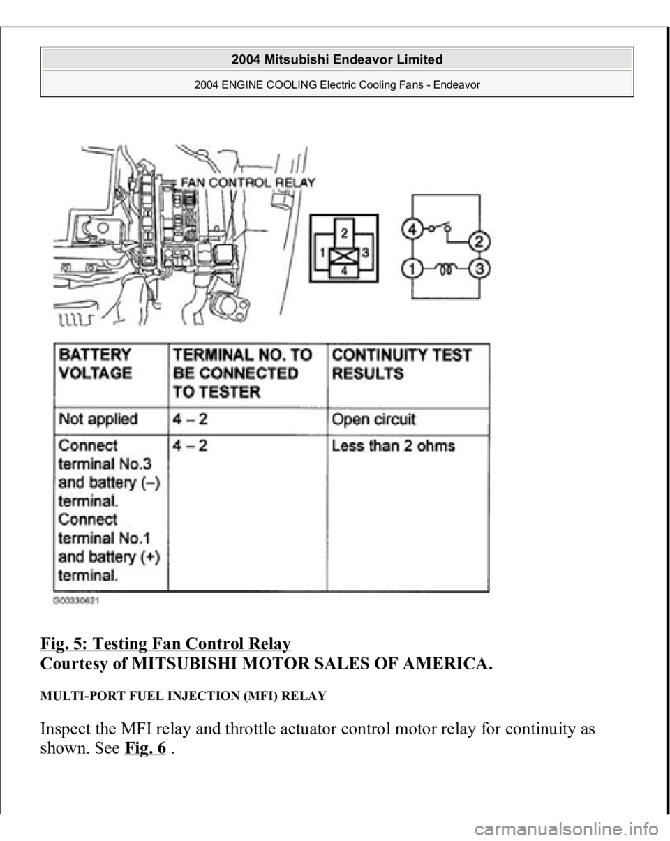
Fig. 5: Testing Fan Control Relay
Courtesy of MITSUBISHI MOTOR SALES OF AMERICA.
MULTI-PORT FUEL INJECTION (MFI) RELAY Inspect the MFI relay and throttle actuator control motor relay for continuity as
shown. See Fi
g. 6 .
2004 Mitsubishi Endeavor Limited
2004 ENGINE COOLING Electric Cooling Fans - Endeavor
Page 798 of 3870
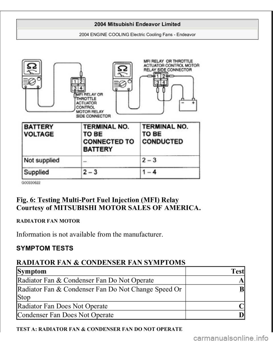
Fig. 6: Testing Multi
-Port Fuel Injection (MFI) Relay
Courtesy of MITSUBISHI MOTOR SALES OF AMERICA.
RADIATOR FAN MOTOR Information is not available from the manufacturer. SYMPTOM TESTS RADIATOR FAN & CONDENSER FAN SYMPTOMS TEST A: RADIATOR FAN & CONDENSER FAN DO NOT OPERATESymptom
Test
Radiator Fan & Condenser Fan Do Not Operate
A
Radiator Fan & Condenser Fan Do Not Change Speed Or
Stop
B
Radiator Fan Does Not Operate
C
Condenser Fan Does Not Operate
D
2004 Mitsubishi Endeavor Limited
2004 ENGINE COOLING Electric Cooling Fans - Endeavor
Page 799 of 3870
Technical Descriptio
n
The cause could be a malfunction of the fan control module power supply or
ground circuit. The cause could also be a malfunction of the fan control module or the PCM.
Troubleshooting Hints
Malfunction of fusible link. Malfunction of fan control relay. Malfunction of MFI relay. Malfunction of radiator fan motor. Malfunction of condenser fan motor. Malfunction of fan control module. Malfunction of PCM. Damaged wiring harness or connector.
Diagnosis 1. Disconnect fan control module connector A-23. See Fig. 7
. Measure for
voltage between terminal No. 3 (harness side of the connector) and ground
when ignition switch is turned to the ON position. If battery voltage is not
achieved, go to next step. If battery voltage is achieved, go to step 8 .
2. Check fan control relay. See FAN CONTROL RELAY under
COMPONENTS TESTS. If fan control relay is okay, go to next step. If fan
control relay is not okay, replace it and retest.
3. Check the MFI relay. See MULTI
-PORT FUEL INJECTION (MFI)
RELAY
under COMPONENT TESTS. If MFI relay is okay, go to next step. If
MFI relay is not okay, replace it and retest.
4. Check for harness damage in Black/Yellow wire between fusible link No. 2
and terminal No. 4 of fan control relay connector A-10X. See Fig. 8
. If wire is
okay, go to next step. If wire is damaged, repair or replace as necessary and
retest.
5. Check for harness damage in Blue wire between terminal No. 2 of fan control
rela
y connector
A-10X and terminal No. 3 of fan control module connector A-
2004 Mitsubishi Endeavor Limited
2004 ENGINE COOLING Electric Cooling Fans - Endeavor
Page 804 of 3870
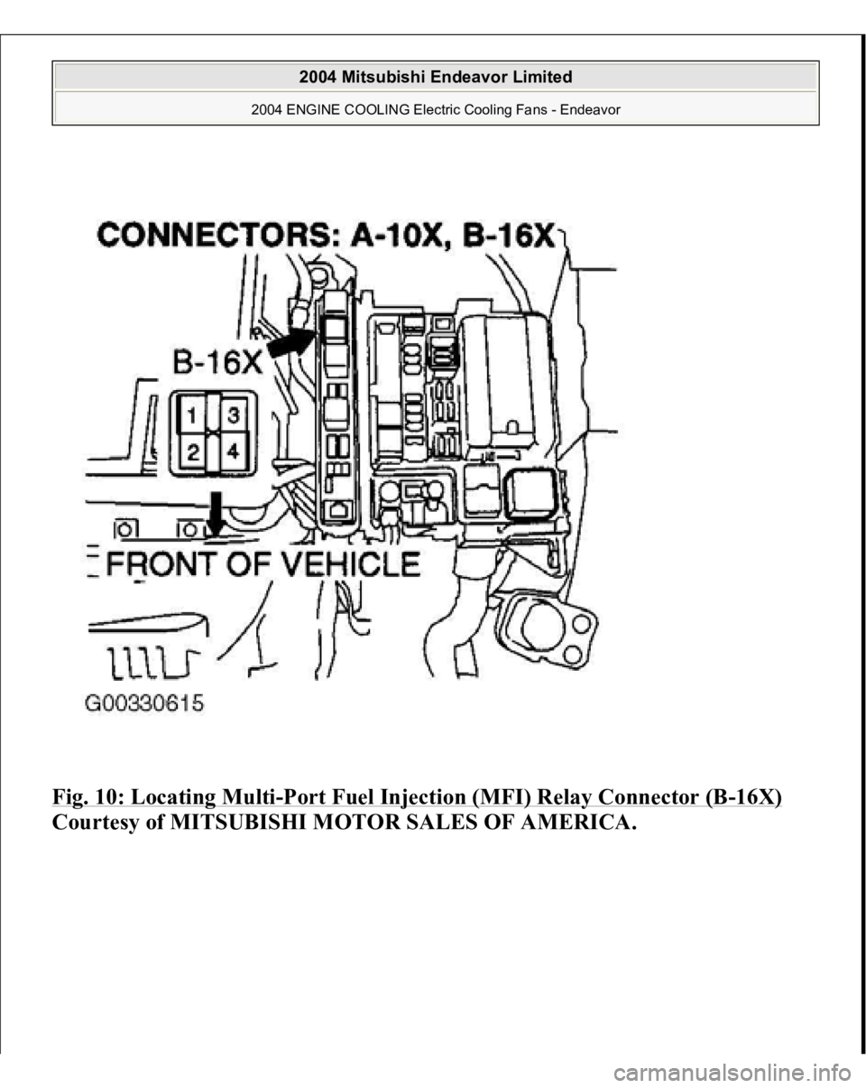
Fig. 10: Locating Multi
-Port Fuel Injection (MFI) Relay Connector (B
-16X)
Courtesy of MITSUBISHI MOTOR SALES OF AMERICA.
2004 Mitsubishi Endeavor Limited
2004 ENGINE COOLING Electric Cooling Fans - Endeavor
Page 1093 of 3870
2004 MITSUBISH
I
Endeavor
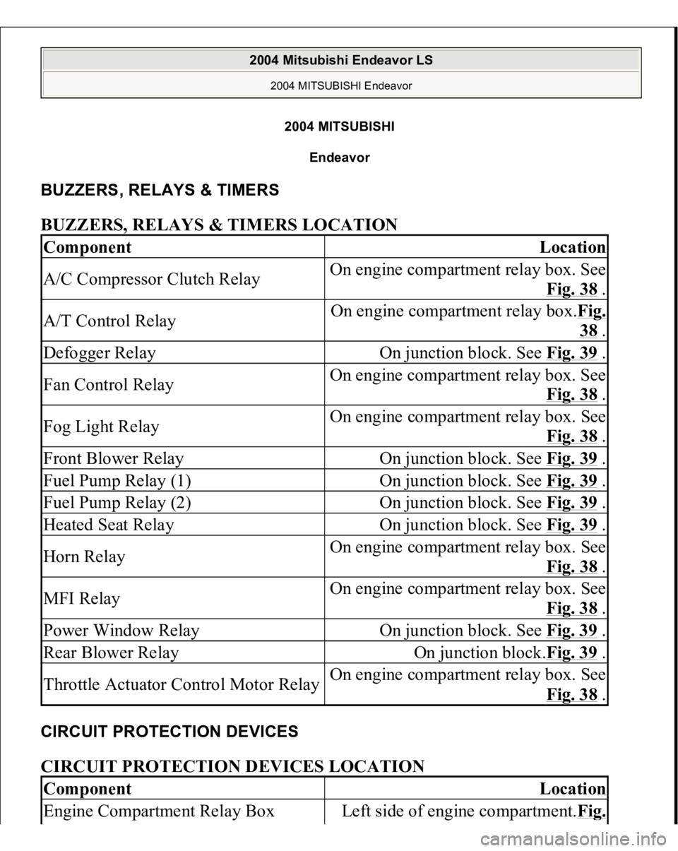
BUZZERS, RELAYS & TIMERS BUZZERS, RELAYS & TIMERS LOCATION CIRCUIT PROTECTION DEVICES CIRCUIT PROTECTION DEVICES LOCATION Component
Location
A/C Compressor Clutch Relay
On engine compartment relay box. See
Fig. 38
.
A/T Control Relay
On engine compartment relay box.Fig.
38 .
Defogger Relay
On junction block. See Fig. 39
.
Fan Control Relay
On engine compartment relay box. See
Fig. 38
.
Fog Light Relay
On engine compartment relay box. See
Fig. 38
.
Front Blower Relay
On junction block. See Fig. 39
.
Fuel Pump Relay (1)
On junction block. See Fig. 39
.
Fuel Pump Relay (2)
On junction block. See Fig. 39
.
Heated Seat Relay
On junction block. See Fig. 39
.
Horn Relay
On engine compartment relay box. See
Fig. 38
.
MFI Relay
On engine compartment relay box. See
Fig. 38
.
Power Window Relay
On junction block. See Fig. 39
.
Rear Blower Relay
On junction block.Fig. 39
.
Throttle Actuator Control Motor Relay
On engine compartment relay box. See
Fig. 38
.
Component
Location
Engine Compartment Relay Box
Left side of engine compartment.Fi
g.
2004 Mitsubishi Endeavor LS
2004 MITSUBISHI Endeavor
2004 Mitsubishi Endeavor LS
2004 MITSUBISHI Endeavor
Page 1095 of 3870

MOTORS MOTORS LOCATION SENDING UNITS & SENSORS SENDING UNITS & SENSORS LOCATION
4 .
Power Window Main Switch CPU
Integral to power window main switch.
See Fig. 15
.
SRS ECU
Under front of center console.Fig. 14
.
Sunroof ECU
At front of sunroof opening.Fig. 13
.
Component
Location
Door Lock Actuator (Left Front) (E-
20)
Rear of left front door.Fig. 77
.
Door Lock Actuator (Left Rear) (E-13)
Rear of left rear door.Fig. 77
.
Door Lock Actuator (Right Front) (E-
03)
Rear of right front door.Fig. 77
.
Door Lock Actuator (Right Rear) (E-
07)
Rear of right rear door.Fig. 77
.
Fuel Pump Module
In top of fuel tank.Fig. 64
.
Liftgate Actuator (F-11)
Lower center of liftgate. See Fig. 88
.
Power Steering Oil Pump
Lower right side of engine
compartment. See Fig. 36
.
Rear Blower Motor (C-20)
Rear of center console.Fig. 76
.
Rear Washer Motor (A-26)
In washer tank assembly.Fig. 79
.
Sunroof Motor Assembly
Right front of roof. See Fig. 62
.
Windshield Washer Motor (A-27)
In washer tank assembly.Fig. 79
.
Windshield Wiper Motor (A-03)
On left side of firewall.Fig. 79
.
Component
Location
ABS G Sensor Or G & Yaw Rate
Sensor
Under center console. See Fig. 67
.
Acceleration Pedal Position
Above accelerator pedal.Fig. 59
.
2004 Mitsubishi Endeavor LS
2004 MITSUBISHI Endeavor
Page 1096 of 3870
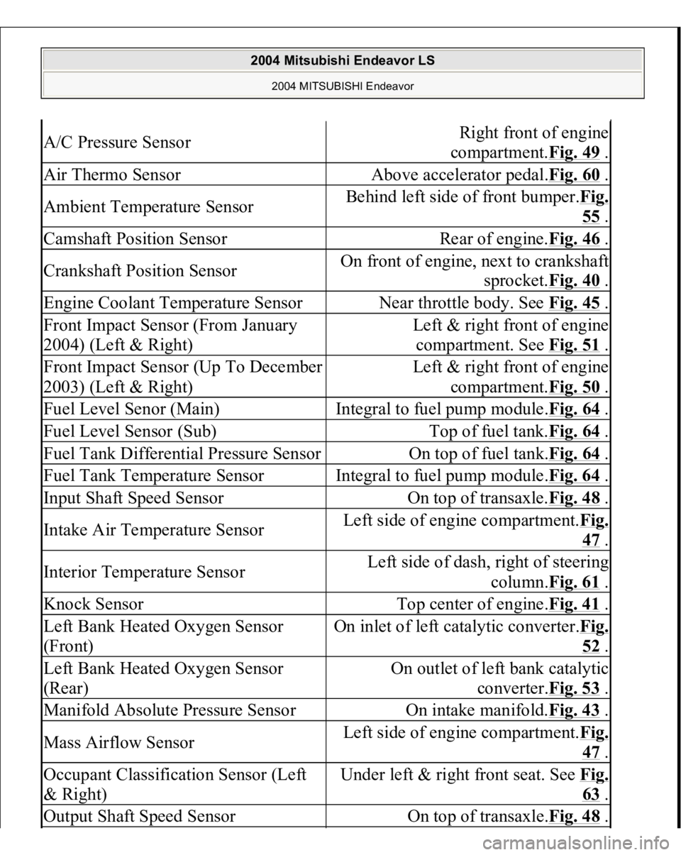
A/C Pressure Sensor
Right front of engine
compartment.Fig. 49
.
Air Thermo Sensor
Above accelerator pedal.Fig. 60
.
Ambient Temperature Sensor
Behind left side of front bumper.Fig.
55 .
Camshaft Position Sensor
Rear of engine.Fig. 46
.
Crankshaft Position Sensor
On front of engine, next to crankshaft
sprocket.Fig. 40
.
Engine Coolant Temperature Sensor
Near throttle body. See Fig. 45
.
Front Impact Sensor (From January
2004) (Left & Right)
Left & right front of engine
compartment. See Fig. 51
.
Front Impact Sensor (Up To December
2003) (Left & Right)
Left & right front of engine
compartment.Fig. 50
.
Fuel Level Senor (Main)
Integral to fuel pump module.Fig. 64
.
Fuel Level Sensor (Sub)
Top of fuel tank.Fig. 64
.
Fuel Tank Differential Pressure Sensor
On top of fuel tank.Fig. 64
.
Fuel Tank Temperature Sensor
Integral to fuel pump module.Fig. 64
.
Input Shaft Speed Sensor
On top of transaxle.Fig. 48
.
Intake Air Temperature Sensor
Left side of engine compartment.Fi
g.
47 .
Interior Temperature Sensor
Left side of dash, right of steering
column.Fig. 61
.
Knock Sensor
Top center of engine.Fig. 41
.
Left Bank Heated Oxygen Sensor
(Front)
On inlet of left catalytic converter.Fi
g.
52 .
Left Bank Heated Oxygen Sensor
(Rear)
On outlet of left bank catalytic
converter.Fig. 53
.
Manifold Absolute Pressure Sensor
On intake manifold.Fig. 43
.
Mass Airflow Sensor
Left side of engine compartment.Fi
g.
47 .
Occupant Classification Sensor (Left
& Right)
Under left & right front seat. See Fi
g.
63 .
Output Shaft Speed Sensor
On top of transaxle.Fig. 48
.
2004 Mitsubishi Endeavor LS
2004 MITSUBISHI Endeavor
Page 1097 of 3870
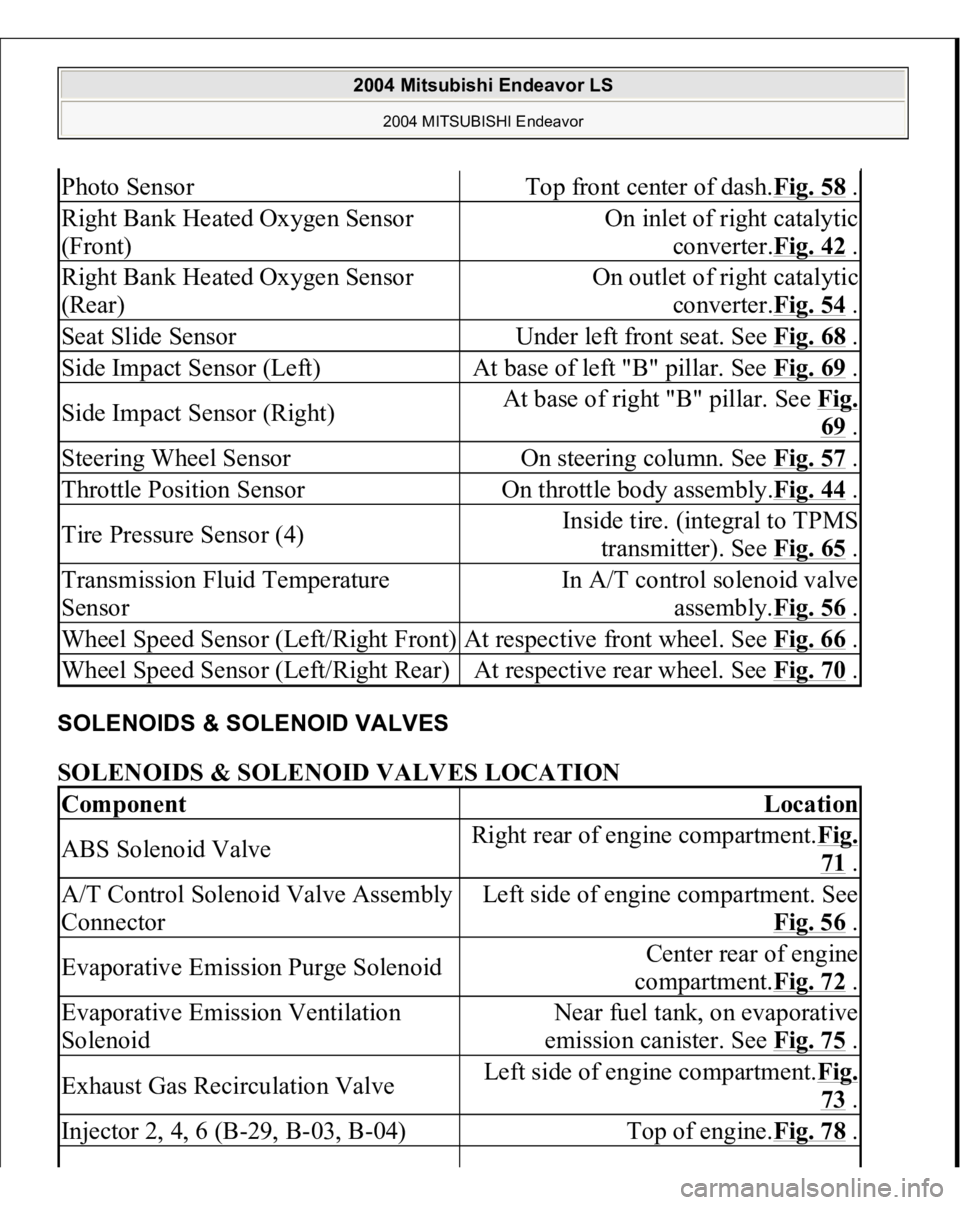
SOLENOIDS & SOLENOID VALVES SOLENOIDS & SOLENOID VALVES LOCATION Photo Sensor
Top front center of dash.Fig. 58
.
Right Bank Heated Oxygen Sensor
(Front)
On inlet of right catalytic
converter.Fig. 42
.
Right Bank Heated Oxygen Sensor
(Rear)
On outlet of right catalytic
converter.Fig. 54
.
Seat Slide Sensor
Under left front seat. See Fig. 68
.
Side Impact Sensor (Left)
At base of left "B" pillar. See Fig. 69
.
Side Impact Sensor (Right)
At base of right "B" pillar. See Fig.
69 .
Steering Wheel Sensor
On steering column. See Fig. 57
.
Throttle Position Sensor
On throttle body assembly.Fig. 44
.
Tire Pressure Sensor (4)
Inside tire. (integral to TPMS
transmitter). See Fig. 65
.
Transmission Fluid Temperature
Sensor
In A/T control solenoid valve
assembly.Fig. 56
.
Wheel Speed Sensor (Left/Right Front)
At respective front wheel. See Fig. 66
.
Wheel Speed Sensor (Left/Right Rear)
At respective rear wheel. See Fig. 70
.
Component
Location
ABS Solenoid Valve
Right rear of engine compartment.Fig.
71 .
A/T Control Solenoid Valve Assembly
Connector
Left side of engine compartment. See
Fig. 56
.
Evaporative Emission Purge Solenoid
Center rear of engine
compartment.Fig. 72
.
Evaporative Emission Ventilation
Solenoid
Near fuel tank, on evaporative
emission canister. See Fig. 75
.
Exhaust Gas Recirculation Valve
Left side of engine compartment.Fig.
73 .
Injector 2, 4, 6 (B-29, B-03, B-04)
Top of engine.Fig. 78
.
2004 Mitsubishi Endeavor LS
2004 MITSUBISHI Endeavor
Page 1202 of 3870
NO: Replace it, then go to Step 1 .
STEP 3. Check the MFI relay.
Refer to MULTIPORT FUEL INJECTION (MFI) RELAY AND
THROTTLE ACTUATOR CONTROL MOTOR RELAY CONTINUITY CHECK
.
Q: Is the MFI relay in good condition?
YES: Go to Step 4.
NO: Replace it, then go to Step 1 .
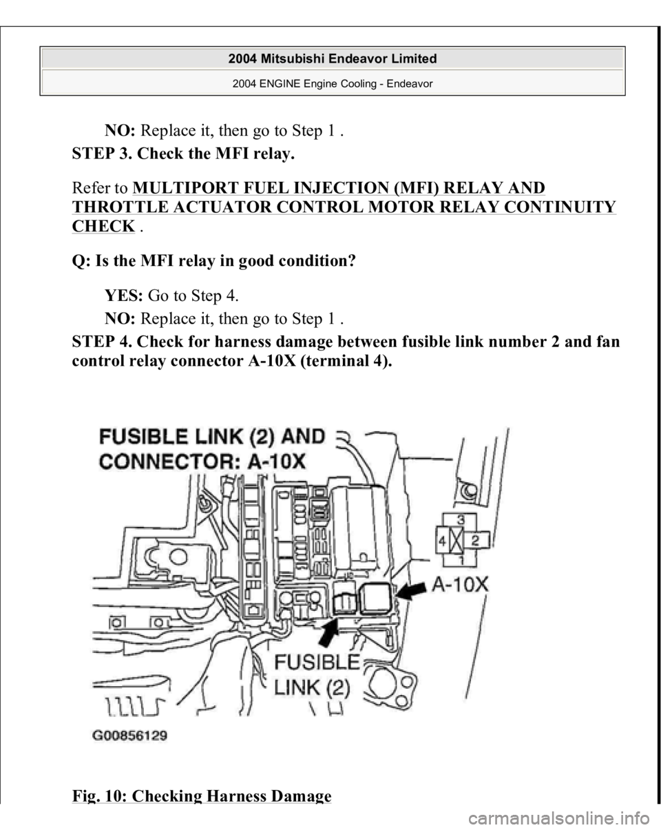
STEP 4. Check for harness dama
ge between fusible link number 2 and fan
control relay connector A-10X (terminal 4).
Fi
g. 10: Checkin
g Harness Dama
ge
2004 Mitsubishi Endeavor Limited 2004 ENGINE Engine Cooling - Endeavor