seat adjustment MITSUBISHI GALANT 1989 Service User Guide
[x] Cancel search | Manufacturer: MITSUBISHI, Model Year: 1989, Model line: GALANT, Model: MITSUBISHI GALANT 1989Pages: 1273, PDF Size: 37.62 MB
Page 956 of 1273
![MITSUBISHI GALANT 1989 Service User Guide ACTIVE-ELECTRONIC CONTROL SUSPENSION - Troubleshooting 33B-17
CHECKING ACCORDING TO CHARTS CLASSIFIED BY THE MALFUNCTION SYMPTOM
[A] DIAGNOSTIC TROUBLE CODE NO.54
No
Yes
b Excessive vehicle-height ad-](/img/19/57312/w960_57312-955.png "MITSUBISHI GALANT 1989 Service User Guide ACTIVE-ELECTRONIC CONTROL SUSPENSION - Troubleshooting 33B-17
CHECKING ACCORDING TO CHARTS CLASSIFIED BY THE MALFUNCTION SYMPTOM
[A] DIAGNOSTIC TROUBLE CODE NO.54
No
Yes
b Excessive vehicle-height ad-")
ACTIVE-ELECTRONIC CONTROL SUSPENSION - Troubleshooting 33B-17
CHECKING ACCORDING TO CHARTS CLASSIFIED BY THE MALFUNCTION SYMPTOM
[A] DIAGNOSTIC TROUBLE CODE NO.54
No
Yes
b Excessive vehicle-height ad-justment
(overload) overload). time (due to -Unload the vehicle and turn* the ignition key to OFF; then
restart the engine and check
whether or not the system
functions normally.
Is the installation position of Nothe height sensor correct?
Yes Improper setting of the heightc sensor, or malfunction of the
height sensor. l Correct the installationcposition of the height sen-
sor, or adjust the vehicle
-height sensor rod.
l Check the height sensor. Refer to troubleshooting
hints [IO] and
[ll]classified by circuit.
Are the front strut and rear
NoMalfunction of the rolling
shock absorber unit air spr-* diaphragm.
Repair the rolling diaphragm,
or replace the shock absorber
ings in normal condition?Lunit.
(become folded)
Yes
Is the sound of operation
NoThe solenoid valves remain
heard from each solenoid closed, or there is air leakage
valve necessary for th
e
’ due to a malfunction of the
vehicle-height adjustment? valve seat.
Yes
Is the air pressure in the
vehicle-height adjustment
Nopressure line 950 kPa (135
psi) or higher?
I
Yes Damaged or disconnected
wiring of the high-pressure
switch, or incorrect vehicle
-height adjustment pressureline.
l Check the high-pressure switch circuit.
* Refer to troubleshooting hint [5] classified by circuit.
l Correct the clogging pro-
blem, or replace the air
tube.
Control unit malfunction.
[B] DIAGNOSTIC TROUBLE CODE NO.55
- No
Does the compressor func-
tion normally?
Yes Replace the control unit.c l Power is not supplied to
the compressor.Refer to troubleshooting
hint
[18] classified by cir-
cuit.
0 Improper compressor com- pression.
Is the air pressure in the
Novehicle-height adjustment
pressure line 760 kPa (108psi) or lower? High-pressure
switch
isRefer to troubleshooting hint
shorted____* [5] classified by circuit.
Yes Air leakage.
TSB RevisionI
Page 1000 of 1273
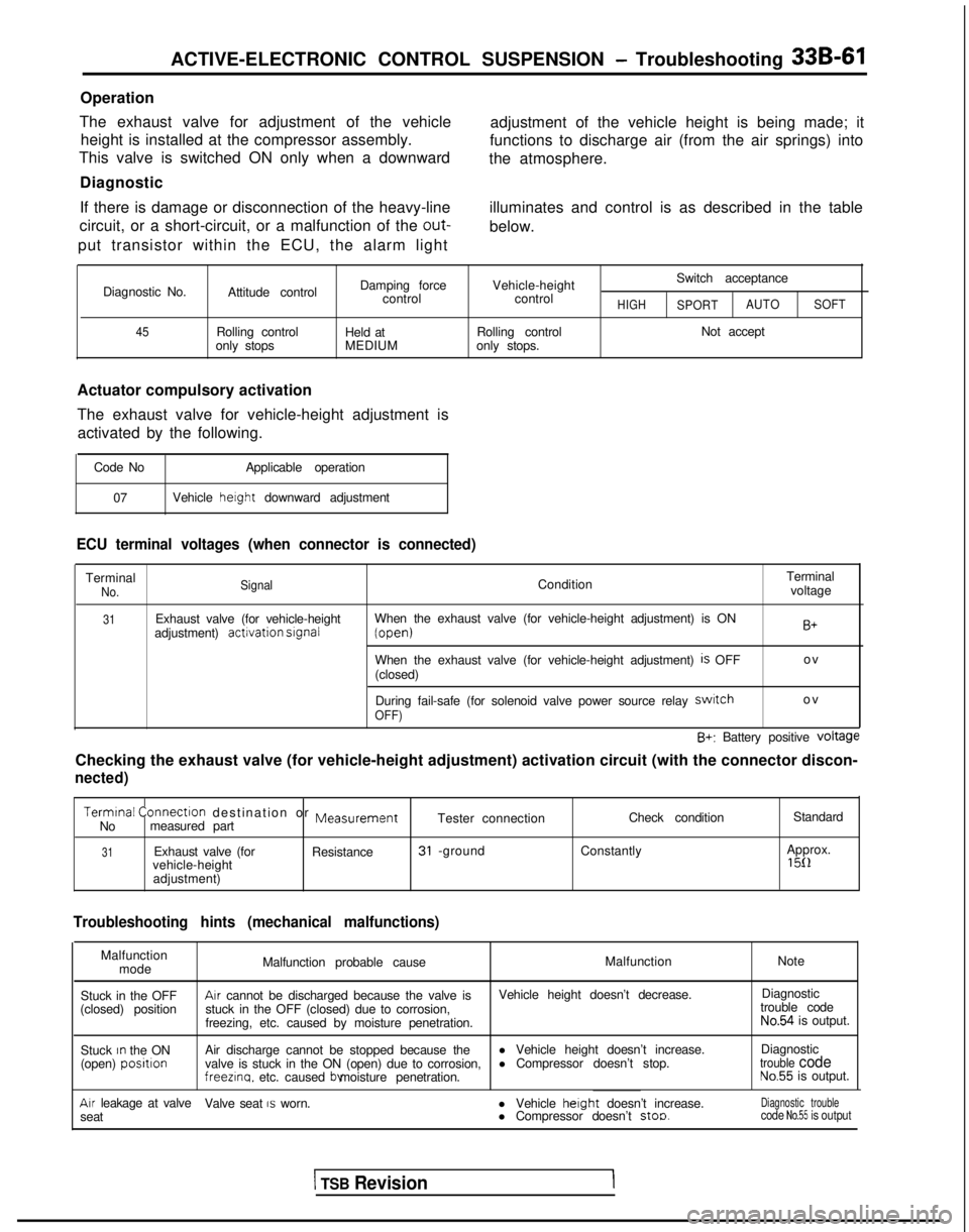
ACTIVE-ELECTRONIC CONTROL SUSPENSION - Troubleshooting 33B-61
Operation
The exhaust valve for adjustment of the vehicle height is installed at the compressor assembly.
This valve is switched ON only when a downward
Diagnostic
If there is damage or disconnection of the heavy-line
circuit, or a short-circuit, or a malfunction of the out-
put transistor within the ECU, the alarm light adjustment of the vehicle height is being made; it
functions to discharge air (from the air springs) into
the atmosphere.
illuminates and control is as described in the table
below.
Diagnostic No.
45
Attitude control
Rolling control
only stops Damping force
control
Held at
MEDIUM Vehicle-height
control
Rolling control
only stops. Switch acceptanceHIGHSPORT
AUTO
SOFT
Not accept
Actuator compulsory activation
The exhaust valve for vehicle-height adjustment is activated by the following.
Code No Applicable operation
07 Vehicle height
downward adjustment
ECU terminal voltages (when connector is connected)
TerminalNo. SignalCondition Terminal
voltage
31Exhaust valve (for vehicle-height
adjustment) activation srgnalWhen the exhaust valve (for vehicle-height adjustment) is ON (open)
When the exhaust valve (for vehicle-height adjustment)
is OFF
(closed)
B+
o
v
During fail-safe (for solenoid valve power source relay
swatcho
v
OFF)
B+: Battery positive voltage
Checking the exhaust valve (for vehicle-height adjustment) activation \
circuit (with the connector discon-
nected)
Termtnal
Connectlon destination or MeasurementCheck condition Standard
No measured part Tester connection
31Exhaust valve (for
Resistance31 -groundConstantly Approx.
vehicle-height1511adjustment)
Troubleshooting hints (mechanical malfunctions)
Malfunction mode Malfunction probable cause
Malfunction
Note
Stuck in the OFF
Arr cannot be discharged because the valve is Vehicle height doesn’t decrease.Diagnostic
(closed) position stuck in the OFF (closed) due to corrosion, trouble code
freezing, etc. caused by moisture penetration.
No.54 is output.
Stuck
rn the ON
(open) positlonAir discharge cannot be stopped because the l Vehicle height doesn’t increase.Diagnostic
valve is stuck in the ON (open) due to corrosion, l Compressor doesn’t stop.trouble codefreezlna.
etc. caused bv moisture penetration.No.55 is output.
Arr leakage at valve
Valve seat IS worn.
seat l Vehicle herght
doesn’t increase.
l Compressor doesn’t stoo.Diagnostic troublecode No.55 is output
1 TSB Revision
Page 1006 of 1273
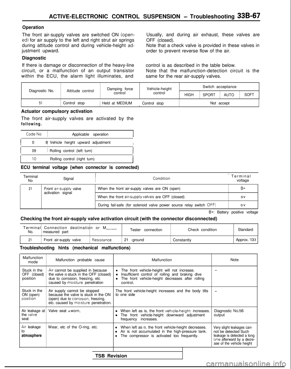
ACTIVE-ELECTRONIC CONTROL SUSPENSION - Troubleshooting 33B-67
Operation
The front air-supply valves are switched ON (open-
ed) for air supply to the left and right strut air springs
during attitude control and during vehicle-height
ad-
justment upward.
Diagnostic
If there is damage or disconnection of the heavy-line
circuit, or a malfunction of an output transistor
within the ECU, the alarm light illuminates, and Usually, and during air exhaust, these valves are
OFF (closed).
Note that a check valve is provided in these valves in
order to prevent reverse flow of the air.
control is as described in the table below. Note that the malfunction-detection circuit is the
same for the rear air-supply valves.
Diagnostic No. Attitude control Damping force
control Vehicle-height
control
HIGH
Switch acceptance
SPORT AUTOSOFT
51Control stop1 Held at MEDIUM
Control stop Not acceptI
Actuator compulsory activation
The front air-supply valves are activated by the
following
.
CodeNo
~
Applicable operation
I0
8 1
Vehicle herght upward adjustment
I
I09i Rolling control (left turn)I
L10Rolling control (right turn)I
ECU terminal voltage {when connector is connected)
TerminalNoSignal Conditron’ Termina
l
voltage
21Front atr-supply
valve
activation signal When the front air-supply valves are ON (open)B+
When the front arr-supply valves
are OFF (closed) ov
During fail-safe (for solenoid valve power source relay switch
OFF]o
v
B+: Battery positive voltage
Checking the front air-supply valve activation circuit (with the connec\
tor disconnected)
Terminal Connection destination or M easurement
No.measured part Tester connection
Check conditionStandard
21Front air-supply valve Resrstance
21 -ground
Constantly Approx. 1011
Troubleshooting hints (mechanical malfunctions)
Malfunction
mode Malfunction probable cause
MalfunctionNote
l Insufficient control of rolling and braking dive
position due to corrosion, freezing, etc lThe front vehicle-height decreases after rolling
caused by morsture
penetration
control.
Stuck in the Air supply cannot be stopped
ON (open) The front vehicle-height increases and the body tilts
-because the valve is stuck in the ON
to one sideposrtion
(open) due to corrosron.
freezing,
etc. caused by morsture
penetratron.
Air leakage at Valve seat IS worn,
l When left as is, the front
vehrcle-height increases.Diagnostic No.56
the valvel The front vehicle-height downward adjustment output
seat frequency increases.
Arr leakageW
ear, etc of the O-ring, etc.
lWhen left as IS. the front vehicle-height decreases.Very slight leakages can-to
l not be detected Such
atmosphere Air is not accumulated in the high-pressure tank.lThe compressor is activated too frequently.leakage is detected a longtime
afterward by a decre-
ase of the vehicle height
TSB Revision
Page 1008 of 1273
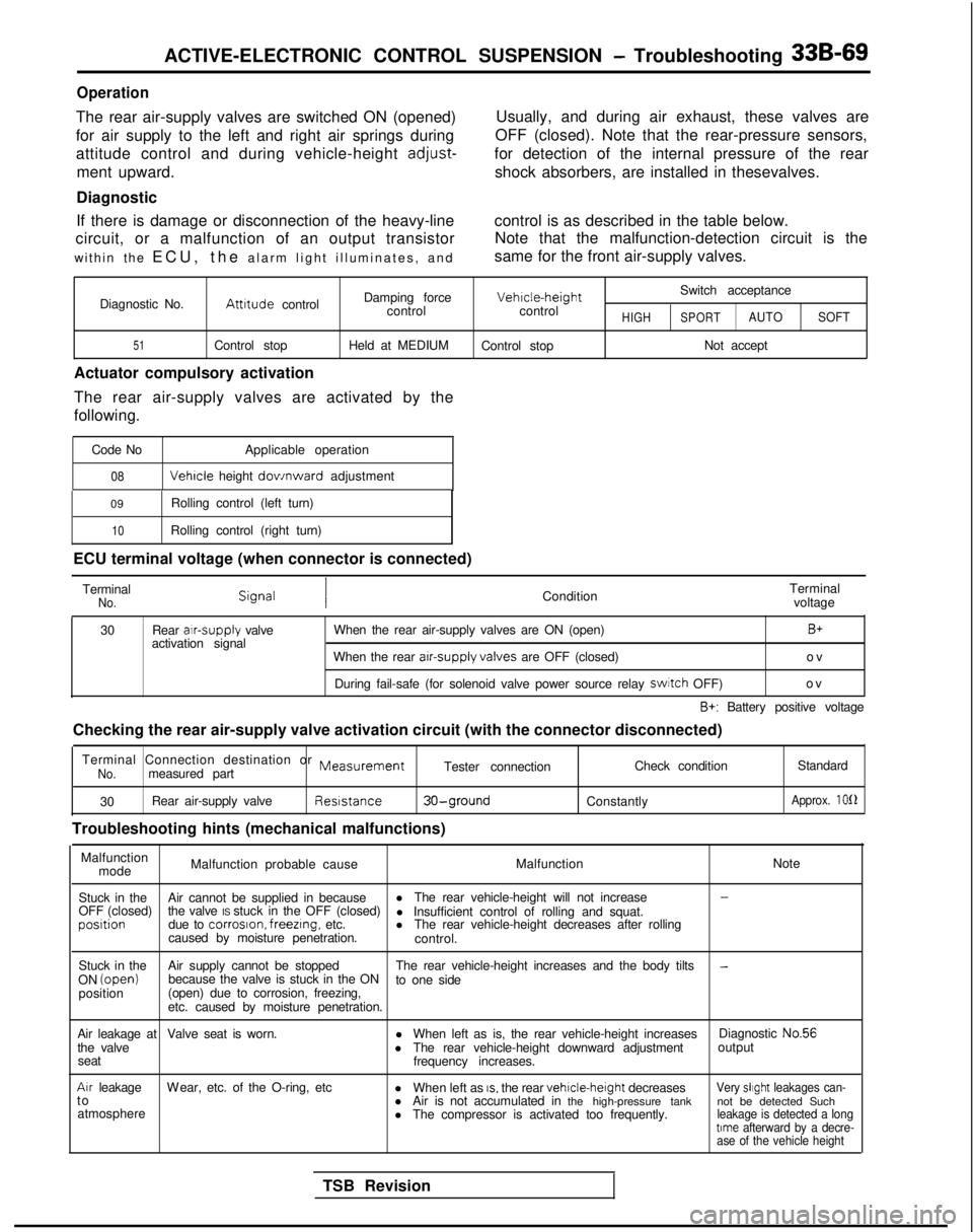
ACTIVE-ELECTRONIC CONTROL SUSPENSION - Troubleshooting 33B-69
Operation
The rear air-supply valves are switched ON (opened)
for air supply to the left and right air springs during
attitude control and during vehicle-height
adjust-
ment upward.
Diagnostic Usually, and during air exhaust, these valves are
OFF (closed). Note that the rear-pressure sensors,
for detection of the internal pressure of the rear shock absorbers, are installed in thesevalves.
If there is damage or disconnection of the heavy-line control is as described in the table below.
circuit, or a malfunction of an output transistor Note that the malfunction-detection circuit is the
within the ECU, the alarm light illuminates, and same for the front air-supply valves.
Switch acceptance
Diagnostic No.
Attrtude control Damping force Vehrcle-height
control controlHIGHSPORTAUTO SOFT
51Control stop Held at MEDIUM
Control stop Not accept
Actuator compulsory activation
The rear air-supply valves are activated by the
following.
Code No Applicable operation
08 Vehicle
height dov/nward adjustment
09 Rolling control (left turn)
10Rolling control (right turn)
ECU terminal voltage (when connector is connected)
Terminal
No.Condition Terminal
voltage
30 Rear alr-supply
valve
activation signal When the rear air-supply valves are ON (open)
B+
When the rear arr-supply valves
are OFF (closed) ov
During fail-safe (for solenoid valve power source relay switch
OFF) ov
B+: Battery positive voltage
Checking the rear air-supply valve activation circuit (with the connect\
or disconnected)
Terminal Connection destination or
MeasurementNo.measured part Tester connection
Check condition
Standard
30 Rear air-supply valve Reststance
30-ground
Troubleshooting hints (mechanical malfunctions)
Constantly
Approx. 1012
Malfunction
mode Malfunction probable cause
MalfunctionNote
Stuck in the Air cannot be supplied in because l
The rear vehicle-height will not increase
-
OFF (closed) the valve IS stuck in the OFF (closed)
l Insufficient control of rolling and squat.posrtion
due to corroson. freezrng,
etc. lThe rear vehicle-height decreases after rolling
caused by moisture penetration. control.
Stuck in the Air supply cannot be stopped The rear vehicle-height increases and the body tilts
-ON (open)
because the valve is stuck in the ON
to one side
position (open) due to corrosion, freezing,
etc. caused by moisture penetration.
Air leakage at Valve seat is worn. lWhen left as is, the rear vehicle-height increases Diagnostic No.56
the valve lThe rear vehicle-height downward adjustment output
seat frequency increases.
Arr leakageW
ear, etc. of the O-ring, etc
lWhen left as
IS, the rear vehrcle-height
decreasesVery slrght leakages can-t
o
lAir is not accumulated in the high-pressure tank not be detected Such
atmosphere lThe compressor is activated too frequently.
leakage is detected a longtrme afterward by a decre-
ase of the vehicle height
TSB Revision
Page 1010 of 1273
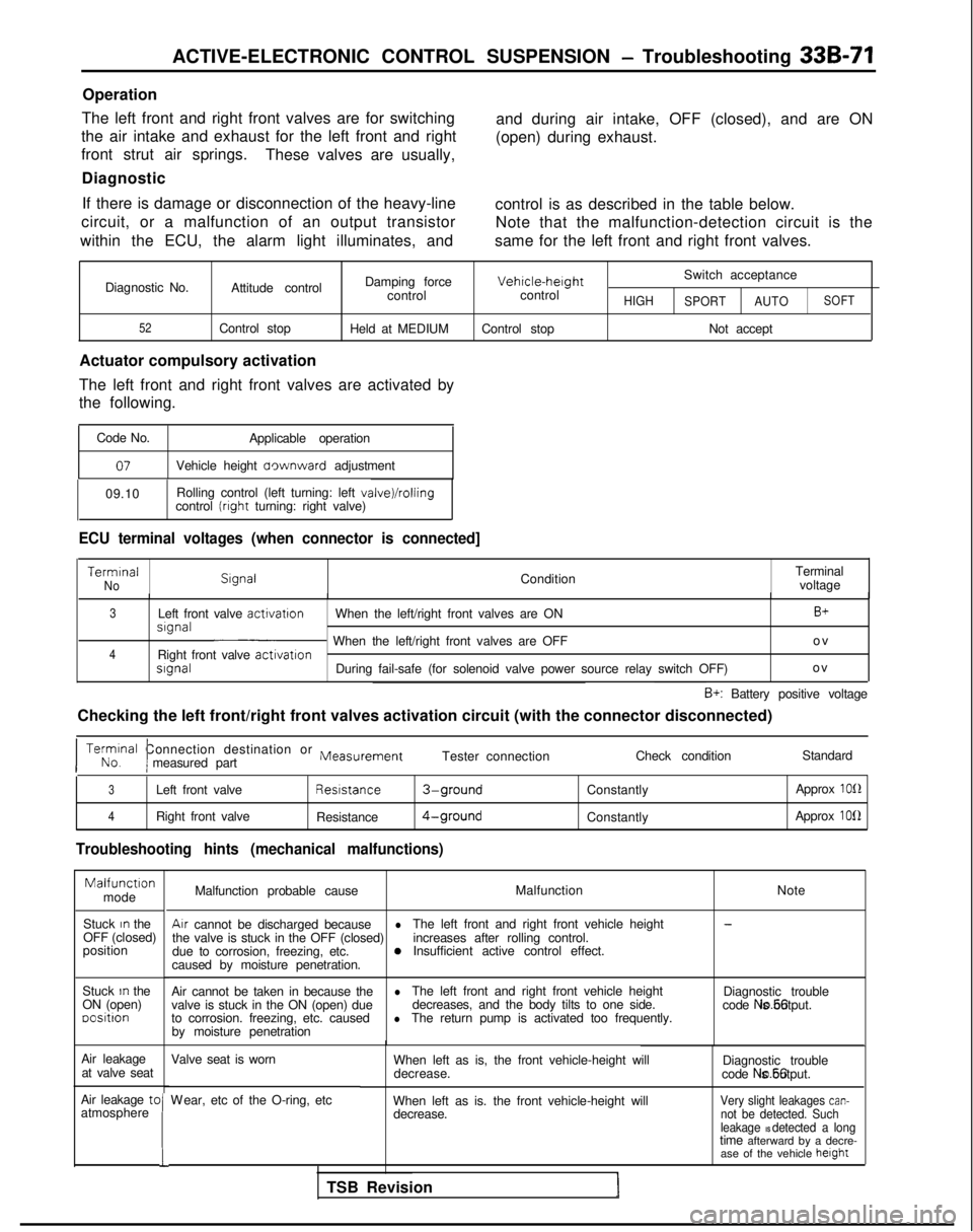
ACTIVE-ELECTRONIC CONTROL SUSPENSION - Troubleshooting 33B-71
Operation
The left front and right front valves are for switching
the air intake and exhaust for the left front and right
front strut air springs. These valves are usually,
Diagnostic and during air intake, OFF (closed), and are ON
(open) during exhaust.
If there is damage or disconnection of the heavy-line control is as described in the table below.
circuit, or a malfunction of an output transistor Note that the malfunction-detection circuit is the
within the ECU, the alarm light illuminates, and same for the left front and right front valves.
Diagnostic No.
52
Damping forceVehicle-herghtSwitch acceptance
Attitude control controlcontrol
HIGH
SPORT AUTOSOFT
Control stop
Held at MEDIUM Control stop Not accept
Actuator compulsory activation
The left front and right front valves are activated by
the following.
Code No. Applicable operation
07Vehicle height aownward adjustment
09.10 Rolling control (left turning: left
valve)/rollingcontrol (rrght turning: right valve)
ECU terminal voltages (when connector is connected] Termrnal
No
Slgnal
ConditionTerminal
voltage
3Left front valve activatron
When the left/right front valves are ONB+srgnal~ When the left/right front valves are OFF o
v
4Right front valve
activatronsrgnalDuring fail-safe (for solenoid valve power source relay switch OFF)
o
v
B+: Battery positive voltage
Checking the left front/right front valves activation circuit (with the\
connector disconnected)
I No. Terminal
Connection destination or
Measurement
Imeasured part Tester connection
Check conditionStandard
3Left front valve Resrstance3-groundConstantly
Approx 1012
4Right front valve
Resistance4-groundConstantly Approx 1012
Troubleshooting hints (mechanical malfunctions)Malfunctron
mode
Stuck
In the
OFF (closed)
position
Stuck
In the
ON (open) oositron
Air leakage at valve seat
Air leakage tc
atmosphere
!
Malfunction probable cause Malfunction
NoteAir
cannot be discharged because
l-
the valve is stuck in the OFF (closed) The left front and right front vehicle height
due to corrosion, freezing, etc. increases after rolling control.0Insufficient active control effect.
caused by moisture penetration.
Air cannot be taken in because the
lvalve is stuck in the ON (open) due The left front and right front vehicle height
Diagnostic trouble
decreases, and the body tilts to one side.
to corrosion. freezing, etc. caused code No.56 is output.lThe return pump is activated too frequently.
by moisture penetration
Valve seat is worn
W
ear, etc of the O-ring, etc
When left as is, the front vehicle-height will
decrease. Diagnostic trouble
code No.56 is output.
When left as is. the front vehicle-height will decrease.
Very slight leakages can-not be detected. Such
leakage IS detected a longtime afterward by a decre- ase of the vehicle height
TSB Revision
Page 1012 of 1273
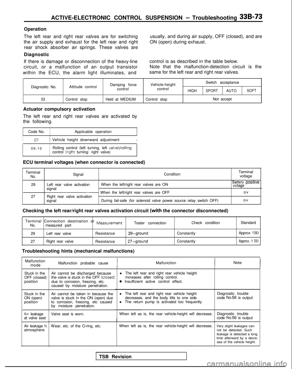
ACTIVE-ELECTRONIC CONTROL SUSPENSION - Troubleshooting 33B-73
Operation
The left rear and right rear valves are for switching
the air supply and exhaust for the left rear and right rear shock absorber air springs. These valves are
Diagnostic usually, and during air supply, OFF (closed), and are
ON (open) during exhaust.
If there is damage or disconnection of the heavy-line
circuit, or a malfunction of an output transistor
within the ECU, the alarm light illuminates, and control is as described in the table below.
Note that the malfunction-detection circuit is the
same for the left rear and right rear valves.
Diagnostic No.
53
Damping force Vehicle-height Switch acceptance
Attitude control controlcontrol
HIGHSPORTAUTOSOFT
Control stop
Held at MEDIUMControl stop Not accept
Actuator compulsory activation
The left rear and right rear valves are activated by
the following.
Code No. Applicable operation
I07/ Vehicle height downward adjustmentI
09.1
0
Rolling control (left turning, left
valve)/rollingcontrol (right
turning: right valve)
ECU terminal voltages (when connector is connected) Terminal
No.Signal ConditionTerminal
voltage
29 Left rear valve activation When the left/right rear valves are ON
signal
E3a3azg~ positive
~ When the left/right rear valves are OFF o
v
27 Right rear valve activation
signal During fail-safe (for solenoid valve power source relay switch OFF) ov
Checking the left rear/right rear valves activation circuit (with
the connector disconnected)
Terminal Connection destination or
MeasurementNo.measured part Tester connection
29 Left rear valve Resistance
29-ground
27Right rear valve
Resistance27-ground
Troubleshooting hints (mechanical malfunctions) Check condition
Constantly
Constantly Standard
Approx
1011
Approx. 1 Of2
Malfunction mode Malfunction probable cause
IMalfunction
Note
Stuck in the
OFF (closed)
position
Stuck in the
ON (open)
position
Air leakage
at valve seat
Air leakage
tcatmosphere Air cannot be discharged because
l
The left rear and right rear vehicle height
the valve is stuck in the OFF (closed)
increases after rolling control.
due to corrosion, freezing, etc. 0
Insufficient active control effect.
caused by moisture penetration.
Air cannot be taken in because the
lThe left rear and right rear vehicle height
valve is stuck in the ON (open) due decreases, and the body tilts to one side.
to corrosion, freezing, etc caused l
The return pump is activated too frequently
by moisture penetration.
Valve seat is worn. When left as is, the rear vehicle-height will decrease.
W
ear, etc. of the O-ring, etc.
When left as is, the rear vehicle-height will decrease.
TSB Revision Diagnostic trouble
code
No.56 is output
Diagnostic trouble
code
No.56 is output
Very slight leakages can- not be detected. Such
leakage is detected a long
time afterward by a decre- ase of the vehicle height.
Page 1231 of 1273
35-110SERVICE BRAKES- Rear Drum Brake
14uoo75
14R0170
14K664r
nm (in.)G $%?-7?~i” >1,4A0361
Turn 180” or more anoreturn 360” or more.
(Repeat 3 times or
> more.)
D
I
-
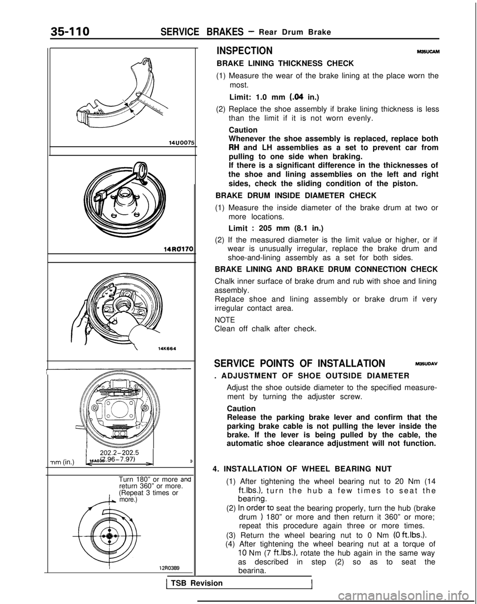
INSPECTIONM36UCAM
BRAKE LINING THICKNESS CHECK
(1) Measure the wear of the brake lining at the place worn the most.
Limit: 1.0 mm
(84 in.)
(2) Replace the shoe assembly if brake lining thickness is less than the limit if it is not worn evenly.
Caution
Whenever the shoe assembly is replaced, replace both
RH and LH assemblies as a set to prevent car from
pulling to one side when braking.
If there is a significant difference in the thicknesses of
the shoe and lining assemblies on the left and right
sides, check the sliding condition of the piston.
BRAKE DRUM INSIDE DIAMETER CHECK
(1) Measure the inside diameter of the brake drum at two or more locations.
Limit
:205 mm (8.1 in.)
(2) If the measured diameter is the limit value or higher, or if wear is unusually irregular, replace the brake drum and
shoe-and-lining assembly as a set for both sides.
BRAKE LINING AND BRAKE DRUM CONNECTION CHECK
Chalk inner surface of brake drum and rub with shoe and lining
assembly. Replace shoe and lining assembly or brake drum if very
irregular contact area.
NOTE
Clean off chalk after check.
SERVICE POINTS OF INSTALLATION M35UDAV
. ADJUSTMENT OF SHOE OUTSIDE DIAMETER Adjust the shoe outside diameter to the specified measure-ment by turning the adjuster screw.
Caution
Release the parking brake lever and confirm that the
parking brake cable is not pulling the lever inside the
brake. If the lever is being pulled by the cable, the
automatic shoe clearance adjustment will not function.
4. INSTALLATION OF WHEEL BEARING NUT (1) After tightening the wheel bearing nut to 20 Nm (14 ft.lbs.),
turn the hub a few times to seat the
(2)
~~~~~‘to seat the bearing properly, turn the hub (brake
drum
) 180” or more and then return it 360” or more;
repeat this procedure again three or more times.
(3) Return the wheel bearing nut to 0 Nm
(0 ftlbs.).
(4) After tightening the wheel bearing nut at a torque of
10 Nm (7 ft.1b.s.). rotate the hub again in the same way
as described in step (2) so as to seat the bearina.
1 TSB Revision
Page 1232 of 1273
SERVICE BRAKES - Rear Drum Brake/Rear Brake Wheel Cylinder35-I 11
(5) Then once again tighten the wheel bearing nut to 10
Nm (7
ft.lbs.).
(6) Install the lock cap and split pin.
(7) If the position of the cotter pin is not matched with the
holes of the lock cap, reposition the lock cap so that the
holes align. If this can not be accomplished, back off the
nut by not more than 15”.
Caution
Check to be sure that the lock nut cannot b
e
loosened manually.
(8) After setting the split pin in place, seat the bearing in the same manner as in step (2).
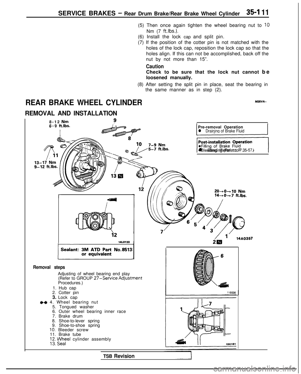
REAR BRAKE WHEEL CYLINDER
REMOVAL AND INSTALLATION
8-12 Nm?6-9 ft.lbs./
-
r
14LO122
plant: ~AA;;~~n’: No.8513
Removal steps
Adjusting of wheel bearing end play (Refer to GROUP 27-Service AdjustmentProcedures.)
1. Hub cap
2. Cotter pin
3. Lock cap
~~ 4. Wheel bearing nut
5. Tongued washer
6. Outer wheel bearing inner race
7. Brake drum
8. Shoe-to-lever spring
9. Shoe-to-shoe spring
10. Bleeder screw
11. Brake tube
VI Fezel cylinder assembly
IPre-removal Operationl Draininq of Brake FluidI
‘+iGJq
l Bleeding (Refer to P.35-57.)
20-+0+10 Nm 14-+0-+7
fklbs.
2& ‘. 14A0357
TSB Revision
Page 1260 of 1273
PARKING BRAKES - Parking Brake Cable
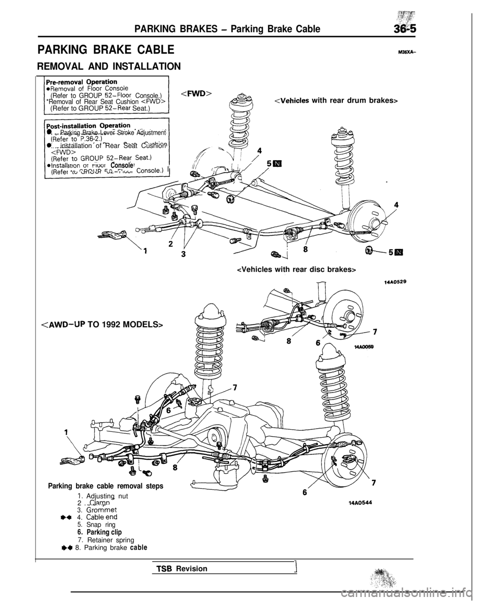
PARKING BRAKE CABLE
REMOVAL AND INSTALLATION
~$y$y$Y&
M36xA-
(Refer to GROUP 52-Floor Console.)
*Removal of Rear Seat Cushion
Seat.)
l Parking Brake Lever Stroke Adjustment
l installation of Rear Seat Cushion
3y_on,“6,:;;0; ConsoleA rl-~IIll(77 I i /
:/AWD-UP TO 1992 MODELS>
Parking brake cable removal steps
1. Adjusting nut
2. Clamn
-3.Gromrmet+44. Cableend5.Snap ring6.
Parking clip
7.Retainer spring++ 8. Parking brake cable
14A0544
14AO529 TSB
Revision
1
Page 1261 of 1273
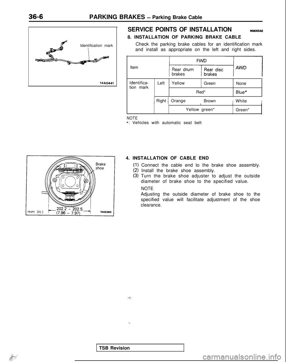
36-6PARKING BRAKES - Parking Brake Cable
Identification mark
14A0441
SERVICE POINTS OF INSTALLATIONWXDAE
8. INSTALLATION OF PARKING BRAKE CABLE Check the parking brake cables for an identification mark
and install as appropriate on the left and right sides.
Item Identifica-
tion mark Left
Yellow
Green None
Red*
Blue*
1 Right 1 Orange BrownIWhiteI I
Yellow green* I
Green*
NOTE*: Vehicles with automatic seat belt
4. INSTALLATION OF CABLE END
(1) Connect the cable end to the brake shoe assembly.
(2) Install the brake shoe assembly.
(3) Turn the brake shoe adjuster to adjust the outside diameter of brake shoe to the specified value.
NOTE
Adjusting the outside diameter of brake shoe to thespecified value will facilitate adjustment of the shoe
clearance. .‘,,
I.**i:,1;q ,.’
TSB Revision