oil filter MITSUBISHI GALANT 1989 Service Owner's Manual
[x] Cancel search | Manufacturer: MITSUBISHI, Model Year: 1989, Model line: GALANT, Model: MITSUBISHI GALANT 1989Pages: 1273, PDF Size: 37.62 MB
Page 763 of 1273
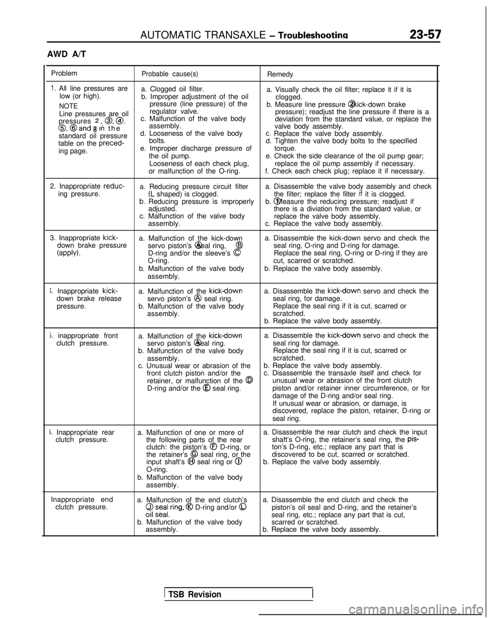
AUTOMATIC TRANSAXLE - Troubleshootinn
23-57
AWD A/T
Problem
Probable cause(s)Remedy
1. All line pressures are a. Clogged oil filter.
low (or high). a. Visually check the oil filter; replace it if it is
b. Improper adjustment of the oil clogged.
NOTEpressure (line pressure) of the
b. Measure line pressure @ (kick-down brake
Line pressures are oil regulator valve.
pressure); readjust the line pressure if there is a
pressures
2 ,, 0, @,
8 c. Malfunction of the valve body
deviation from the standard value, or replace the0, @and 7 In th
e
assembly.
valve body assembly.
standard oil pressure d. Looseness of the valve body
c. Replace the valve body assembly.
table on the preced-
bolts.
d. Tighten the valve body bolts to the specified
ing page. e. Improper discharge pressure of
torque.
the oil pump. e. Check the side clearance of the oil pump gear;
Looseness of each check plug, replace the oil pump assembly if necessary.
or malfunction of the O-ring. f. Check each check plug; replace it if necessary.
2. Inappropriate reduc-
a. Reducing pressure circuit filter a. Disassemble the valve body assembly and check
ing pressure.
(L shaped) is clogged. the filter; replace the filter if
it is clogged.b. Reducing pressure is improperly b. @ Measure the reducing pressure; readjust if
adjusted. there is a diviation from the standard value, or
c. Malfunction of the valve body replace the valve body assembly.
assembly. c. Replace the valve body assembly.
3. Inappropriate kick-
a. Malfunction of the kick-down a. Disassemble the kick-down servo and check the
down brake pressure servo piston’s @ seal ring,
43seal ring, O-ring and D-ring for damage.
(appb).D-ring and/or the sleeve’s 0Replace the seal ring, O-ring or D-ring if they are
O-ring. cut, scarred or scratched.
b. Malfunction of the valve body b. Replace the valve body assembly.
assembly.
1. Inappropriate kick-
down brake release
pressure. a. Malfunction of the kickdownservo piston’s @
seal ring.
b. Malfunction of the valve body assembly. a. Disassemble the kickdown servo and check the
seal ring, for damage. Replace the seal ring if it is cut, scarred or
scratched.
b. Replace the valve body assembly.
j. inappropriate front clutch pressure. a. Malfunction of the kickdowna. Disassemble the kickdown servo and check the
servo piston’s @ seal ring.
seal ring for damage.
b. Malfunction of the valve body Replace the seal ring if it is cut, scarred or
assembly. scratched.
c. Unusual wear or abrasion of the b. Replace the valve body assembly.
front clutch piston and/or the c. Disassemble the transaxle itself and check for
retainer, or malfunction of the
0unusual wear or abrasion of the front clutch
D-ring and/or the @
seal ring. piston and/or retainer inner circumference, or for
damage of the D-ring and/or seal ring.
If unusual wear or abrasion, or damage, is
discovered, replace the piston, retainer, D-ring or
seal ring.
j. Inappropriate rear clutch pressure. a. Malfunction of one or more of
the following parts of the rearclutch: the piston’s
@I D-ring, or
the retainer’s 68 seal ring, or the
input shaft’s @I seal ring or @
O-ring.
b. Malfunction of the valve body assembly. a. Disassemble the rear clutch and check the input
shaft’s O-ring, the retainer’s seal ring, the pis-
ton’s D-ring, etc.; replace any part that is
discovered to be cut, scarred or scratched.
b. Replace the valve body assembly.
Inappropriate end clutch pressure. a. Malfunction of the end clutch’s
($ z;ea/,ring, @I D-ring and/or 0
b. Malfunction of the valve body
assembly. a. Disassemble the end clutch and check the
piston’s oil seal and D-ring, and the retainer’s
seal ring, etc.; replace any part that is cut,
scarred or scratched.
b. Replace the valve body assembly.
1 TSB Revision
Page 794 of 1273
23-88AUTOMATIC TRANSAXLE - Service Adjustment Procedures
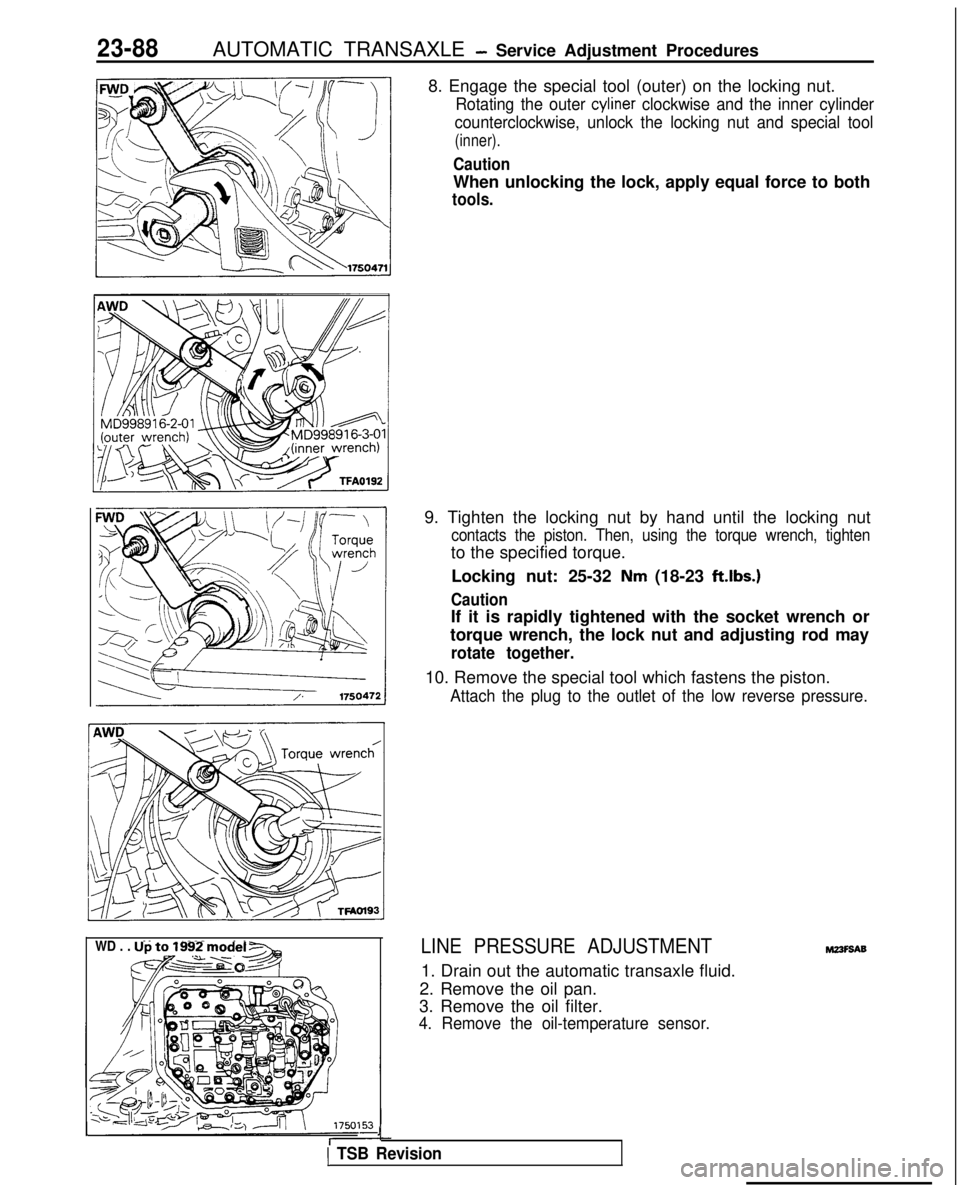
8. Engage the special tool (outer) on the locking nut.
Rotating the outer cyliner clockwise and the inner cylinder
counterclockwise, unlock the locking nut and special tool
(inner).
Caution
When unlocking the lock, apply equal force to both
tools.
WD . . . Up to 1992 model -
&@~o-&q
9. Tighten the locking nut by hand until the locking nut
contacts the piston. Then, using the torque wrench, tighten
to the specified torque.
Locking nut: 25-32
Nm (18-23 ft.lbs.)
Caution
If it is rapidly tightened with the socket wrench or
torque wrench, the lock nut and adjusting rod may
rotate together.
10. Remove the special tool which fastens the piston.
Attach the plug to the outlet of the low reverse pressure.
LINE PRESSURE ADJUSTMENT
1. Drain out the automatic transaxle fluid.
2. Remove the oil pan.
3. Remove the oil filter.
4. Remove the oil-temperature sensor.
J
1 TSB Revision
M23F9A9
Page 797 of 1273
AUTOMATIC TRANSAXLE -Service Adjustment Procedures23-91
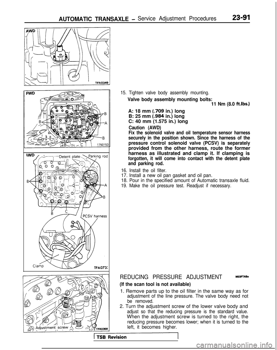
15. Tighten valve body assembly mounting.
Valve body assembly mounting bolts:11 Nm (8.0 ftlbs.)
A: 18 mm (.709
in.) long
B: 25 mm (.984
in.) long
C: 40 mm (1.575 in.) long
Caution (AWD)
Fix the solenoid valve and oil temperature sensor harness
securely in the position shown. Since the harness of the
pressure control solenoid valve (PCSV) is separately
provided from the other harness, route the former
harness as illustrated and clamp it. If clamping is
forgotten, it will come into contact with the detent plate and parking rod.
16. Install the oil filter.
17. Install a new oil pan gasket and oil pan.
18. Pour in the specified amount of Automatic transaxle fluid.
19. Make the oil pressure test. Readjust if necessary.
REDUCING PRESSURE ADJUSTMENTMZ3FTAb
(If the scan tool is not available)
1. Remove parts up to the oil filter in the same way as for
adjustment of the line pressure. The valve body need not
be removed.
2. Turn the adjustment screw of the lower valve body and
adjust so that the reducing pressure is the standard value.
When the adjustment screw is turned to the right, the
reducing pressure becomes lower; when it is turned to the
left, it becomes higher.
Page 798 of 1273
23-92AUTOMATIC TRANSAXLE - Service Adjustment Procedures
NOTE
When adjusting the reducing pressure, aim for the center
value (425 kPa, 60 psi) of the standard value allowance.
Standard value: 415-435
kPa (59-62 psi)
Oil pressure change for each turn of adjustment screw: 22
kPa (3.1 psi) . . . FWD (Up to MODEL 1990)
45
kPa (6.4 psi) . . . FWD (From MODEL 1990.5, AWD)
3. Install the oil filter and oil pan in the same way as for adjustment of the line pressure.
4. Make the oil pressure test. Readjust if necessary.
(If the scan tool is used)
1. Using the scan tool, forcibly drive the pressure control
solenoid valve at 50% duty, and measure the kick-down
brake apply pressure.
If the kick-down brake apply pressure does not exist within
the standard value width, adjust the pressure with the
reducing pressure adjustment screw.
Standard value: 275 + 10 kPa (39 + 1 psi)
Oil pressure change for each turn of adjustment screw:
25 kPa (3.6 psi) FWD (Up to MODEL 1990)
22
kPa (3.1 psi) FWD (From MODEL 1990.5), AWD
2. Check to be sure that the reducing pressure (after the
adjustment is completed) is within the range of 360-480
kPa (51 -68 psi.).
Caution
This adjustment should be made at an oil
temperature
of 70- 80°C
(160- 180°F).
If the adjustment is made at a temperature that is too
high, the line pressure will drop during idling, with the
result that it might not be possible to make the correct
adjustment.
I / Oii
seal09K561
THROTTLE-POSITION SENSOR ADJUSTMEF&
Refer to GROUP 13-On-Vehicle Inspection of MFI Compo-
nents.
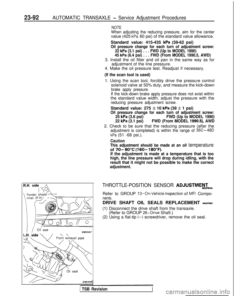
DRIVE SHAFT OIL SEALS REPLACEMENT MZ3FDBC
(1) Disconnect the drive shaft from the transaxle. (Refer to GROUP 26-Drive
Shaft.)
(2) Using a flat-tip
(-) screwdriver, remove the oil seal.
1 TSB Revision1
Page 1178 of 1273
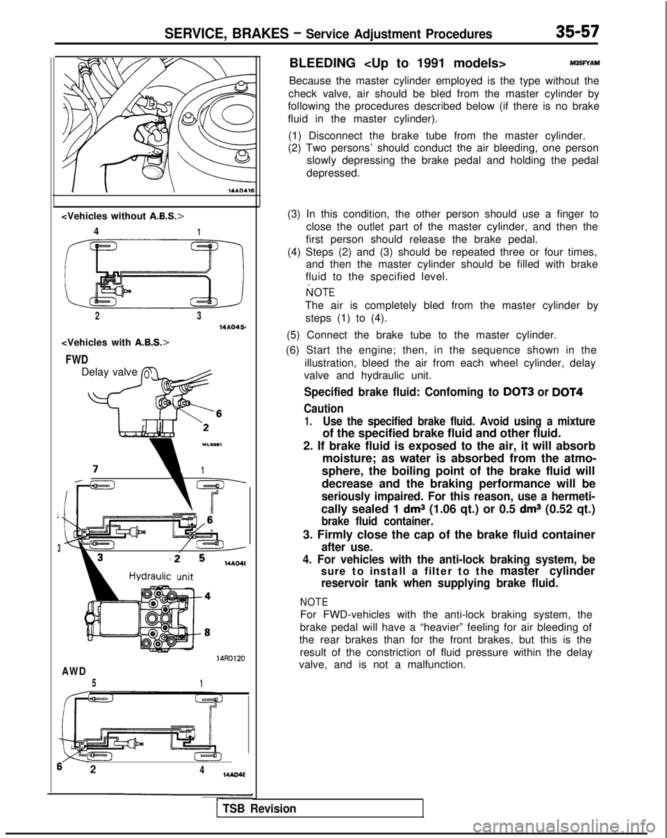
SERVICE, BRAKES - Service Adjustment Procedures35-57
4
1
2314AQ456
FWD
Delay valve L
flc ’
-c
i1
L
3
14AO4l
mit
14RD120
AWD
51
6 2414AO4E
BLEEDING
Because the master cylinder employed is the type without the
check valve, air should be bled from the master cylinder by
following the procedures described below (if there is no brake
fluid in the master cylinder).
(1) Disconnect the brake tube from the master cylinder.
(2) Two persons’ should conduct the air bleeding, one person
slowly depressing the brake pedal and holding the pedal
depressed.
(3) In this condition, the other person should use a finger to close the outlet part of the master cylinder, and then the
first person should release the brake pedal.
(4) Steps (2) and (3) should be repeated three or four times, and then the master cylinder should be filled with brake
fluid to the specified level.
I(]OTE
The air is completely bled from the master cylinder by
steps (1) to (4).
(5) Connect the brake tube to the master cylinder.
(6) Start the engine; then, in the sequence shown in the illustration, bleed the air from each wheel cylinder, delay
valve and hydraulic unit.
Specified brake fluid: Confoming to DOT3 or DOT4
Caution
1.Use the specified brake fluid. Avoid using a mixture
of the specified brake fluid and other fluid.
2. If brake fluid is exposed to the air, it will absorb moisture; as water is absorbed from the atmo-
sphere, the boiling point of the brake fluid will
decrease and the braking performance will be
seriously impaired. For this reason, use a hermeti-
cally sealed 1 dms (1.06 qt.) or 0.5 dms (0.52 qt.)
brake fluid container.
3. Firmly close the cap of the brake fluid container
after use.
4. For vehicles with the anti-lock braking system, be
sure to install a filter to the master cylinder
reservoir tank when supplying brake fluid.
NOTE
For FWD-vehicles with the anti-lock braking system, the
brake pedal will have a “heavier” feeling for air bleeding of
the rear brakes than for the front brakes, but this is the
result of the constriction of fluid pressure within the delay
valve, and is not a malfunction.
1 TSB Revision
Page 1264 of 1273
ALPHABETICAL INDEX3
DISC BRAKEFront
......................................
.
35-94-I
Rear......................................
.
35-114-l
DlSC BRAKE PADS. Marntenance.......................
.
00-44-j
DWHARGlNG
SYSTEM ......................... 55-26-l
DISJRIBUTOR..............................
.
16-55-11
DOoR
........................................
42-74-lDOOR. Fit Adjustment
..............................
. 42-51-l
DOOR DRIP LINE WEATHERSTRIP
Front.......
.
........................... 42-112-j
Rear.....................................
.
42-114-IDOOR GLASS
Adjustment
...............................
42-52-f
Front..................................
.
42-80-l
Rear ........... 42-83-I
DOOR HANDLE
Front
...........
.
........ ............ 42-96-l
Rear.
.................. ................. 42-99-l
DOOR INSIDE HANDLE, Play Check.....................
.
42-52-l
DOOR LATCH
Front
.........
.
............... ........ 42-96-l
Rear.................................
. 42-99-l
DOOR MIRROR...............................
.
51-33-1
DOOR
MOULDING
Front
....................................
.
42-112-l
Rear......................................
.
42-114-l
DOOR REGULATOR
Front
......................................
.
42-80-I
Rear...............
.
.................... 42-83-l
DOOR RUNCHANNEL..........................
.
42-l 10-l
DOOR TRIM
Front
......................................
.
42-76-l
Rear.......................................
.
42-78-i
DOOR WATERPROOF FILM
Fron
t
.................................... 42-76-l
Rear........................................
.
42-78-l
DRIVE BELT
Compressor, Adjustment
....................
.
55-17-l
Tension Adjustment
Tension Adjustment
Water Pump and Generator, Maintenance ..............
00-41 -IDRIVE SHAFTFront Axle
.....................................
. 26-12-l
Rear
Axle
. 27-20-I
DRIVE SHAFT BOOTS, Maintenance....................
.
00-45-j
DRIVE SHAFT OIL SEALSReplacement
...........................
.
23-92-I
Replacement
.
22-18-l
Replacement
.
22-4-l
DRUMBrake, inside Diameter, Check
......................
.
35-67-j
Brake,
Rear..............................
.
..... 35-108-l
DRUM BRAKE, Rear
................................
.
35-108-1
DRUM BRAKE LININGS, Rear, Maintenance
..............
.
06-44-j
DRYER........................................
.
33B-127-l
E
EGR SOLENOID
.................................
.
17-28-j
On-vehicle
Inspection
On-vehicle
Inspection
.
13-101-t
On-vehicle
Inspection
.
13-191-l
EGR SYSTEM
speccon
.
17-25-j inspection
.
17-25-1
EGR TEMPERATURE SENSOR
Emission Control
................................
.
17-28-l
On-vehicle Inspection
On-vehicle Inspection
On-vehicle
Inspection
.
13-177-l
EGRVALVE........................................
.
17-27-f
EGR VALVE CONTROL VACUUM
.......................
.
17-26-l
ELECTRONIC CONTROL UNIT
35-134-jELEMENT
Air Cleaner. Inspection
and Replacement ................ 15-6-l
Air Cleaner, Maintenance ........................... go-39-j
END PLAY
Hub.
Inspection
.
33B-86-l
Hub. Inspection
.
26-5-l
Rear. Wheel Bearing, Adjustment
.
27-3-l
Rear Wheel Bearing. Check
.
27-15-i
ENGINE
DOHC
.......................................
.
11-63-l
SOHC.......................................
.
11-14-1
ENGINE CONTROL................................
.
13-328-l
ENGINE CONTROL MODULE POWER GROUND
On-vehicle Inspectron
..................
.
13-257-l
On-vehicle Inspection
.
13-45-l
On-vehicle Inspection
.
13-146-1
ENGINE CONTROL MODULE TERMINAL VOLTAGE
On-vehicle Inspection
.
13-315-I
On-vehicle Inspection
On-vehicle Inspection
.
13-192-l
ENGINE COOLANT
Concentration Test
....
.
............................
14-8-l LeakCheck
....................................... 14-8-l
Maintenance ..................................... 00-44-I
Replacement ..............................
,......
.
14-8-I
ENGINE COOLANT TEMPERATURE GAUGE UNIT.........
. 14-31-l
ENGINE COOLANT TEMPERATURE SENSOR
Cooling
........................................
. 14-31-I
Emission Control .................................. 17-21-l
On-vehicle Inspection
On-vehicle Inspection
.
13-55-j
On-vehicle Inspection
.
13-155-l
ENGINE COOLANT TEMPERATURE SWITCH
Cooling........................................
. 14-31-I
Heater, Air Conditioning and Ventilation ......... 55-57-l
ENGINE MOUNTING..................................
.
32-4-l
ENGINE OILCheck
................................
.
11-57-j
Check
. 11-7-l
Maintenance .....................................
00-41-1
ENGINE OIL FILTER, Maintenance ......................
.
60-41-j
ENGINE RPLL
STOPPER..............................
.
32-6-j
EPS CONTROL UNIT................................
.
37A-59-l
EPS MODE SELECTOR SWITCH.......................
.
37A-59-j
EpS SOLENOID, Check
..............................
.
37A-19-j
EVAPORATIVE EMISSION CANISTER...................
.
77-21-j
EVAPORATIVE EMISSION CONTROL SYSTEM............
.
17-15-l
EVAPORATIVE EMISSION PURGE SOLENOIDEmission Control
.................................
.
17-21-1
On-vehicle
Inspection
, 13-307-I
On-vehicle
Inspection
.
13-99-1
On-v&i&
inspection
........... 13-189-j
EVAPORATOR....
.
................................ 55-34-f
EXHAUST GAS RECIRCULATION (EGR) SYSTEM..........
.
17-22-I
EXHAUST MANIFOLD
DOHC-Non-Turbo................................
.
15-30-1
Page 1265 of 1273
4ALPHABETICAL INDEX
DOHC-Turbo.................................
. 15-31-f
SOHC-8VALVE..................................
.
15-27-t
SOHC-1 GVALVE............................
.
15-28-l
EXHAUST PIPEDOH
C
......................... 15-33-I
SOHC.....................................
.
15-32-l
EXHAUST SYSTEM, Maintenance ..................... 00-45-I
F
FAN MOTOR
Condenser
.............................
.
55-48-l
Radiator...................
.
......... 14-12-I
FEEDER CABLE ..........................
54-l 55-11FENDER................................
.
42-61-t
FILLER DOOR, Fuel Tank.........................
.
42-60-I
FILLER TUBE CAP, Fuel Tank, Inspection...............
.
17-21 -I
FILTER
Engine 011. Maintenance ....................
. 00-41-I
Fuel
Fuel
.
...................
13-I 15-lFuel
.
13-195
FITTINGS, Handling................................
. 55-22-l
FIXED SAS
Adjustment
........................
.
13-250-I
Adjustment
.
13-138-I
FLAT BATTERY, Remedy............................
.
35-75-l
FLOOR CONSOLE................................
.
52-29-l
FLUID
Power Steering, Level Check
...................
. 37A-21-l
Power Steering, Replacement ................. 37A-21-l
Transaxle, Replacement ..................... 23-82-l
FLUID LEVEL, Transaxle, Inspection .................. 23-82-l
FOG LIGHT................
.
......................
54-94-11FOG LIGHT SWITCH................................
.
54-99-114WS, Function Check
..........................
. 37B-6-l
FRONT BRAKE DISC
Run-out Check
...................................
. 35-63-I
Run-out Correction ........................... 35-64-l
Thickness Check .............................. 35-65-l
FRONT DISC BRAKE.................................
. 35-94-l
FRONT DISC BRAKE PAD, Check and Replacement ......... 35-59-l
FRONT DOOR DRIP LINE WEATHERSTRIP 42-112-I
FRONT DOOR GLASS...............................
. 42-80-l
FRONT DOOR HANDLE.........................
. 42-96-l
FRONT DOOR LATCH...
.
......... .......... 42-96-l
FRONT DOOR
MOULDING
........................... 42-112-I
FRONT DOOR REGULATOR........................
. 42-80-I
FRONT DOOR TRIM.................................
. 42-76-l
FRONT DOOR WATERPROOF FILM....................
. 42-76-l
FRONT GRILLE..................................
. 51-12-l
FRONT SEAT,...................................
. 52-35-l
FRONT WHEEL ALIGNMENT Adjustment
. 338-86-I
Adjustment
FUEL FILTER
DOHC
.......................................
. 13-327-I
SOHC-8VALVE
.................................
13-l 15-l SOHC-IGVALVE
................................ 13-195-I
FUEL HOSES, Maintenance ............................
00-39-1
FUEL LINE
DOHC-AWD ..................................
.
13-326-l
DOHC-FWD....................................
.
13-324-l
SOHC-8VALVE
................................. 13-113-l
SOHC-1 ~VALVE............................
.
13-l 95-IFUEL PRESSURE
On-vehicle Inspection
On-vehicle Inspection
On-vehicle Inspection
FUEL PRESSURE SOLENOID
On-vehicle Inspection
FUEL PUMP
On-vehicle Inspection
On-vehicle Inspection
On-vehicle Inspection
FUEL SYSTEM, Maintenanc
e
FUEL TANK
DOHC-AWD .,.......
DOHC-FW
D
SOHC-8VALVE
SOHC-16VALVE
FUEL TANK FILLER DOO
R
FUEL TANK FILLER TUBE CAP, Inspection
FUEL TANK PRESSURE CONTROL VALVE. 13-312-l
13-102-I
,.....13-I
92-l
13-307-I
......
13-258-l
....... 13-46-l
...... 13-147-l
....... 00-39-l
......
13-322-l
...... 13-318-l
..... 13-109-I
...... 13-195-I
....... 42-60-I
....... 17-21-I
....... 17-21-l
G
GARNISHES
51-13-l
GASKET
Cylinder Head
Cylinder Head
GAUGE UNIT, Engine Coolant Temperature
14-31-l
GEAR BOX, Power Steering 37A-32-l
GEAR OIL, Level Check
GENERATOR
16-g-11
GLASS
Door, Adjustmen
t
42-52-l
Door, Front 42-80-I
Door, Rear 42-83-l
Quarter Window 42-70-I
Window.............
.._......_...... 42-63-i
Window,Rear
42-72-i
GRILLE,Front
_. _. _.
51-12-l
G-SENSOR
Service Brakes
35-132-l
Output Voltage, Check 336-96-l
H
HANDLE
Door, Front
..........................
.
Door,Rear
...........................
Door Inside, Play Check. ..................
HAZARD SWITCH.........................
.
HEADLIGHTS............................
.
HEADLINING.............................
.
HEATED OXYGEN SENSOR, On-vehicle Inspection
>
...............................
HEATER CONTROL.......................
.
HEATER UNIT............................
.
HEIGHT SENSOR.........................
.
HIGH MOUNTED STOP LIGHT...............
.
42-96-1 42-99-l
42-52-l
54-98-11
54-92-11
52-31-l
13-290-I
55-25-l
55-30-I
338-l
35-l
54-96-11HIGH PRESSURE SWITCH (HIGH-PRESSURE TANK SIDE),Actuation Pressure Check. 338-94-I
16-42-11
42-55-l
42-50-I
54-l 03-11
54-105-11
HIGH TENSION CABLE, Spark Test
HOOD .__...._..._......__._...................
HOOD, Alignment Adjustment .
HOR
N
. . . . . . . . . . . . . . . . . . . . . . . . . . . . . . . . . . . . \
. . . HORNRELAY
._.._._....___.........__.._._..___
HOSE
Brake, Maintenance
.
00-45-I
Page 1267 of 1273
6ALPHABETICAL INDEX
LOW PRESSURE SWITCH (LOW-PRESSURE TANK SIDE)
Actuation Pressure Check
.
M
MAIN MUFFLER
DOH
C
SOHC
MANIFOLD
Exhaust
Exhaust
Exhaust
Exhaust
Intake
Intake
Intake
Vacuum Inspection
Vacuum Inspection
MANUAL TRANSAXLE
AWD
FW
D
Maintenance
MASTER CYLINDER
Clutch
Service Brakes.
METER, Boost, On-vehrcle
Inspectron
METERS AND GAUGES
MIRROR, Door
MIRROR SWITCH. Remote Controlled
MIXTURE CONTROL [MFI) SYSTEM : : : : : :
MODE SELECTOR SWITCH EPS
MOTOR 15-30-I
15-31 -I
15-27-l
15-28-l
15-21-l
15-14-l
15-18-l
11-60-I
11-9-l
22-l 5-l
22-2-i
00-42-l
21-12-l
35-81 -I
13-311-I
54-8-11
51-33-l
51-34-l
17-29-l
37A-59-l
Idle Arr Control (DC Motor), On-vehicle Inspection
Idle Air Control (Stepper Motor), On-vehicle Inspection
Idle Speed Control (DC Motor),
6n-vehicle
Inspection
Starte
r
MOULDING
Door. Front
Door. Rear
Exterio
r
MOUNTING 42-112-l
42-1 14-l
51-15-l
Engine.
,,,.....
Transaxl
e
MUFFLER
Main
Main
> 32-4-l
32-5-l
15-33-l
15-32-I
N
NOISE. Compressor, Adjustmen
t
NORMAL VEHICLE HEIGHT, Check and Adjustment
OIL 55-23-l
338-88-I
0
Engine. Check
Engine. Check
1 : : 1 : 1
Engine, Maintenance.
.
Transaxle. Replacement
Transaxle. Replacement
Transfer. Replacemen
t
OIL COOLER HOSES, Transaxle
OIL FILTER, Engine, Maintenance. 11-57-l
11-7-l
00-41-I
22-18-l
22-4-l
23-82-l
23-l
00-l
00-41 -I338-95-I
15-33-l
15-32-l
13-l
84-l
13-298-l
13-93-l
16-19-f
OIL LEVEL
Gear, Check
.
27-l 5-f
Transaxle, Inspection
. 22-17-l
Transaxle, Inspection
. 22-4-l
Transfer, Inspection ............................... 23-82-l
OIL LINE, Rear. .............. ..................... 378-13-I
OIL PAN
DOHC.....................................
. 11-71-l
SOHC......
.
.................................. 11-23-l
OIL PRESSURE SWITCH, Power Steering. Check ........... 37A-24-l
OIL PUMP Power Steering ................................. 37A-48-l
Power Steering, Pressure Test ...................... 37A-23-l
Rear..........
.
...
......................... 378-15-I
...
Rear, Discharge Flow Volume Check .................. 378-6-I “s
OIL SCREEN.
DOHC.....................................
.
11-71-l
SOHC.
......................................
.
1 l-23-l
OIL SEALS Camshaft
Camshaft
........................... 11-19-l
Drive Shaft. Replacement .................... 23-92-l
Drive Shaft, Replacement
. 22-18-l
Drive Shaft, Replacement
. 22-4-l
Transfer, Replacement
. 22-19-l
OUTPUT VOLTAGE,
G sensor, Check ..................
. 33B-96-l
OXYGEN SENSOR
On-vehicle
inspectron
.
13-87-l
On-vehicle Inspection
. 13-179-l
P
PAD
Disc Brake. Front, Check and Replacement ............
. 35-59-l
Disc Brake. Maintenance. ........................... 00-44-i
Disc Brake. Rear, Check and Replacement
’.............
. 35-65-l
PANEL. Loose ....................................... 42-62-l
PARKING BRAKE CABLE..............................
. 36-5-l
PARKING BRAKE LEVER...............................
. 36-4-l
PARKING BRAKE LEVER, Stroke Check...................
. 36-2-l
PARKING BRAKE SWITCH, Check.......................
. 36-3-l
PARK/NEUTRAL POSITION SWITCH
Adjustment ..................................... 23-84-l
On-vehrcle
Inspection
On-vehicle Inspection
On-vehicle Inspection
PCV VALVE, Inspection
................................ 17-14-l
PEDAL
Brake
..........................................
. 35-76-l
Brake, Inspection
and Adjustment
.................... 35-53-l
Clutch.........................................
. 21-7-l
Clutch. Inspection
and Adjustment
..................... 21-5-l
PERFORMANCE TEST...............................
. 55-21-l
PIPE
Exhaust
Exhaust
. 15-32-l
Water
....................... 14-26-l
Water
. 14-28-l
Water
. 14-23-l
PLAY
End. Hub, Inspection
End. Hub. Inspection
. 26-6-l
End, Rear Wheel Bearing, Check
. 27-3-l