differential MITSUBISHI GALANT 1989 Service Owner's Guide
[x] Cancel search | Manufacturer: MITSUBISHI, Model Year: 1989, Model line: GALANT, Model: MITSUBISHI GALANT 1989Pages: 1273, PDF Size: 37.62 MB
Page 1004 of 1273
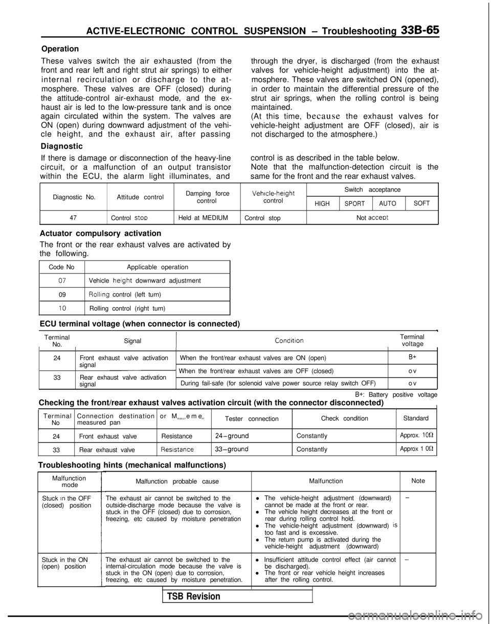
ACTIVE-ELECTRONIC CONTROL SUSPENSION - Troubleshooting 33B-65
Operation
These valves switch the air exhausted (from the
front and rear left and right strut air springs) to either internal recirculation or discharge to the at-
mosphere. These valves are OFF (closed) during
the attitude-control air-exhaust mode, and the ex- haust air is led to the low-pressure tank and is once
again circulated within the system. The valves are
ON (open) during downward adjustment of the vehi-
cle height, and the exhaust air, after passing
Diagnostic through the dryer, is discharged (from the exhaust
valves for vehicle-height adjustment) into the at-
mosphere. These valves are switched ON (opened),
in order to maintain the differential pressure of the
strut air springs, when the rolling control is being maintained.
(At this time, because the exhaust valves for
vehicle-height adjustment are OFF (closed), air is not discharged to the atmosphere.)
If there is damage or disconnection of the heavy-line control is as described in the table below.
circuit, or a malfunction of an output transistor Note that the malfunction-detection circuit is the
within the ECU, the alarm light illuminates, and same for the front and the rear exhaust valves.
Damping force Vehrcle-height
Switch acceptance
Diagnostic No. Attitude control
controlcontrol
HIGHSPORTAUTOSOFT
47
Control stooHeld at MEDIUM Control stop Not acceot
Actuator compulsory activation
The front or the rear exhaust valves are activated by
the following.
Code No Applicable operation
07Vehicle height downward adjustment
09 Rollrng
control (left turn)
10Rolling control (right turn)
ECU terminal voltage (when connector is connected) Terminal No. Signal Terminal
voltage
24
33 Front exhaust valve activation
When the front/rear exhaust valves are ON (open)
B+signal~ When the front/rear exhaust valves are OFF (closed) o
v
Rear exhaust valve activation
signal During fail-safe (for solenoid valve power source relay switch OFF)
ov
B+: Battery positive voltage
Checking the front/rear exhaust valves activation circuit (with the con\
nector disconnected)
II ITerminal Connection destination or M
easurem
e
nt
No measured pan Tester connection
Check condition
Standard
I
24Front exhaust valve Resistance24-ground
33Rear exhaust valve Resistance33-ground
Troubleshooting hints (mechanical malfunctions)
Constantly
Constantly
Approx. 100
Approx 1
OQ
Malfunction mode
Stuck
In the OFF
(closed) position
Stuck in the ON
(open) position
I
Malfunction probable cause Malfunction
Note
The exhaust air cannot be switched to the outside-discharge mode because the valve is
stuck in the OFF (closed) due to corrosion,
freezing, etc caused by moisture penetration l The vehicle-height adjustment (downward)
-cannot be made at the front or rear.
l The vehicle height decreases at the front or
rear during rolling control hold.
l The vehicle-height adjustment (downward)
istoo fast and is excessive.
l The return pump is activated during the
vehicle-height adjustment (downward)
The exhaust air cannot be switched to the l Insufficient attitude control effect (air cannot
-internal-circulation mode because the valve is
be discharged).
stuck in the ON (open) due to corrosion, l
The front or rear vehicle height increases
freezing, etc caused by moisture penetration. after the rolling control.
TSB Revision
Page 1101 of 1273
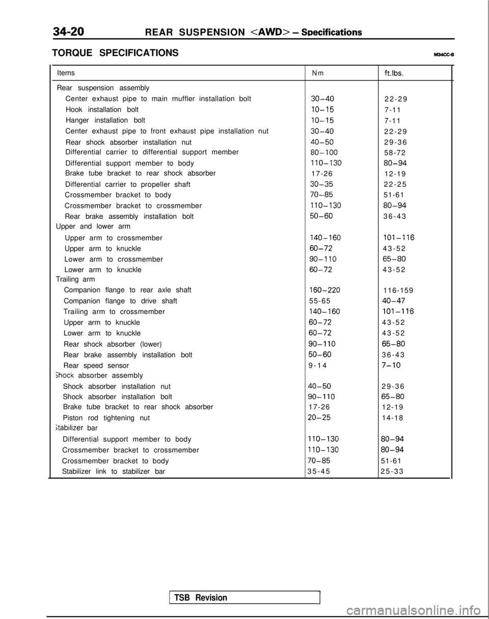
34-20
REAR SUSPENSION
TORQUE SPECIFICATIONSM34cGB
Items
Rear suspension assembly Center exhaust pipe to main muffler installation boltHook installation bolt
Hanger installation bolt
Center exhaust pipe to front exhaust pipe installation nut
Rear shock absorber installation nut
Differential carrier to differential support member
Differential support member to body
Brake tube bracket to rear shock absorber
Differential carrier to propeller shaft
Crossmember bracket to body
Crossmember bracket to crossmember Rear brake assembly installation bolt
Upper and lower arm
Upper arm to crossmember
Upper arm to knuckle
Lower arm to crossmember
Lower arm to knuckle
Trailing arm
Companion flange to rear axle shaft
Companion flange to drive shaft
Trailing arm to crossmember
Upper arm to knuckle
Lower arm to knuckle
Rear shock absorber (lower)
Rear brake assembly installation bolt
Rear speed sensor jhock
absorber assembly
Shock absorber installation nut
Shock absorber installation bolt Brake tube bracket to rear shock absorber
Piston rod tightening nut
itabilizer bar
Differential support member to body
Crossmember bracket to crossmember
Crossmember bracket to body
Stabilizer link to stabilizer bar
Nmftlbs.
30-4022-2
9
IO-157-11
IO-157-11
30-4022-2
9
40-5029-3
6
80-10058-72
110-13080-94
17-26
12-19
30-3522-2
5
70-8551-61
110-13080-94
50-6036-4
3
140-160101-116
60-7243-5
2
90-I 1065-80
60-7243-5
2
160-220116-159
55-65
40-47
140-160101-116
60-7243-5
2
60-7243-5
2
90-I 1065-80
50-6036-4
3
9-14
7-10
40-5029-3
6
90-I 1065-80
17-26
12-19
20-2514-18
110-13080-94
110-13080-94
70-8551-61
35-4
5
25-33
TSB Revision1
Page 1106 of 1273

REAR SUSPENSION
40-50 Nm
29-36 ftlbs.
80-100 N
m
58-72
ft.lbs.
22-25 ftlbs.
\
50-60Nm36-4
3
ftlbs.
70-85Nm70-85Nm110-130 Nm51-61ft.lbs.51-61ftlbs.80-94 ftlbs.
12AO619
9. Self locking nut
10. Differential support member
II. Crossmember bracket
12. Parking brake cable and rear speed sensor
installation bolt
13. Cable band
14. Rear speed sensor connector
15. O-ring
16. Rear suspension assembly
TSB Revision1
Page 1107 of 1273
34-26REAR SUSPENSION
I 412AOlOS
J
TSB Revision
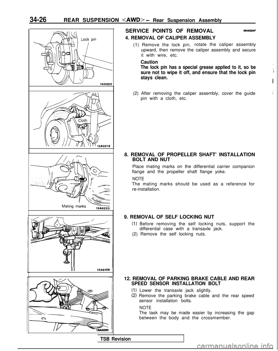
SERVICE POINTS OF REMOVAL
4. REMOVAL OF CALIPER ASSEMBLYM?dGSAP
(1) Remove the lock pin, rotate the caliper assembly
upward, then remove the caliper assembly and secure
it with wire, etc.
Caution
The lock pin has a special grease applied to it, so be
sure not to wipe it off, and ensure that the lock pin
stays clean.
I
(2) After removing the caliper assembly, cover the guide pin with a cloth, etc.
8. REMOVAL OF PROPELLER SHAFT’ INSTALLATION BOLT AND NUT
Place mating marks on the differential carrier companion
flange and the propeller shaft flange yoke.
NOTE
The mating marks should be used as a reference for
re-installation.
9. REMOVAL OF SELF LOCKING NUT
(1) Before removing the self locking nuts, support the differential case with a transaxle jack.
(2) Remove the self locking nuts.
12. REMOVAL OF PARKING BRAKE CABLE AND REAR
SPEED SENSOR INSTALLATION BOLT
(1) Lower the transaxle jack slightly.
(2) Remove the parking brake cable and the rear speed sensor installation bolts.
NOTE
The task may be made easier by increasing the gapbetween the body and the crossmember.
Page 1108 of 1273
REAR SUSPENSION
12A0222
12A.0221
,
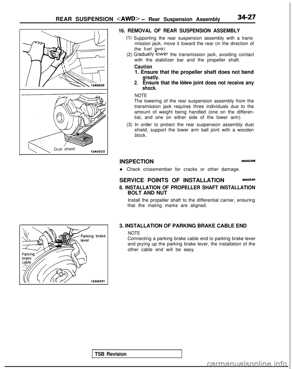
16. REMOVAL OF REAR SUSPENSION ASSEMBLY
(1) Supporting the rear suspension assembly with a trans-
mission jack, move it toward the rear (in the direction of
the fuel tank).
(2)
Graduallyibwer the transmission jack, avoiding contact
with the stabilizer bar and the propeller shaft.
Caution
1. Ensure that the propeller shaft does not bend
greatly.
2.Ensure that the liibro joint does not receive any
shock.
NOTE
The lowering of the rear suspension assembly from the
transmission jack requires three individuals due to the
amount of weight being handled (one on the differen-
tial, and one on either side of the lower arm).
(3) In order to protect the rear suspension assembly dust shield, support the lower arm ball joint with a wooden
block.
TSB Revision
INSPECTIONM24GCAM
l Check crossmember for cracks or other damage.
SERVICE POINTS OF INSTALLATION
M34GDAfl
8. INSTALLATION OF PROPELLER SHAFT INSTALLATION
BOLT AND NUT Install the propeller shaft to the differential carrier, ensuring
that the mating marks are aligned.
3. INSTALLATION OF PARKING BRAKE CABLE END
NOTE
Connecting a parking brake cable end to parking brake lever
and prying up the parking brake lever, the installation of the other cable end will be easy.
Page 1263 of 1273
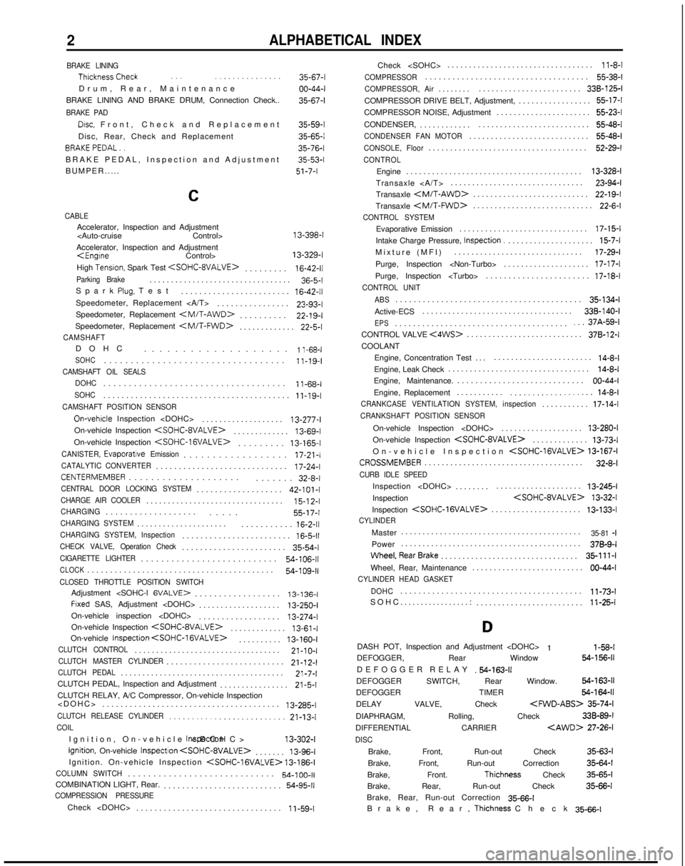
2ALPHABETICAL INDEX
BRAKE LINING ThicknessCheck
.., ..,............
Drum, Rear, Maintenanc
e
BRAKE LINING AND BRAKE DRUM, Connection Check..
BRAKE PAD
Drsc, Front, Check and Replacemen
t
Disc, Rear, Check and Replacement BRAKEPEDAL..
BRAKE PEDAL, Inspection and Adjustment
BUMPER..... 35-67-l
00-44-l
35-67-l
35-59-l
35-65-l
35-76-l
35-53-l
51-7-I
C
CABLEAccelerator, Inspection and Adjustment
Accelerator, Inspection and Adjustment
High
Tensron, Spark Test
.
16-42-11Parking Brake................................
.
36-5-l
Spark
Plug, Tes
t
........................
16-42-11Speedometer, Replacement ...............
.
23-93-l
Speedometer, Replacement
.
22-19-I
Speedometer, Replacement
.
22-5-l
CAMSHAFTDOH
C
...................
1 l-68-lSOHC.................................
.
11-19-I
CAMSHAFT OIL SEALS
DOHC
...................................
.
11-68-I
SOHC........................................
.
11-19-I
CAMSHAFT POSITION SENSOR
On-vehrcle Inspection
..................
.
13-277-l
On-vehicle Inspection
.
13-69-l
On-vehicle Inspection
.
13-165-I
CANISTER,
Evaporatjve Emission.................
.
17-21-l
CATALYTIC CONVERTER............................
.
17-24-l
CENTERMEMBER...................
.
....... 32-8-l
CENTRAL DOOR LOCKING SYSTEM..................
.
42-101-I
CHARGE AIR COOLER...............................
.
15-l
2-l
CHARGING..................
.
..... 55-17-I
CHARGING SYSTEM....................
.
...........
16-2-11CHARGING SYSTEM, Inspection.......................
.
16-5-11CHECK VALVE, Operation Check......................
.
35-54-l
CIGARETTE LIGHTER..........................
.
54-106-11
CLOCK........................................
.
54-109-11CLOSED THROTTLE POSITION SWITCHAdjustment
.................. 13-136-I
Frxed SAS, Adjustment
..................
.
13-250-I
On-vehicle inspection
On-vehicle Inspection
.
13-61-I
On-vehicle Inspection
. 13-160-I
CLUTCH CONTROL.................................
.
21-10-I
CLUTCH MASTER CYLINDER.........................
.
21-12-l
CLUTCH PEDAL.....................................
.
21-7-l
CLUTCH PEDAL, Inspection and Adjustment ................
21-5-1CLUTCH RELAY, A/C Compressor, On-vehicle Inspection
....................................... 13-285-l
CLUTCH RELEASE CYLINDER.........................
21-13-lCOIL
Ignition, On-vehicle
Inspectron
Ignition, On-vehicle
InspectIon
. 13-96-l
Ignition. On-vehicle Inspection
COLUMN SWITCH............................
.
54-100-11COMBINATION LIGHT, Rear.
.........................
.
54-95-11COMPRESSION PRESSURE
Check
...............................
.
1
i-59-1Check
..................................
11-8-l
COMPRESSOR...................................
.
55-38-l
COMPRESSOR, Air.......
.
........................ 338-125-I
COMPRESSOR DRIVE BELT, Adjustment, ................. 55-17-l
COMPRESSOR NOISE, Adjustment ...................... 55-23-l
CONDENSER, ............ .......................... 55-48-l
CONDENSER FAN MOTOR...........................
.
55-48-l
CONSOLE, Floor....................................
.
52-29-l
CONTROL
Engine
........................................
.
13-328-l
Transaxle ............................... 23-94-l
Transaxle
.
22-19-I
Transaxle
.
22-6-l
CONTROL SYSTEM
Evaporative Emission
.............................
.
17-15-l
Intake Charge Pressure, Inspection.
....................
15-7-lMixture (MFI
)
.............................. 17-29-l
Purge, Inspection
Purge, Inspection
CONTROL UNIT
ABS
........................................
.
35-134-l
Active-ECS ................................... 338-140-I
EPS.....................................
.
...37A-59-lCONTROL VALVE <4WS>..........................
.
378-12-I
COOLANT
Engine, Concentration Test ..........................
14-8-lEngine, Leak Check ................................
.
14-8-l
Engine, Maintenance. ............................ 00-44-I
Engine, Replacement ...........
................... 14-8-lCRANKCASE VENTILATION SYSTEM, inspection..........
.
17-14-l
CRANKSHAFT POSITION SENSOR
On-vehicle Inspection
..................
.
13-280-I
On-vehicle Inspection
.
13-73-l
On-vehicle Inspection
CROSSMEMBER....................................
.
32-8-l
CURB IDLE SPEED
Inspection
.......
.
.................... 13-245-l
Inspection
Inspection
.
13-133-l
CYLINDER
Master
.........................................
.
35-81 -IPower
.........................................
.
378-9-I
Wheel,RearBrake...............................
. 35-111-l
Wheel, Rear, Maintenance .......................... 00-44-I
CYLINDER HEAD GASKET
DOHC
.......................................
.
11-73-l
SOHC.................: ......................... 11-25-l
D
DASH POT, Inspection and Adjustment
1 l-58-lDEFOGGER, Rear Window 64-156-11
DEFOGGER RELA
Y
.54-163-11DEFOGGER SWITCH, Rear Window. 54-163-11
DEFOGGER TIMER 54-164-11
DELAY VALVE, Check
35-74-l
DIAPHRAGM, Rolling, Check 33B-89-l
DIFFERENTIAL CARRIER
DISC
Brake, Front, Run-out Check
35-63-l
Brake, Front, Run-out Correction 35-64-l
Brake, Front.
Thichness Check 35-65-l
Brake, Rear, Run-out Check 35-66-l
Brake, Rear, Run-out Correction 35-66-l
Brake, Rear,
Thichness Chec
k
35-66-l