air suspension MITSUBISHI GALANT 1989 Service Repair Manual
[x] Cancel search | Manufacturer: MITSUBISHI, Model Year: 1989, Model line: GALANT, Model: MITSUBISHI GALANT 1989Pages: 1273, PDF Size: 37.62 MB
Page 1 of 1273
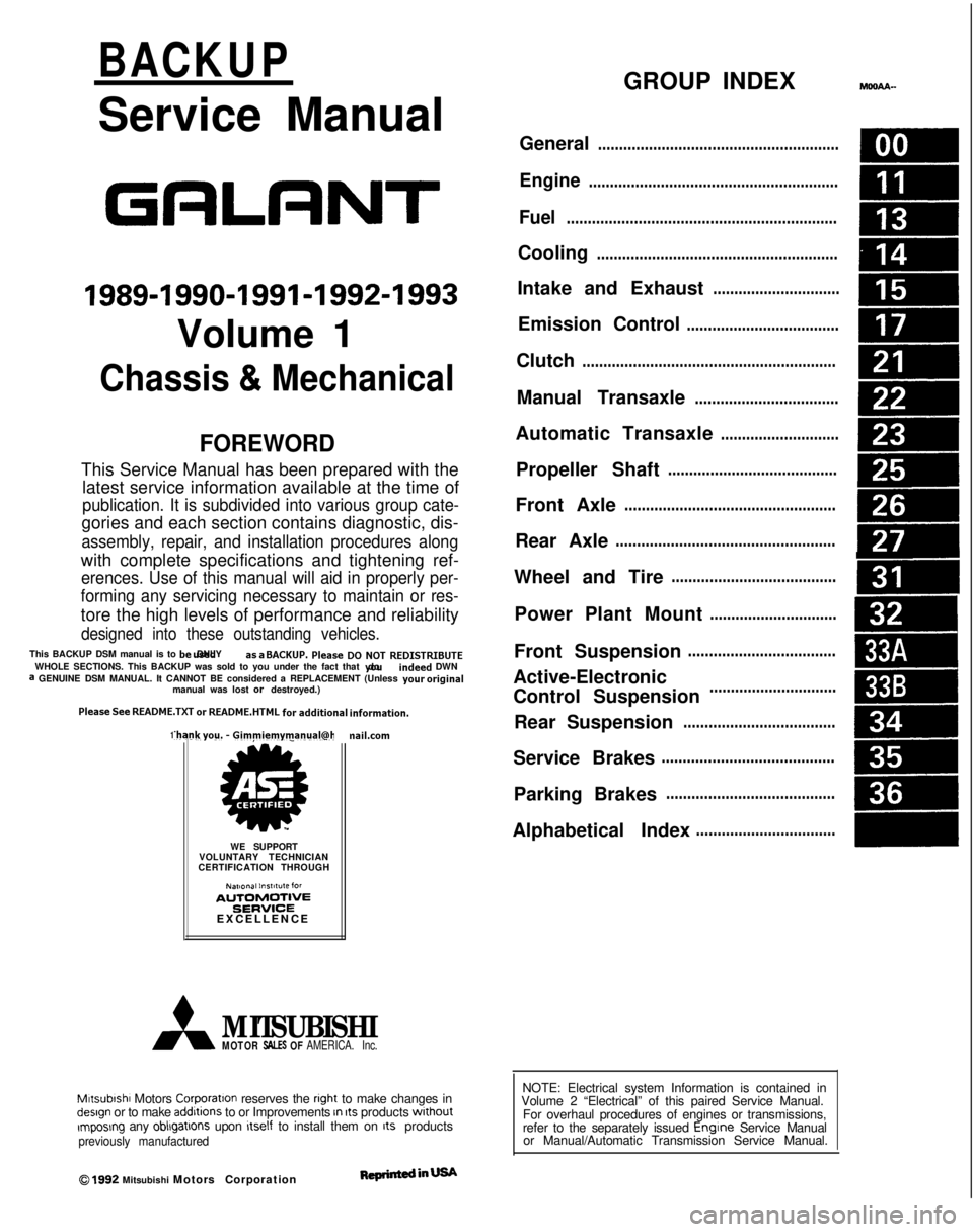
BACKUP
Service Manual
GRLRNT
1989-1990-1991-1992-1993
Volume 1
Chassis & Mechanical
FOREWORD
This Service Manual has been prepared with thelatest service information available at the time of
publication. It is subdivided into various group cate-
gories and each section contains diagnostic, dis-
assembly, repair, and installation procedures along
with complete specifications and tightening ref-
erences. Use of this manual will aid in properly per-
forming any servicing necessary to maintain or res-
tore the high levels of performance and reliability
designed into these outstanding vehicles.
This BACKUP DSM manual is to be used DNLY as
a SACKUP. please DIJ NOT REDISTRIBUTEWHOLE SECTIONS. This BACKUP was sold to you under the fact that you do indeed
DWNa GENUINE DSM MANUAL. It CANNOT BE considered a REPLACEMENT (Unless your
original
manual was lost or
destroyed.) Please
See
README.TXT
or
README.HTML
for additional
information.
1kyou.
- Gjmpiemym_ay&?h
@
A
.
.”
WE SUPPORT
VOLUNTARY TECHNICIAN
CERTIFICATION THROUGH
Nallonal lnsrltule forAU~~~v3~;VPCT:VE
EXCELLENCE naiLcorn
MITSUBISHIMOTOR SALES OF AMERICA. Inc.
Mltsublshl Motors Corporat!on reserves the right to make changes indesign or to make additions to or Improvements In Its products
wlthout~mposng any obllgatlons upon Itself to install them on its productspreviously manufactured
0 1992 Mitsubishi Motors CorporationRcprintedinUSA
GROUP INDEXMOOAA-
General.........................................................
Engine...........................................................
Fuel................................................................
Cooling.........................................................
Intake and Exhaust..............................
Emission Control....................................
Clutch............................................................
Manual Transaxle..................................
Automatic Transaxle............................
Propeller Shaft........................................
Front Axle..................................................
Rear Axle....................................................
Wheel and Tire.......................................
Power Plant Mount..............................
Front Suspension...................................
Active-Electronic
Control Suspension..............................m
A
Rear Suspension....................................&
Service Brakes.........................................
Parking Brakes........................................
Alphabetical Index.................................
NOTE: Electrical system Information is contained in
Volume 2 “Electrical” of this paired Service Manual.
For overhaul procedures of engines or transmissions,
refer to the separately issued Engine
Service Manual
or Manual/Automatic Transmission Service Manual.
Page 33 of 1273
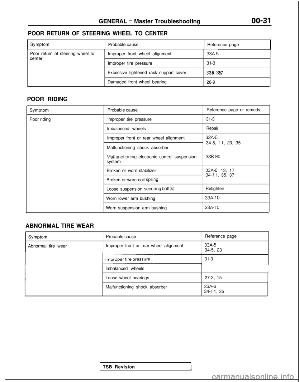
GENERAL - Master Troubleshooting
00-31
POOR RETURN OF STEERING WHEEL TO CENTER
Symptom
Probable cause Reference page
’Poor return of steering wheel to
Improper front wheel alignment33A-5center
Improper tire pressure31-3
Excessive tightened rack support cover 37A-35, 36, 37
Damaged front wheel bearing
26-9
POOR RIDING
Symptom
Poor riding Probable cause
Reference page or remedy
Improper tire pressure
31-3
lmbalanced wheelsRepair
Improper front or rear wheel alignment33A-5
34-5, 11, 23, 35
Malfunctioning shock absorber Malfunctioning
electronic control suspension
33B-90system
Broken or worn stabilizer
33A-6. 13, 1734-l 1, 35, 37
Broken or worn coil spri#ng
Loose suspension secuiring bolt(s)
Retighten
Worn lower arm bushing
33A-10
Worn suspension arm bushing 33A-IO
TSB Revision
ABNORMAL TIRE WEAR
Symptom
Abnormal tire wear Probable cause
Improper front or rear wheel alignment Reference page
33A-534-5, 23
131-3
lmbalanced wheelsII
Loose wheel bearings
27-3, 15
Malfunctioning shock absorber
33A-634-l 1, 35
Page 550 of 1273
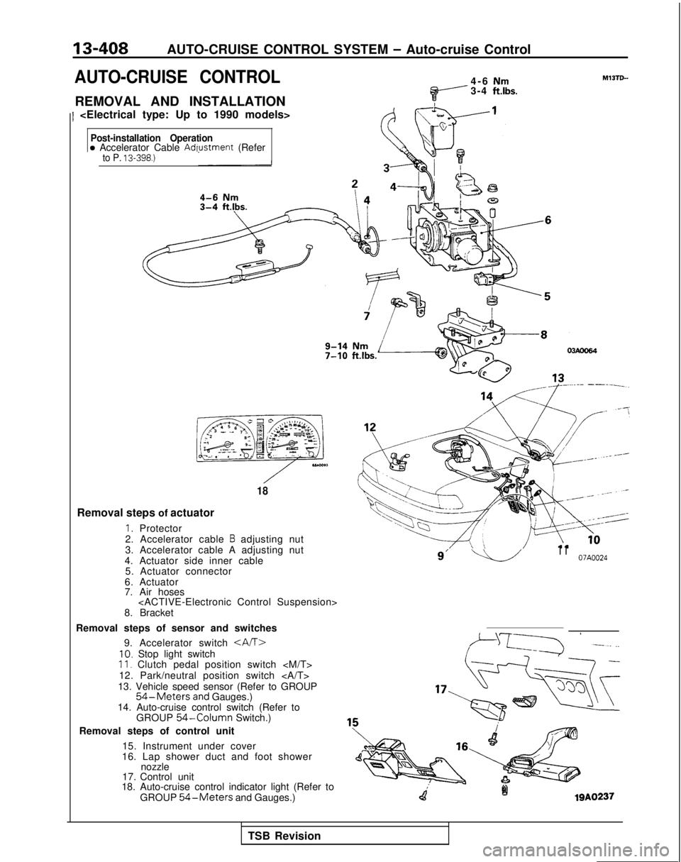
13-408AUTO-CRUISE CONTROL SYSTEM - Auto-cruise Control
AUTO-CRUISE CONTROL
REMOVAL AND INSTALLATION
1
Nm3-4 ft.lbs.
Post-installation Operationa Accelerator Cable Adwstment (Referto P. 13-398.)
,**.“qy “y ,,,,ezls:’ 3 -. .- ,*%L’J
01
,\@&&,
-<28- E+c- - - --.c,
T
$$y= *g i ;g+j$T
-3
18
Removal steps of actuator
1. Protector
2. Accelerator cable B adjusting nut
3. Accelerator cable A adjusting nut
4. Actuator side inner cable 5. Actuator connector
6. Actuator
7. Air hoses
8. Bracket
Removal steps of sensor and switches 9. Accelerator switch
10. Stop light switch11. Clutch pedal position switch
12. Park/neutral position switch
13. Vehicle speed sensor (Refer to GROUP
54-Met&sand Gauges.)
14. Auto-cruise control switch (Refer to GROUP
54-Column Switch.)
Removal steps of control unit
15. Instrument under cover
16. Lap shower duct and foot shower nozzle
17. Control unit
18. Auto-cruise control indicator light (Refer to
GROUP
54-Meters and Gauges.)
9’ -L.-lI I07A0024
falQA0237
TSB Revision
Page 588 of 1273
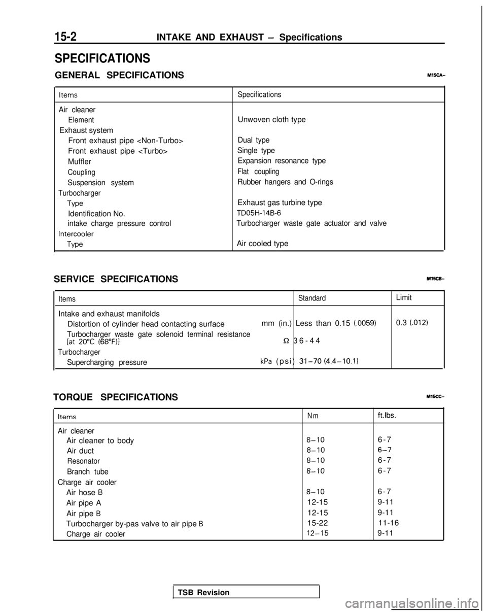
15-2INTAKE AND EXHAUST - Specifications
SPECIFICATIONS
GENERAL SPECIFICATIONSMEch-
Items
Air cleaner
Element
Exhaust systemFront exhaust pipe
Front exhaust pipe
Muffler
Coupling
Suspension system
Turbocharger
Type
Identification No.
intake charge pressure control
Intercooler
Type Specifications
Unwoven cloth type
Dual type
Single type Expansion resonance type
Flat coupling
Rubber hangers and O-rings
Exhaust gas turbine type
TD05H-14B-6
Turbocharger waste gate actuator and valve
Air cooled type
SERVICE SPECIFICATIONS
Items
Intake and exhaust manifolds
StandardLimit
Distortion of cylinder head contacting surface mm (in.) Less than 0.15 (0059)0.3 (.012)
Turbocharger waste gate solenoid terminal resistance[at 20°C (68”F)l5-2 36-4
4
Turbocharger
Supercharging pressurekPa (psi) 31-70 (4.4-10.1)
TORQUE SPECIFICATIONS
Items
Air cleaner
Air cleaner to body
Air duct
Resonator
Branch tube
Charge air cooler
Air hose B
Air pipe A Air pipe
B
Turbocharger by-pas valve to air pipe B
Charge air cooler
Nmft.lbs.
8-106-
7
8-106-7
8-106-
7
8-106-
7
8-106-
7
12-15 9-11
12-15 9-11
15-22 11-16 12-15
9-11
TSB Revision
Page 940 of 1273
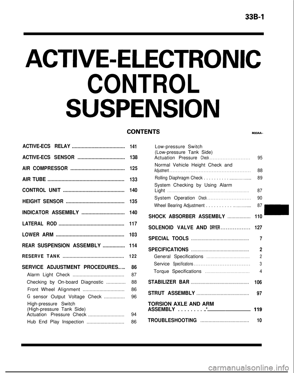
339-l
ACTIVE-ELECTRONIC
CONTROL
SUSPENSION
ACTIVE-ECS RELAY......................................141
ACTIVE-ECSSENSOR.................................. 138
AIRCOMPRESSOR.......................................125
AIR TUBE.......................................................133
CONTROLUNIT............................................ 140
HEIGHT SENSOR ..........................................
135
INDICATORASSEMBLY............................... 140
LATERALROD...............................................117
LOWER
ARM.................................................103
REAR
SUSPENSION ASSEMBLY................114
RESERVETANK............................................ 122
SERVICE ADJUSTMENT PROCEDURES.....86
Alarm Light Check.....................................87
Checking by On-board Diagnostic ..............88
FrontWheelAlignment .............................. 86
G sensor Output Voltage Check ...............96
High-pressure Switch
(High-pressure Tank Side)
Actuation Pressure Check
.......................... 94
Hub End Play Inspection ...........................86 M33AA-
Low-pressure Switch
(Low-pressure Tank Side)
Actuation
PressureCheck . . . . . . . . . . . . . . . . . . . . . . . . .95
Normal Vehicle Height Check and
Adjustment . . . . . . . . . . . . . . . . . . . . . . . . . . . . . . .\
. . . . . . . . . . . . . . . . . . .88
Rolling Diaphragm Check . . . . . . . . . . .._.............. 89
System Checking by Using Alarm
Light
. . . . . . . . . . . . . . . . . . . . . . . . . . . . . . . . . . . . \
. . . . . . . . . . . . . . . . . . . . . . . .87
System OperationCheck . . . . . . . . . . . . . . . . . . . . . . . . . . .90
Wheel Bearing Adjustment . . . . . . . . . .
.._........... 87
SHOCKABSORBER ASSEMBLY. . . . . . . . . . . . . . . . .110
SOLENOIDVALVEANDDRYER . . . . . . . . . . . . . . . . .127
SPECIAL TOOLS. . . . . . . . . . . . . . . . . . . . . . . . . . . . . . . . . . . . \
. . . . . . .7
SPECIFICATIONS. . . . . . . . . . . . . . . . . . . . . . . . . . . . . . . . . . . . \
. . . . . . .2
GeneralSpecifications. . . . . . . . . . . . . . . . . . . . . . . . . . . . . . . .2
ServiceSpecifications . . . . . . . . . . . . . . . . . . . . . . . . . . . . .\
. . . .3
TorqueSpecifications. . . . . . . . . . . . . . . . . . . . . . . . . . . . . . . . .4
STABILIZER BAR. . . . . . . . . . . . . . . . . . . . . . . . . . . . . . . . . . . . \
. . . . . . .106
STRUT ASSEMBLY. . . . . . . . . . . . . . . . . . . . . . . . . . . . . . . . . . . . \
. . .97
TORSION AXLE AND ARM
ASSEMBLY. . . . . . . . ..*.........................................119,
TROUBLESHOOTING. . . . . . . . . . . . . . . . . . . . . . . . . . . . . . . . . . . .10
Page 942 of 1273
ACTIVE-ELECTRONIC CONTROL SUSPENSION - Specifications33B-3
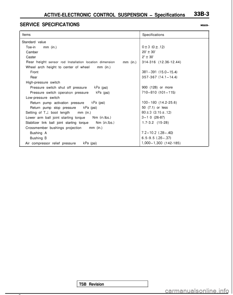
SERVICE SPECIFICATIONSM33cE-
ItemsSpecifications
Standard value Toe-in mm (in.)
O&3 (O-t.12)
Camber 20’ t 30’
Caster
2” t 30’
Rear height sensor rod Installation location dimension
mm (in.)314-316 (12.36-12.44)
Wheel arch height to center of wheel mm (in.)
Front
381-391 (15.0-15.4)
Rear357-367 (14.1-14.4)
High-pressure switch
Pressure switch shut off pressure
kPa (psi) 900 (128) or more
Pressure switch operatton
pressure
kPa (psi)710-810 (101-115)
Low-pressure switch
Return pump activation pressure
kPa (psi)100-180 (14.2-25.6)
Return pump stop pressure
kPa (psi) 50 (7.1) or less
Setting of
T.J. boot length mm (in.)80+3 (3.152.12)
Lower arm ball joint starting torque Nm (inlbs.)3-l 0 (26-87)
Stabilizer link ball joint starting torque Nm (in.lbs.)
1.7-3.2 (15-28)
Crossmember bushings projection mm (in.)
Bushing A
7.2-10.2 (.28-.40)
Bushing B6.5-9.5 (.26-.37)
Air compressor relief pressurekPa (psi) l,OOO-1,300
(142-185)
TSB Revision
Page 943 of 1273
33B-4ACTIVE-ELECTRONIC CONTROL SUSPENSION - Specifications
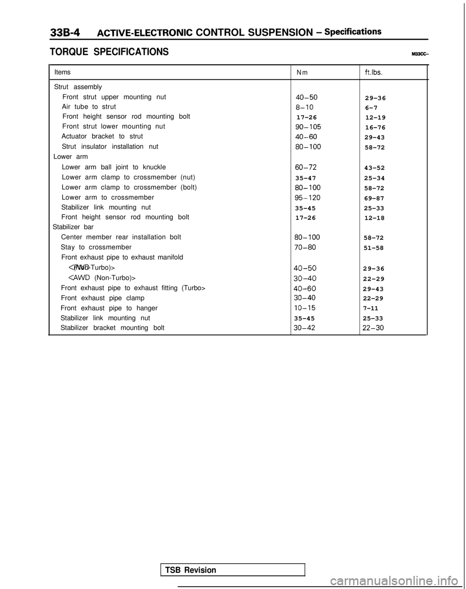
TORQUE SPECIFICATIONS
Items
Strut assembly Front strut upper mounting nut
Air tube to strut Front height sensor rod mounting bolt
Front strut lower mounting nut
Actuator bracket to strut
Strut insulator installation nut
Lower arm
Lower arm ball joint to knuckle
Lower arm clamp to crossmember (nut)
Lower arm clamp to crossmember (bolt)
Lower arm to crossmember
Stabilizer link mounting nut
Front height sensor rod mounting bolt
Stabilizer bar
Center member rear installation bolt
Stay to crossmember Front exhaust pipe to exhaust manifold
Front exhaust pipe to exhaust fitting (Turbo>
Front exhaust pipe clamp
Front exhaust pipe to hanger
Stabilizer link mounting nut
Stabilizer bracket mounting boltNmftlbs.
40-5029-36
8-106-7
17-26 12-19 go-105
16-76
40-6029-43 80-100
58-72 60-72
43-52
35-47 25-34 80-100
58-72 95-120
69-87
35-45 25-33
17-26 12-18 80-100
58-72 70-80
51-58
40-5029-36
30-4022-29
40-6029-43 30-40
22-29 IO-15
7-11
35-45
25-33 30-42 22-30
TSB Revision
Page 944 of 1273
ACTIVE-ELECTRONIC CONTROL SUSPENSION - Specifications33B-5
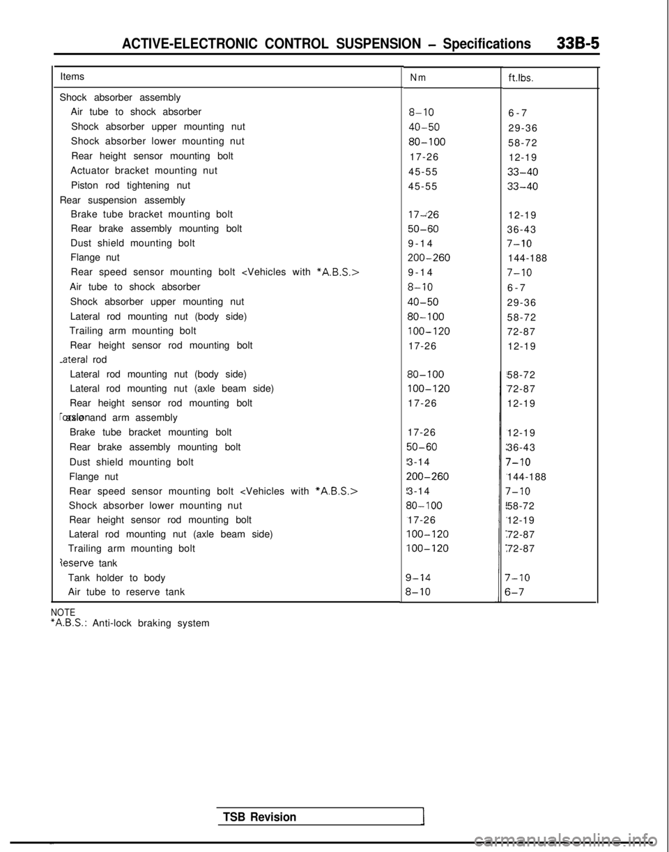
ItemsNmft.lbs.
Shock absorber assemblyAir tube to shock absorber
Shock absorber upper mounting nut
Shock absorber lower mounting nut
Rear height sensor mounting bolt
Actuator bracket mounting nut
Piston rod tightening nut
Rear suspension assembly Brake tube bracket mounting bolt
Rear brake assembly mounting bolt
Dust shield mounting bolt
Flange nut
8-106-
7
40-5029-36
80-10058-72
17-26 12-19
45-55
33-40
45-5533-40
Rear speed sensor mounting bolt
Air tube to shock absorber
Shock absorber upper mounting nut
Lateral rod mounting nut (body side)
Trailing arm mounting bolt
Rear height sensor rod mounting bolt -ateral
rod 17~26
12-19
50-6036-43
9-1
4
7-10
200-260144-188
9-1
4
7-10
8-106-
7
40-5029-36
80-10058-72
100-12072-87
17-26 12-19
Lateral rod mounting nut (body side)
Lateral rod mounting nut (axle beam side)
Rear height sensor rod mounting bolt rorsion axle and arm assembly
Brake tube bracket mounting bolt
Rear brake assembly mounting bolt
Dust shield mounting bolt
Flange nut
80-100
100-120
17-26 58-72
72-87
12-19
Rear speed sensor mounting bolt
Shock absorber lower mounting nut Rear height sensor rod mounting bolt
Lateral rod mounting nut (axle beam side)
Trailing arm mounting bolt
deserve tank 17-26
50-60
3-14
200-260
3-14
30- 100
17-26
100-120
100-120
12-19
36-43
7-10
144-188
7-10
58-72
12-19
72-87
72-87
Tank holder to body
Air tube to reserve tank
7-10
s-7
TSB Revision
NOTE “A.B.S.:
Anti-lock braking system
Page 945 of 1273
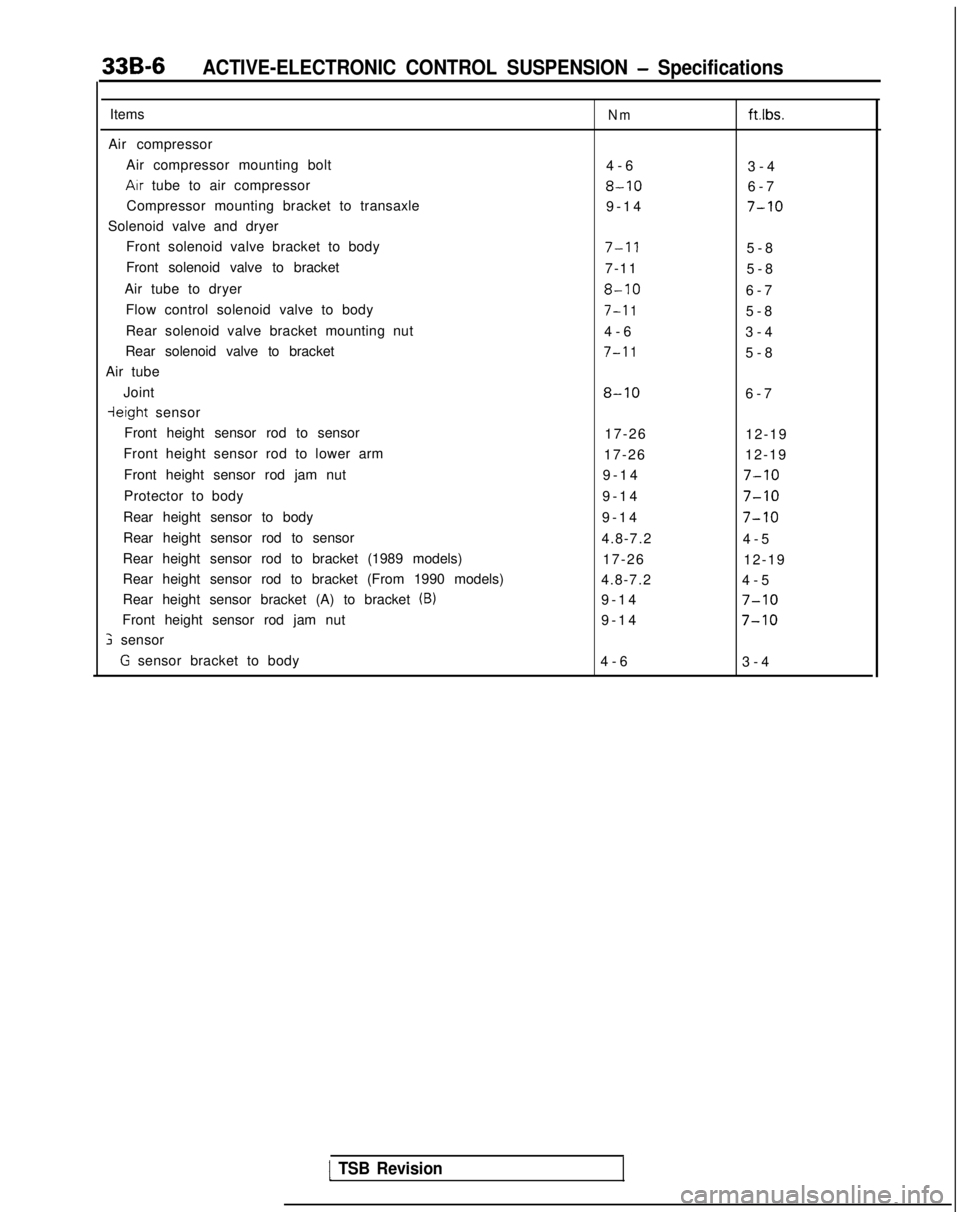
33B-6ACTIVE-ELECTRONIC CONTROL SUSPENSION - Specifications
Items
Air compressor Air compressor mounting bolt
Arr tube to air compressor
Compressor mounting bracket to transaxle
Solenoid valve and dryer Front solenoid valve bracket to body
Front solenoid valve to bracket
Air tube to dryer Flow control solenoid valve to body
Rear solenoid valve bracket mounting nut
Rear solenoid valve to bracket
Air tube
Joint
ieight sensor
Front height sensor rod to sensor
Front height sensor rod to lower arm
Front height sensor rod jam nut
Protector to body
Rear height sensor to body
Rear height sensor rod to sensor
Rear height sensor rod to bracket (1989 models)
Rear height sensor rod to bracket (From 1990 models)
Rear height sensor bracket (A) to bracket
(B)
Front height sensor rod jam nut
; sensor
G sensor bracket to body
Nmftlbs.
4-
6
3-4
8-106-
7
9-14
7-10
7-l 15-
8
7-11 5-8
8-106-
7
7-l 15-
8
4-6 3-4
7-l 15-
8
8-106-
7
17-26 12-19
17-26 12-19
9-14
7-10
9-1
4
7-10
9-1
4
7-10
4.8-7.2
4-
5
17-26 12-19
4.8-7.2 4-5
9-14
7-10
9-1
4
7-10
4-
6
3-4
1 TSB Revision
Page 950 of 1273
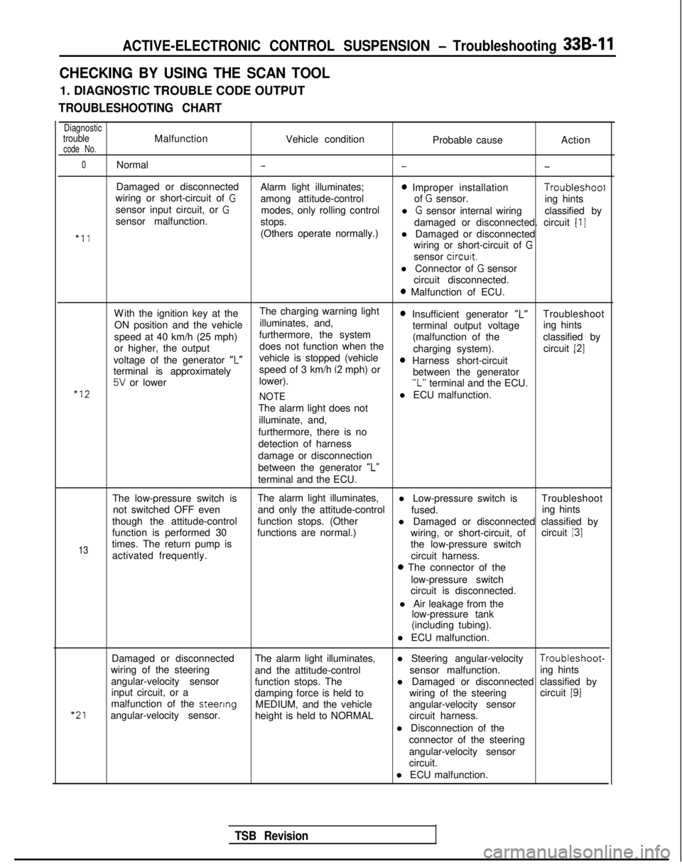
ACTIVE-ELECTRONIC CONTROL SUSPENSION - Troubleshooting 33B-11
CHECKING BY USING THE SCAN TOOL
1. DIAGNOSTIC TROUBLE CODE OUTPUT
TROUBLESHOOTING CHART
DiagnostictroubleMalfunctionVehicle conditioncode No.Probable causeAction
0Normal---
Damaged or disconnected
Alarm light illuminates;0 Improper installation Troubleshoof
wiring or short-circuit of Gamong attitude-control of G sensor.
sensor input circuit, or Ging hints
modes, only rolling control
sensor malfunction. l
G sensor internal wiring
classified by
stops. damaged or disconnected. circuit
[I]
“11(Others operate normally.)l Damaged or disconnected
wiring or short-circuit of
G
sensor circurt.
l Connector of
G sensor
circuit disconnected.
0 Malfunction of ECU.
W
ith the ignition key at the
The charging warning light
ON position and the vehicle illuminates, and,
0 Insufficient generator “L”Troubleshoot
speed at 40 km/h (25 mph) furthermore, the system terminal output voltage
ing hints
or higher, the output does not function when the (malfunction of the
classified by
charging system). circuit
[2]
voltage of the generator ‘I”vehicle is stopped (vehicle0 Harness short-circuit
terminal is approximately speed of 3 km/h (2 mph) or
5V or lower
lower). between the generator“L” terminal and the ECU.“12
NOTEl ECU malfunction.
The alarm light does not illuminate, and,
furthermore, there is no
detection of harness
damage or disconnection
between the generator “L”
terminal and the ECU.
The low-pressure switch is The alarm light illuminates,
l Low-pressure switch is Troubleshoot
not switched OFF even and only the attitude-control
fused.
though the attitude-control ing hints
function stops. (Other l Damaged or disconnected classified by
function is performed 30 functions are normal.) circuit
131
13times. The return pump is wiring, or short-circuit, of
the low-pressure switch
activated frequently. circuit harness.
0 The connector of the
low-pressure switch
circuit is disconnected.
l Air leakage from the low-pressure tank
(including tubing).
l ECU malfunction.
“21
Damaged or disconnected The alarm light illuminates,l Steering angular-velocity Troubleshoot-
wiring of the steering and the attitude-control sensor malfunction.
angular-velocity sensor ing hints
function stops. The
input circuit, or a l Damaged or disconnected classified by
damping force is held to wiring of the steeringcircuit
191malfunction of the steenng
MEDIUM, and the vehicle
angular-velocity sensor. angular-velocity sensor
height is held to NORMAL circuit harness.
l Disconnection of the connector of the steering
angular-velocity sensor
circuit.
l ECU malfunction.
TSB Revision