brake pads MITSUBISHI GALANT 1989 Service Repair Manual
[x] Cancel search | Manufacturer: MITSUBISHI, Model Year: 1989, Model line: GALANT, Model: MITSUBISHI GALANT 1989Pages: 1273, PDF Size: 37.62 MB
Page 3 of 1273

00-l
GENERAL
CONTENTS
GENERAL DATA AND SPECIFICATIONS.....23
HOWTOUSETHISMANUAL......................
3
Definition of Terms ......................................3
ExplanationofCircuitDiagrams..................7
Explanation of
ManualContents .................4
Explanation of the Troubleshooting
Guide .............................................................
6
Model
Indications .........................................3
Scope of Maintenance, Repair and
Servicing Explanations
..................................
3
Troubleshooting .............................................3
LUBRICATIONANDMAINTENANCE............
34
MAINTENANCE SERVICE............................... 39
AirCleanerElement
.....................................39
Automatic
Transaxle
.....................................43
Ball Joint and Steering Linkage Seals ........45
Brake Hoses................................................. 45
Disc Brake Pads ........................................... 44
Drive Belt (For Water Pump and
Generator) .......................................................
41
Drive
Shaft Boots .........................................45
Engine Coolant
............................................. 44
Engine Oil .....................................................
41
Engine Oil Filter ...........................................41
Exhaust System
............................................ 45
FuelHoses
...................................................39
Fuel System
.................................................39
Manual Transaxle ..........................................42
RearAxle......................................................45
Rear Drum Brake Linings and
RearWheel Cylinders
..................................44
Spark
Plugs...................................................40
Timing Belt...................................................40
MASTER
TROUBLESHOOTING.....................28
PRECAUTIONS
BEFORESERVICE................15
RECOMMENDED LUBRICANTS AND
LUBRICANT CAPACITIESTABLE..................35
SCHEDULED
MAINTENANCETABLE ...........38
SPECIAL HANDLING INSTRUCTIONS
FOR AWD MODELS
.......................................20
TABLE OF MAIN SEALANTS
AND
ADHESIVES ............................................46
TIGHTENING TORQUE
................................... 27
TOWING
ANDHOISTING ..............................17
VEHICLE
IDENTIFICATION .............................8
Chassis Number ...........................................
11
EngineModel
Stamping
...............................12
Theft Protection ............................................12
Vehicle Identification Code Chart Plate.......
8
Vehicle Identification Number List
..............8
Vehicle Identification Number Location .......
8
Vehicle Information
CodePlate...................1 1
Vehicle SafetyCertificationLabel................12
Page 40 of 1273
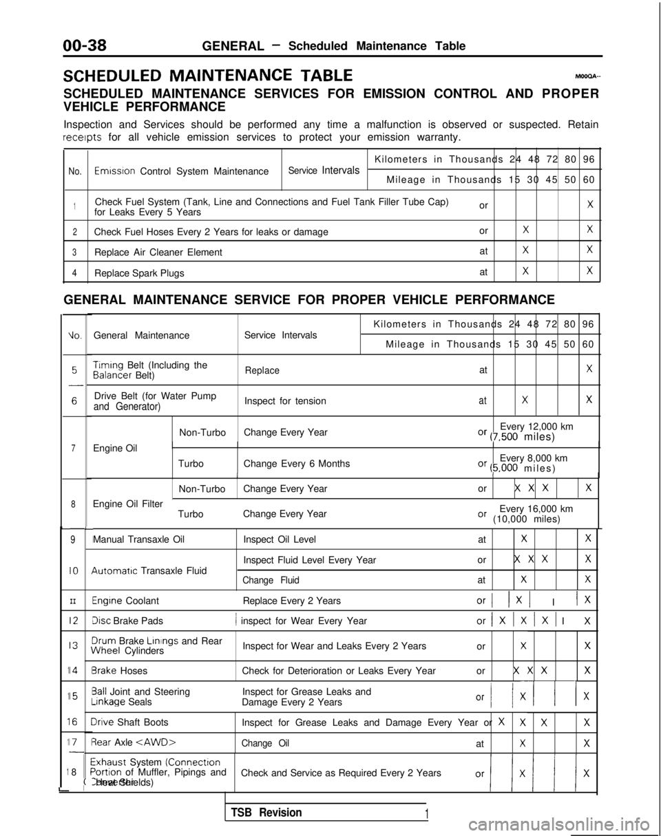
00-38GENERAL- Scheduled Maintenance Table
SCHEDULED MAINTENANCE
TABLEMOOOA-
SCHEDULED MAINTENANCE SERVICES FOR EMISSION CONTROL AND PROPER
VEHICLE PERFORMANCE
Inspection and Services should be performed any time a malfunction is ob\
served or suspected. Retain receipts
for all vehicle emission services to protect your emission warranty.
Kilometers in Thousands 24 48 72 80 96
No.Emwsron Control System MaintenanceService IntervalsMileage in Thousands 15 30 45 50 60
1Check Fuel System (Tank, Line and Connections and Fuel Tank Filler Tube\
Cap) orXfor Leaks Every 5 Years
2Check Fuel Hoses Every 2 Years for leaks or damage orXX
3Replace Air Cleaner ElementatXX
4Replace Spark PlugsatXX
GENERAL MAINTENANCE SERVICE FOR PROPER VEHICLE PERFORMANCE
L
1
1
1
1
1
i
IO.General Maintenance
Service Intervals
7Engine Oil
8
9
IO
III2
I3
14
15
I6
I71
8
L
I
I
I
I
I\
I
II
I
I
;(
Kilometers in Thousands 24 48 72 80 96
Mileage in Thousands 15 30 45 50 60 Timing
Belt (Including the Balancer
Belt)
ReplaceatX
Drive Belt (for Water Pump
Inspect for tensionatXXand Generator)
Non-TurboChange Every Year Every 12,000 kmOr (7,500 miles)
Turbo Change Every 6 Months Every 8,000 km
Or (5.000 miles
)
II
Non-Turbo
Change Every Year or X X XX
Every 16,000 kmOr (10,000 miles)
Engine Oil Filter
TurboChange Every Year
Manual Transaxle Oil 4utomatrc
Transaxle Fluid Inspect Oil Level
at
XX
Inspect Fluid Level Every Yearor X X XX
Change FluidatXX
Engine Coolant
Replace Every 2 YearsOrI 1x1 I IX
Disc Brake Pads1 inspect for Wear Every Yearor/XlXlXl I
X
3rum
Brake Linings
and Rear iNheel
Cylinders Inspect for Wear and Leaks Every 2 Years
or
XX
3rake HosesCheck for Deterioration or Leaks Every Year or X X XX
3all Joint and SteeringInspect for Grease Leaks and-inkage
Seals
Damage Every 2 Years
Or I/ XII x
Irive Shaft Boots Inspect for Grease Leaks and Damage Every Year or XXXX
3ear Axle
Exhaust System (Connectron>ortion of Muffler, Pipings and
Check and Service as Required Every 2 YearsConverter Heat Shields)
TSB Revision1
Page 46 of 1273
GENERAL -Maintenance Service
(1O)Star-t engine and allow to idle for at least two minutes.
Then, with parking brake on, move selector
fever
momentarily to each position, ending in “N” Neutral
position.
(11)Add sufficient ATF to bring fluid level to lower mark.
Recheck fluid level after transaxle is at normal Operating
temperature. Fluid level should be between upper and lower marks of
“HOT” range, Insert dipstick fully to prevent dirt from
entering transaxle.
OOA0051
11 .ENGINE
COOLANT (Change)MOOSEEAC
Check the cooling system parts, such as radiator, heater,
and oil cooler hoses, thermostat and connections for
leakage and damage.
CHANGE COOLANT
1. Remove the radiator cap.
2. Loosen the drain plug to drain the coolant.
3. Drain the coolant from the reserve tank.
4. After draining the coolant, tighten the drain plug securely.
5.Supply the coolant into the radiator until it is filled up to
its filler neck.
6. Supply the coolant into the reserve tank.
7. After warming the engine until the thermostat opens, remove the radiator cap and check the coolant level.
8.Supply the coolant into the radiator until it is filled up to
its filler neck, and install the radiator cap securely.
9.Fill the reserve tank with coolant up to the “FULL” line.
14K512
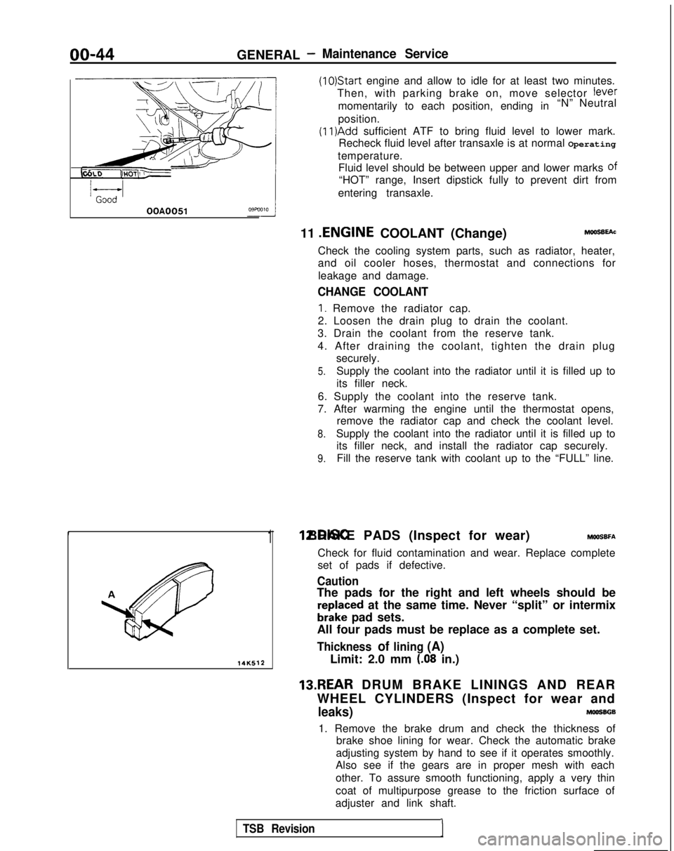
1 12.DISC BRAKE PADS (Inspect for wear) MWSBFA
Check for fluid contamination and wear. Replace complete
set of pads if defective.
Caution
The pads for the right and left wheels should be
reDlaced at the same time. Never “split” or intermix
brkke pad sets.
All four pads must be replace as a complete set.
Thickness of lining (A)
Limit: 2.0 mm (.08 in.)
13.REAR DRUM BRAKE LININGS AND REAR
WHEEL CYLINDERS (Inspect for wear and
leaks)MOOSBGB
1. Remove the brake drum and check the thickness of brake shoe lining for wear. Check the automatic brake
adjusting system by hand to see if it operates smoothly.
Also see if the gears are in proper mesh with each
other. To assure smooth functioning, apply a very thin
coat of multipurpose grease to the friction surface of
adjuster and link shaft.
TSB Revision1
Page 1135 of 1273
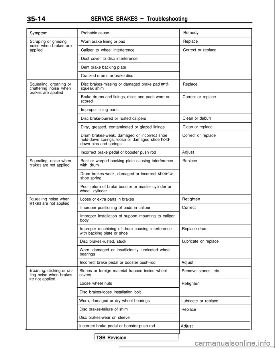
35-14SERVICE BRAKES - Troubleshooting
Symptom
Scraping or grinding
noise when brakes are
applied Probable cause
Worn brake lining or pad
Caliper to wheel interference
Dust cover to disc interference Remedy
Replace
Correct or replace
Bent brake backing plate
Cracked drums or brake disc
Squealing, groaning or
chattering noise when
brakes are applied Disc brakes-missing or damaged brake pad anti-
squeak shim Replace
Brake drums and linings, discs and pads worn or
scored Correct or replace
Improper lining parts
Disc brake-burred or rusted calipers
Dirty, greased, contaminated or glazed linings
Drum brakes-weak, damaged or incorrect shoe
hold-down springs, loose or damaged shoe hold-
down pins and springs Clean or deburr
Clean or replace
Correct or replace
Squealing. noise when ,rakes
are not applied Incorrect brake pedal or booster push rod
Bent or warped backing plate causing interference
with drum
Drum brakes-weak, damaged or incorrect shoe-to-
shoe spring Adjust
Replace
jquealing noise when Irakes
are not applied Poor return of brake booster or master cylinder or
wheel cylinder
Loose or extra parts in brakes Retighten
Improper positioning of pads in caliper
Improper installation of support mounting to caliper
body Correct
Improper machining of drum causing interference
with backing plate or shoe
Disc brakes-rusted, stuck
Worn, damaged or insufficiently lubricated wheel bearings Replace drum
Lubricate or replace
Incorrect brake pedal or booster push-rod Adjust
sroaning. clicking or rat-Stones or foreign material trapped inside wheel
Remove stones, etc.
ling noise when brakes covers
Ire not applied
Loose wheel nuts Retighten
Disc brakes-loose installation bolt
Worn, damaged or dry wheel bearings Disc brakes-failure of shim
Disc brakes-wear on sleeve Lubricate or replace
Replace
Incorrect brake pedal or booster push-rod Adjust
1 TSB Revision
Page 1180 of 1273
SERVICE BRAKES - Service Adjustment Procedures35-59
14 LO169
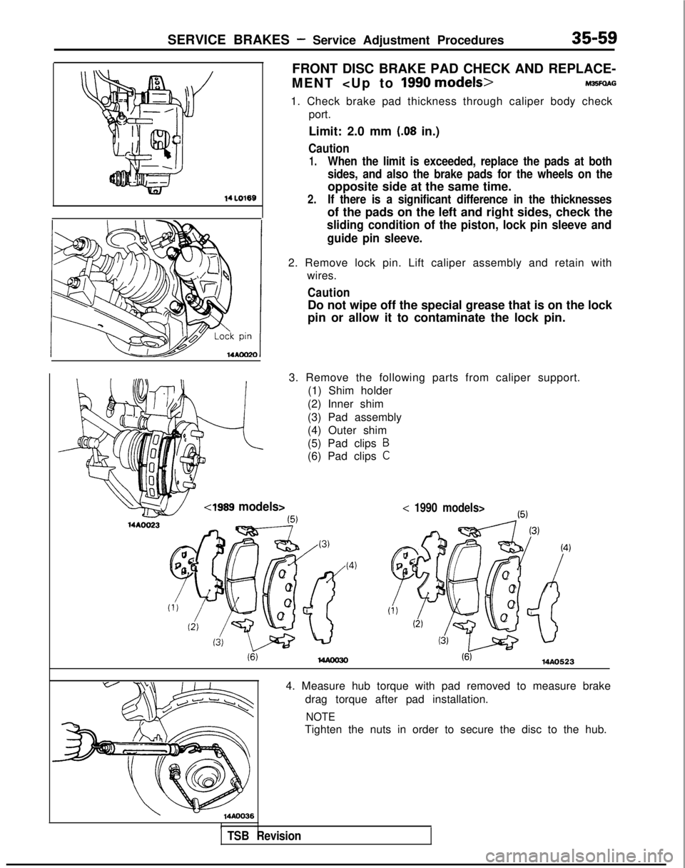
FRONT DISC BRAKE PAD CHECK AND REPLACE-
MENT
1. Check brake pad thickness through caliper body check port.
Limit: 2.0 mm
(.08 in.)
Caution
1.When the limit is exceeded, replace the pads at both
sides, and also the brake pads for the wheels on the
opposite side at the same time.
2.If there is a significant difference in the thicknesses
of the pads on the left and right sides, check the
sliding condition of the piston, lock pin sleeve and
guide pin sleeve.
2. Remove lock pin. Lift caliper assembly and retain with wires.
Caution
Do not wipe off the special grease that is on the lock
pin or allow it to contaminate the lock pin.
3. Remove the following parts from caliper support. (1) Shim holder
(2) Inner shim
(3) Pad assembly
(4) Outer shim
(5) Pad clips
B
(6) Pad clips C
Cl989 models>< 1990 models>
(6)MAO523
14AOO361
4. Measure hub torque with pad removed to measure brake drag torque after pad installation.
NOTE
Tighten the nuts in order to secure the disc to the hub.
TSB Revision
Page 1181 of 1273

35-60SERVICE BRAKES - Service Adjustment Procedures
Pad assembly
\
l4RO367
IWhen newWhen wornI
PadWea 5. Securely attach the pad clip to the caliper support.
6. Apply a coating of the specified grease to the pad, shim
and shim holder installation surfaces, and then install the
shim and shim holder.
Apply the grease so that the grease doesn’t ooze out from
the edges.
Specified grease: Brake grease SAE 5310,
NLGI No. 1
Caution
Do not deposit grease or other dirt on pad or brake disc
friction surfaces.
7.Be careful that the piston boot does not become caught,
when lowering the caliper assembly and install the lock pin.
8. Check brake drag torque as follows.
(1) Start engine and hold brake pedal down for 5 seconds.
(2) Stop engine.
(3) Turn brake disc forward IO times.
(4) Check brake drag torque with spring scale.
If the difference between brake drag torque and hub
torque exceeds the standard value, disassemble piston and clean the piston. Check for corrosion or worn piston
seal, and check the sliding condition of the lock pin sleeve
and guide pin sleeve.
Standard value: 70
N (15.4 Ibs.) or less
[4 Nm (3 ftlbs.)]
or less
FRONT DISC BRAKE PAD CHECK AND
REPLACEMENT
NOTE
The brake pads have been equipped with wear indicators, so
that when the brake pad thickness reached 2 mm
(.08 in.), the
wear indicator touches the brake discs and produces a warning
squeaking sound.
Brake disc
Page 1182 of 1273
SERVICE BRAKES - Service Adjustment Procedures35-61
ICM-R44V, M-R46V>
MAO563
14AOO23
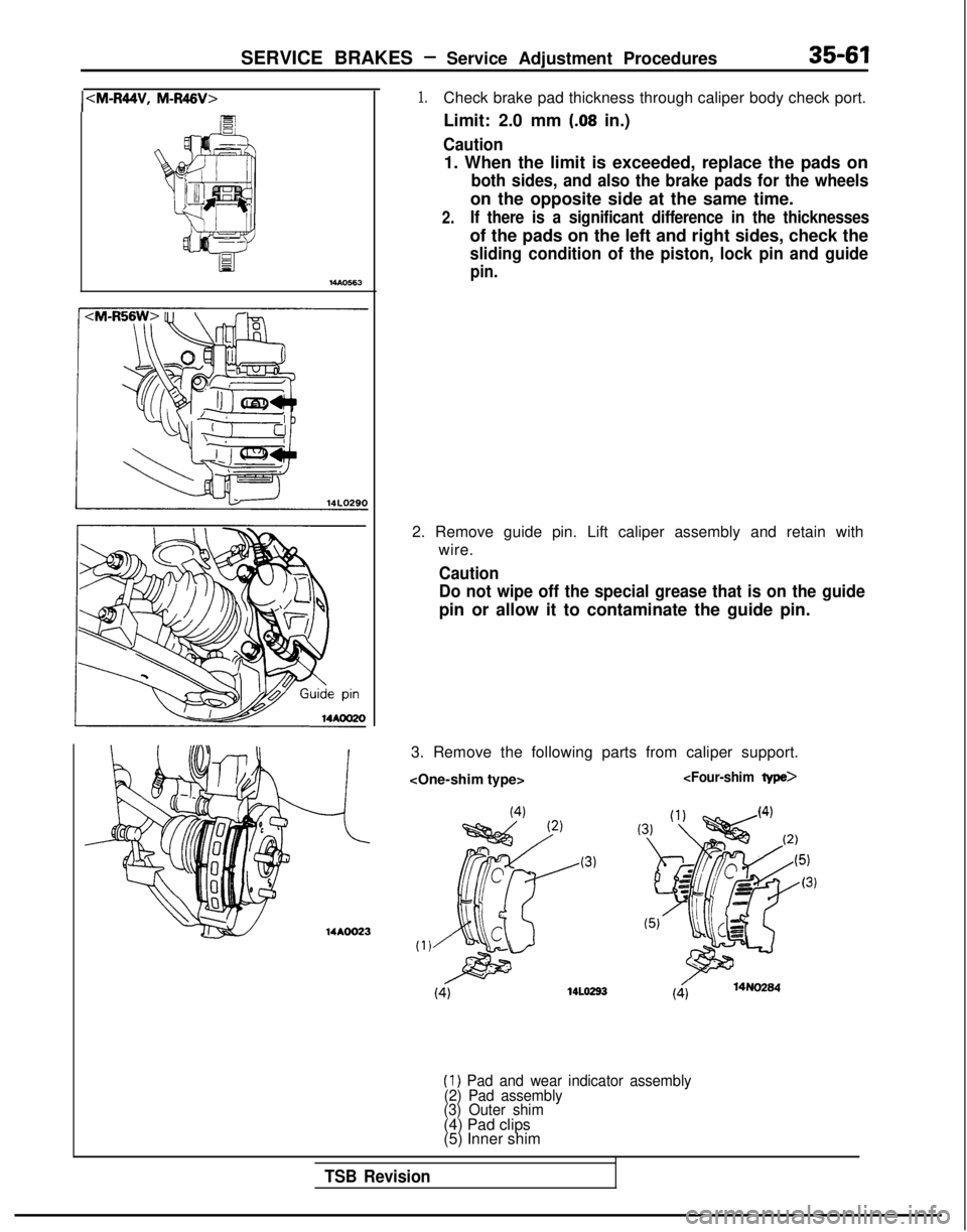
1.Check brake pad thickness through caliper body check port.
Limit: 2.0 mm
(.08 in.)
Caution
1. When the limit is exceeded, replace the pads on
both sides, and also the brake pads for the wheels
on the opposite side at the same time.
2.If there is a significant difference in the thicknesses
of the pads on the left and right sides, check the
sliding condition of the piston, lock pin and guide
pin.
2. Remove guide pin. Lift caliper assembly and retain with
wire.
Caution
Do not wipe off the special grease that is on the guide
pin or allow it to contaminate the guide pin.
3. Remove the following parts from caliper support.
14Lo293(414N0284
(1) Pad and wear indicator assembly
(2) Pad assembly
(3) Outer shim
(4) Pad clips
(5) Inner shim
TSB Revision
Page 1183 of 1273
35-62SERVICE BRAKES - Service Adjustment Procedures
u /@$fi 14A0Ol5CM-R56W>
II
I
Pad
c
4s14FOO97
!m
!
bly
c
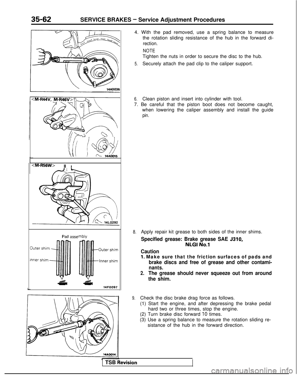
4. With the pad removed, use a spring balance to measure
the rotation sliding resistance of the hub in the forward di-
rection.
NOTE
Tighten the nuts in order to secure the disc to the hub.
5.Securely attach the pad clip to the caliper support.
6.Clean piston and insert into cylinder with tool.
7. Be careful that the piston boot does not become caught, when lowering the caliper assembly and install the guide
pin.
8.Apply repair kit grease to both sides of the inner shims.
Specified grease: Brake grease SAE 5310,
NLGI No.1
Caution
1. Make sure that the friction surfaces of pads and
brake discs and free of grease and other contami-
nants.
2.The grease should never squeeze out from around
the shim.
9.Check the disc brake drag force as follows.
(1) Start the engine, and after depressing the brake pedal hard two or three times, stop the engine.
(2) Turn brake disc forward
10 times.
(3) Use a spring balance to measure the rotation sliding re- sistance of the hub in the forward direction.
TSB
hevision
Page 1186 of 1273
SERVICE BRAKES - Service Adjustment Procedures35-65’
14AO281
WA0204
grooves
Q
0 0
Projection
1410037I-
REAR DISC BRAKE PAD CHECK AND
REPLACEMENT
MBBFUAE
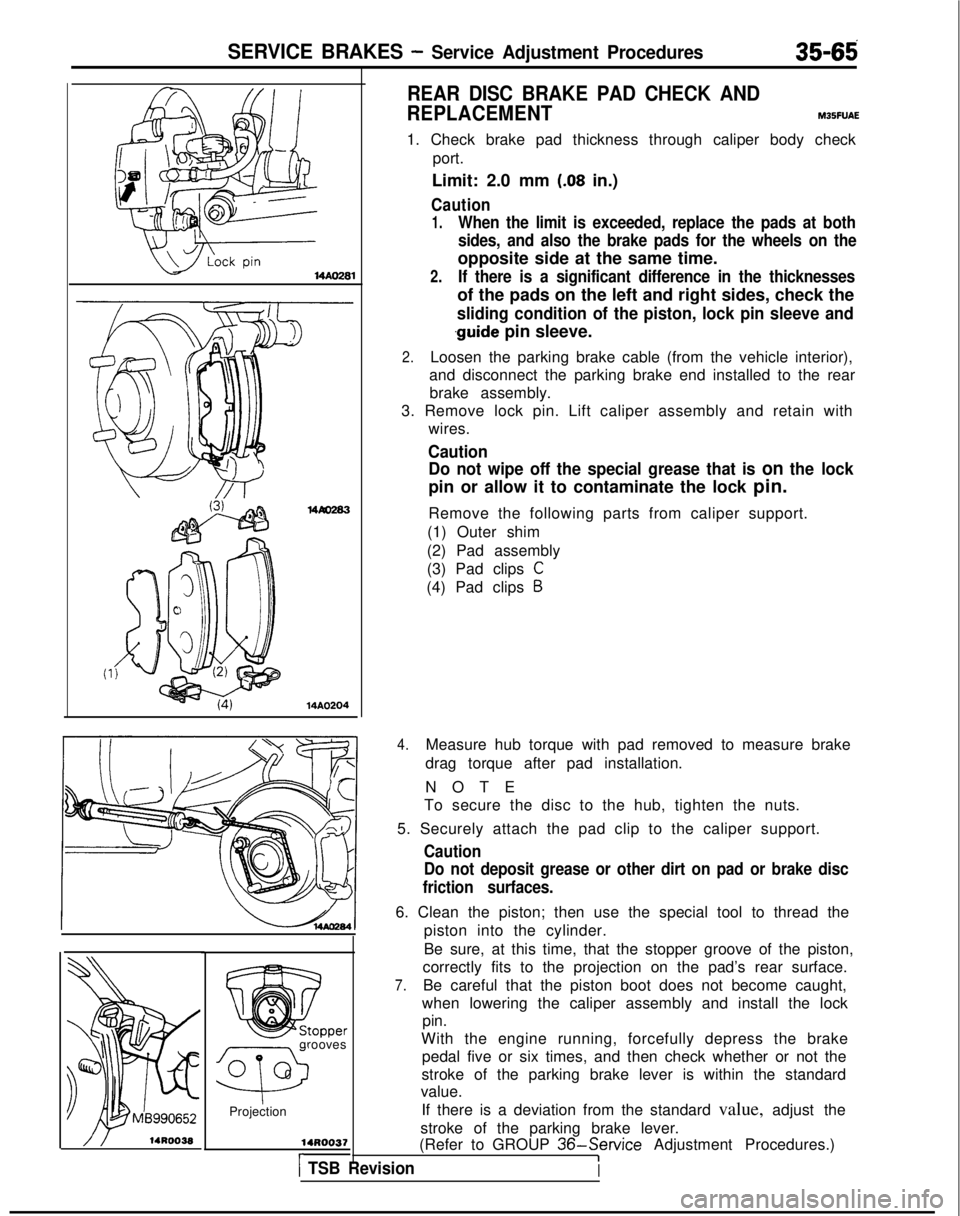
1. Check brake pad thickness through caliper body check port.
Limit: 2.0 mm
(.08 in.)
Caution
1.When the limit is exceeded, replace the pads at both
sides, and also the brake pads for the wheels on the
opposite side at the same time.
2.If there is a significant difference in the thicknesses
of the pads on the left and right sides, check the
sliding condition of the piston, lock pin sleeve and
.guide pin sleeve.
2.Loosen the parking brake cable (from the vehicle interior),
and disconnect the parking brake end installed to the rear brake assembly.
3. Remove lock pin. Lift caliper assembly and retain with wires.
CautionDo not wipe off the special grease that is
on the lock
pin or allow it to contaminate the lock pin.
Remove the following parts from caliper support.
(1) Outer shim
(2) Pad assembly
(3) Pad clips
C
(4) Pad clips B
4.Measure hub torque with pad removed to measure brake
drag torque after pad installation.
NOT
E
To secure the disc to the hub, tighten the nuts.
5. Securely attach the pad clip to the caliper support.
Caution
Do not deposit grease or other dirt on pad or brake disc
friction surfaces.
6. Clean the piston; then use the special tool to thread the piston into the cylinder.
Be sure, at this time, that the stopper groove of the piston,
correctly fits to the projection on the pad’s rear surface.
7.Be careful that the piston boot does not become caught,
when lowering the caliper assembly and install the lock pin.
With the engine running, forcefully depress the brake pedal five or six times, and then check whether or not the
stroke of the parking brake lever is within the standard
value.
If there is a deviation from the standard value, adjust the
stroke of the parking brake lever.
(Refer to GROUP
36-Service Adjustment Procedures.)I) TSB RevisionI
Page 1257 of 1273
36-2PARKING BRAKES - Specifications/Troubleshooting/Service Adjustment Procedures
SPECIFICATIONS
GENERAL SPECIFICATIONS
ItemsSpecifications
TypeMechanical brake acting on rear wheels
Parking brake lever typeLever type
Cable arrangementV-type
SERVICE SPECIFICATION
Items
Standard value
Parking brake lever stroke Specifications5-7 notches
TROUBLESHOOTING
Symptom
Probable cause Remedy
Poor parking brake
function +Worn brake pad Poor condition of brake pad surface Replace
Parking brake cable sticking
Auto-adjuster malfunction Adjust
Excessive parking brake lever stroke
Adjust the parking brake lever
stroke or check the parking
brake cable arrangement
I
i
!14A023C
SERVICE ADJUSTMENT PROCEDURES
PARKING BRAKE LEVER STROKE CHECKM~~FEAJ
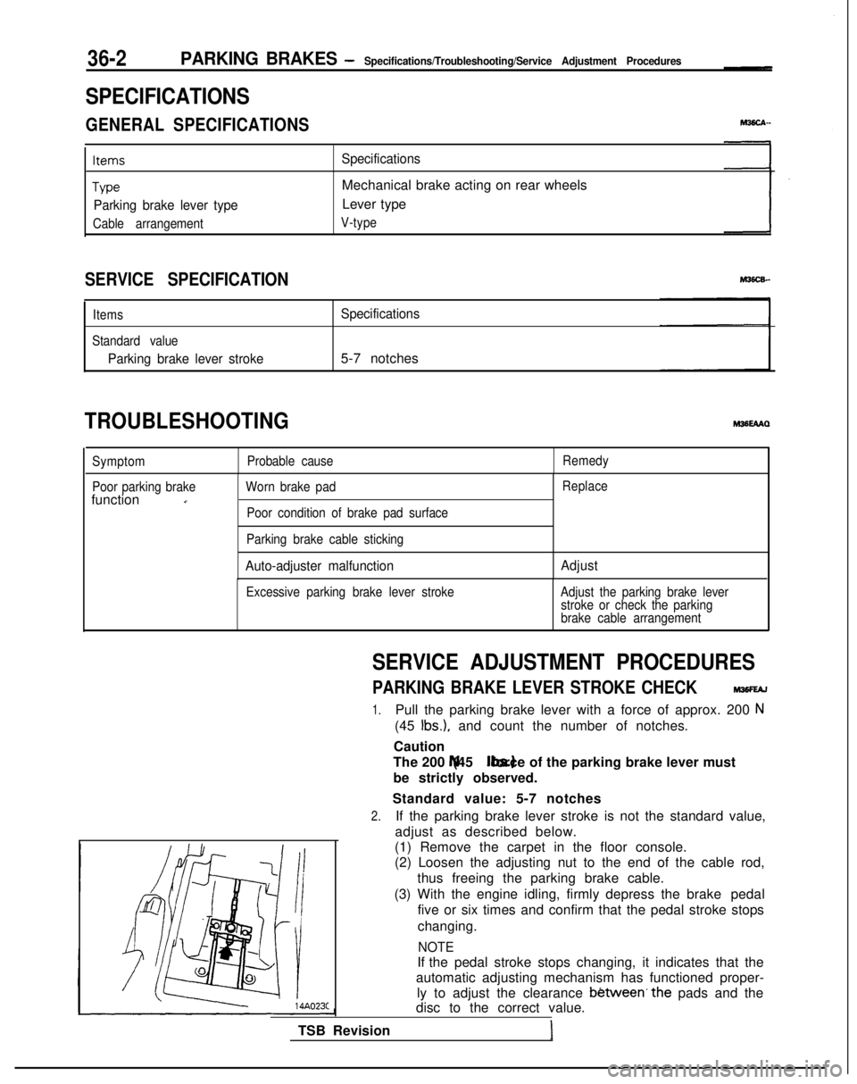
1.Pull the parking brake lever with a force of approx. 200 N
(45 Ibs.), and count the number of notches.
Caution
The 200 N (45 Ibs.) force of the parking brake lever must
be strictly observed.
Standard value: 5-7 notches
2.If the parking brake lever stroke is not the standard value,
adjust as described below.
(1) Remove the carpet in the floor console.
(2) Loosen the adjusting nut to the end of the cable rod,
thus freeing the parking brake cable.
(3) With the engine idling, firmly depress the brake pedal
five or six times and confirm that the pedal stroke stops
changing.
NOTE
If the pedal stroke stops changing, it indicates that the
automatic adjusting mechanism has functioned proper- ly to adjust the clearance
b&ween’the pads and the
disc to the correct value.
TSB Revision