dead battery MITSUBISHI GALANT 1989 Service Repair Manual
[x] Cancel search | Manufacturer: MITSUBISHI, Model Year: 1989, Model line: GALANT, Model: MITSUBISHI GALANT 1989Pages: 1273, PDF Size: 37.62 MB
Page 58 of 1273

II-8ENGINE
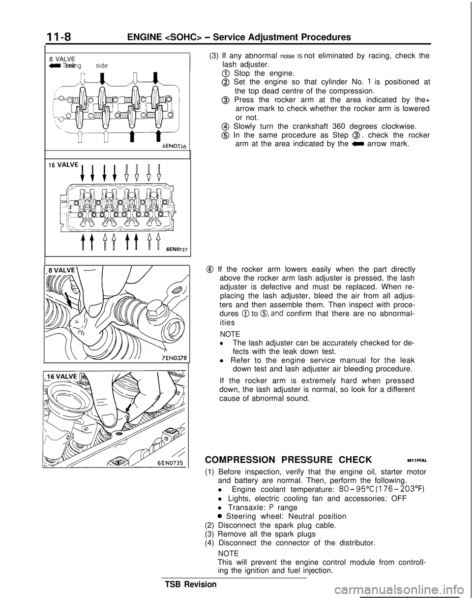
8 VALVE
W Tlmlng belt side
il6
16
727
(3) If any abnormal noise IS not eliminated by racing, check the
lash adjuster.
@ Stop the engine.
@ Set the engine so that cylinder No. 1 is positioned at
the top dead centre of the compression.
@ Press the rocker arm at the area indicated by the+ arrow mark to check whether the rocker arm is lowered
or not.
@ Slowly turn the crankshaft 360 degrees clockwise.
@ In the same procedure as Step 0, check the rocker
arm at the area indicated by the
0 arrow mark.
@ If the rocker arm lowers easily when the part directly
above the rocker arm lash adjuster is pressed, the lash
adjuster is defective and must be replaced. When re-
placing the lash adjuster, bleed the air from all adjus-
ters and then assemble them. Then inspect with proce-
dures
@ to 0, and confirm that there are no abnormal-
ities
NOTE
lThe lash adjuster can be accurately checked for de-
fects with the leak down test.
l Refer to the engine service manual for the leak down test and lash adjuster air bleeding procedure.
If the rocker arm is extremely hard when pressed
down, the lash adjuster is normal, so look for a different
cause of abnormal sound.
COMPRESSION PRESSURE CHECK
MllFFAL
(1) Before inspection, verify that the engine oil, starter motor and battery are normal. Then, perform the following.
l Engine coolant temperature:
80- 95°C
(176- 203°F)
l Lights, electric cooling fan and accessories: OFF
l Transaxle:
P range
0 Steering wheel: Neutral position
(2) Disconnect the spark plug cable.
(3) Remove all the spark plugs
(4) Disconnect the connector of the distributor.
NOTE
This will prevent the engine control module from controll- ing the ignition and fuel injection.
TSB Revision
Page 158 of 1273

13-16
FUEL SYSTEM
FAILSAFE/BACK-UP FUNCTIONS LIST
If trouble with any major sensor is detected by the on-board diagnostic,\
the vehicle will be kept in the safe
driving conditions according to the preset control logic.
Trouble item Control content for trouble
Volume air flow Fuel injection timing and ignition timing are determined according to th\
e throttle position
sensor sensor
(TPS) and engine revolution speed signal (crankshaft position sensor signal)\
.
Intake air temperature The control is executed with the suction air temperature regarded as
25°C (77°F).
sensor
Throttle position The fuel injection rate is not increased for acceleration according to t\
he throttle position
sensor
(TPS)sensor signal.
Idle speed control After the idle speed control motor plunger is driven and contracted, the\
idle revolution speed
motor position sensor is not controlled.
Engine coolant The control is executed with the engine coolant temperature regarded as \
8OO.C (176°F).temperature sensor (Even if the sensor signal becomes normal again, the control is continued
until the ignltlon
switch is turned off.)
Camshaft position Simultaneous injection of fuel is executed for all cylinders. (In this \
case, the
No.1 cylinder top
sensor dead center is not detected at all after the ignition key is turned on.)\
Barometric pressure The control is executed with the pressure regarded as 760 mmHg
(30
in.Hg).
sensor
Oxygen sensor Closed loop control of the air/fuel mixture ratio is not executed.
i
READ OUT OF DIAGNOSTIC TROUBLE CODE
Precautions for operation
(1) When battery voltage is low, no detection of failure is possible. Be sure to check the battery for voltage and
other conditions before starting the test.
(2) On-board diagnostic item is erased if the battery or the engine control module connector is discon-
nected. Do not disconnect the battery before the di-
agnostic result is completely read.
Using Scan Tool
(1) Switch OFF the ignition switch.
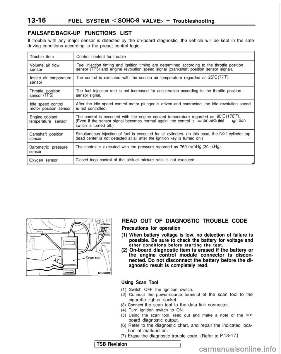
(2) Connect the power-source terminal of the scan tool to the
cigarette lighter socket.
(3) Connect the scan tool to the data link connector. (4) Turn ignition switch to ON.
(5) Using the scan tool, read out and make a note of the
on-
board diagnostic output.
(6) Refer to the diagnostic chart, and repair the indicated loca-
tion of malfunction.
(7) Erase the diagnostic trouble code. (Refer to
P.13-17.)
1 TSB RevisionI