engine overheat MITSUBISHI GALANT 1989 Service Repair Manual
[x] Cancel search | Manufacturer: MITSUBISHI, Model Year: 1989, Model line: GALANT, Model: MITSUBISHI GALANT 1989Pages: 1273, PDF Size: 37.62 MB
Page 30 of 1273
00-28GENERAL - Tightening Torque/Master Troubleshooting
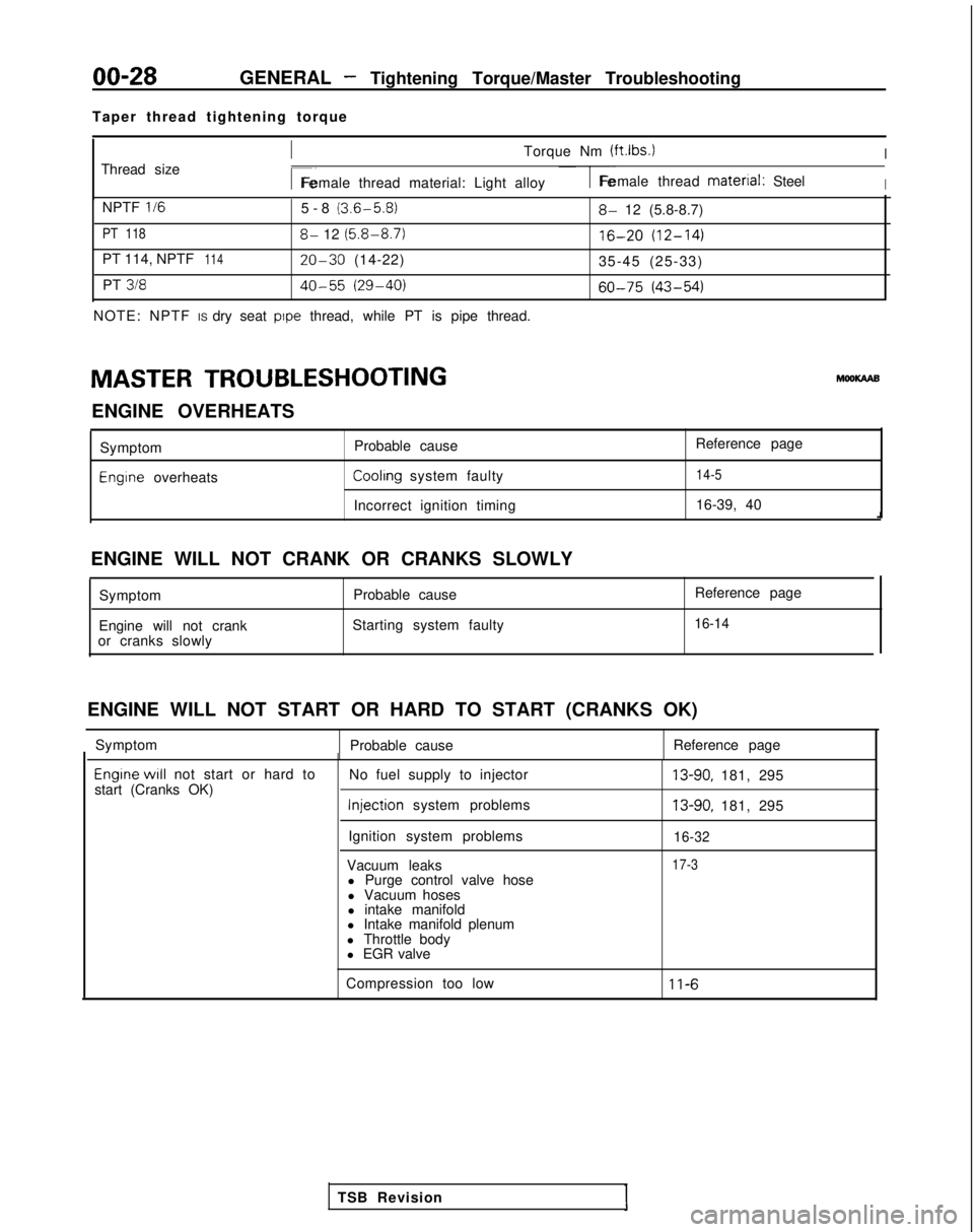
Taper thread tightening torque
Thread size
ITorque Nm (ftlbs.)I
r~Female thread material: Light alloy1-Female thread material: SteelI
NPTF II65-8 (3.6-5.8)
PT 1188- 12 (5.8-8.7)
PT 114, NPTF11420-30 (14-22)
PT
31840-55 (29-40)
NOTE: NPTF IS dry seat pope thread, while PT is pipe thread.
8- 12 (5.8-8.7)
16-20 (12-14)
35-45 (25-33)
60-75 (43-54)
MASTER TROUBLESHOOTING hlooKAAB
ENGINE OVERHEATS Symptom
Engine overheats Probable cause
Reference pageCoolrng system faulty14-5
Incorrect ignition timing
16-39, 40
ENGINE WILL NOT CRANK OR CRANKS SLOWLY Symptom Probable cause
Engine will not crank Starting system faulty
or cranks slowly Reference page
16-14
ENGINE WILL NOT START OR HARD TO START (CRANKS OK)
Symptom Probable cause Reference page
Engrne WIII not start or hard to
start (Cranks OK) No fuel supply to injector Injection
system problems
Ignition system problems
Vacuum leaks l Purge control valve hose
l Vacuum hoses
l intake manifold
l Intake manifold plenum
l Throttle body
l EGR valve13-90, 181, 295
13-90, 181, 295
16-32
17-3
Compression too low11-6
TSB Revision
Page 31 of 1273
GENERAL - Master Troubleshooting00-29
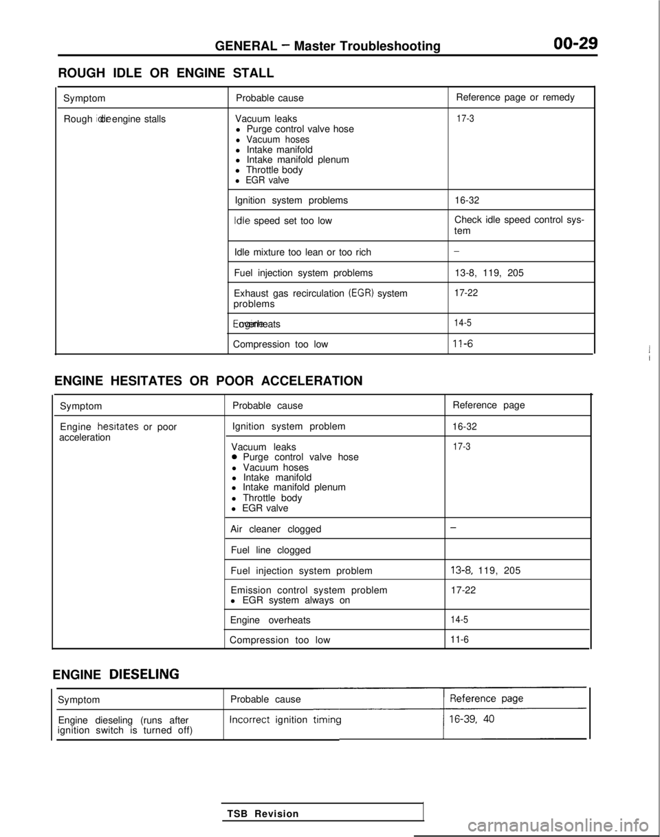
ROUGH IDLE OR ENGINE STALL
SymptomRough idle or engine stalls
Probable cause
Vacuum leaks l Purge control valve hose
l Vacuum hosesl Intake manifold
l Intake manifold plenum
l Throttle body
l EGR valve
Ignition system problems Idle
speed set too low Reference page or remedy
17-3
16-32
Check idle speed control sys-
tem
Idle mixture too lean or too rich
Fuel injection system problems
Exhaust gas recirculation
(EGR) system
problems Engine overheats
Compression too low
-
13-8, 119, 205
17-22
14-5
11-6
ENGINE HESITATES OR POOR ACCELERATION
Symptom
Engine hesrtates
or poor
acceleration Probable cause
Ignition system problem
Vacuum leaks
0 Purge control valve hose
l Vacuum hoses
l Intake manifold
l Intake manifold plenum
l Throttle body
l EGR valve Reference page
16-32
17-3
Air cleaner clogged
Fuel line clogged
Fuel injection system problem
Emission control system problem
l EGR system always on
Engine overheats
Compression too low-
13-8, 119, 205
17-22
14-5
11-6
ENGINE DIESELING
Probable cause Incorrect
ignition
timincc
TSB Revision
Symptom
Engine dieseling (runs after
ignition switch is turned off)
Page 267 of 1273
FUEL SYSTEM
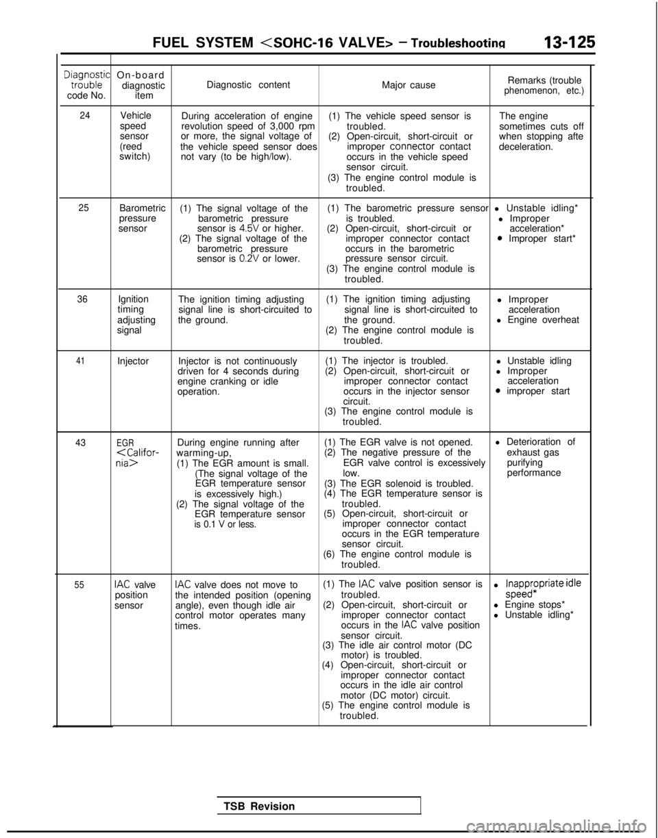
Dta,i;o;ic On-board
diagnostic
code No. item Diagnostic content
Major causeRemarks (trouble
phenomenon, etc.)
24
Vehicle
speed
sensor
(reed
switch) During acceleration of engine
(1) The vehicle speed sensor is The engine
revolution speed of 3,000 rpm troubled.sometimes cuts off
or more, the signal voltage of (2) Open-circuit, short-circuit or when stopping afte
the vehicle speed sensor does improper connector
contact
deceleration.
not vary (to be high/low). occurs in the vehicle speed
sensor circuit.
(3) The engine control module is troubled.
25Barometric (1) The signal voltage of the (1) The barometric pressure sensor l Unstable idling*
pressure barometric pressure is troubled. l Improper
sensor sensor is
4.5V or higher.(2) Open-circuit, short-circuit or acceleration*
(2) The signal voltage of the improper connector contact0 Improper start*
barometric pressure occurs in the barometric
sensor is
0.2V or lower. pressure sensor circuit.
(3) The engine control module is troubled.
36Ignition
timing
adjusting
signal The ignition timing adjusting
(1) The ignition timing adjusting
l Improper
signal line is short-circuited to signal line is short-circuited toacceleration
the ground. the ground.l Engine overheat
(2) The engine control module is troubled.
41Injector Injector is not continuously
driven for 4 seconds during
engine cranking or idle
operation. (1) The injector is troubled.
(2) Open-circuit, short-circuit or improper connector contact
occurs in the injector sensor
circuit. l Unstable idling
l Improper acceleration
0 improper start
(3) The engine control module is troubled.
43EGRDuring engine running after (1) The EGR valve is not opened. l Deterioration of
purifying
(The signal voltage of the low. performance
EGR temperature sensor (3) The EGR solenoid is troubled.
is excessively high.) (4) The EGR temperature sensor is
(2) The signal voltage of the troubled.
EGR temperature sensor (5) Open-circuit, short-circuit or
is 0.1 V or less.improper connector contact
occurs in the EGR temperature
sensor circuit.
(6) The engine control module is
troubled.
55IAC valveIAC valve does not move to (1) The IAC valve position sensor is
position the intended position (opening troubled.l ;papp$Priate idle
sensor angle), even though idle air (2) Open-circuit, short-circuit or
l Engine stops*
control motor operates many improper connector contactl Unstable idling*
times. occurs in the
IAC valve position
sensor circuit.
(3) The idle air control motor (DC
motor) is troubled.
(4) Open-circuit, short-circuit or
improper connector contact
occurs in the idle air control
motor (DC motor) circuit.
(5) The engine control module is
troubled.
TSB Revision
Page 553 of 1273
14-1
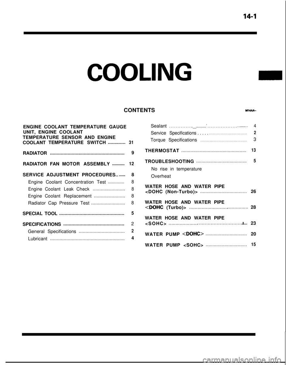
COOLING
ENGINE COOLANT TEMPERATURE GAUGE
UNIT, ENGINE COOLANT
TEMPERATURE SENSOR AND ENGINE
COOLANT TEMPERATURE
SWITCH.............
31
RADIATOR ....................................................... 9
RADIATOR FAN MOTOR ASSEMBLY ..........
12
SERVICE ADJUSTMENT PROCEDURES..
.....
8
Engine Coolant Concentration Test .............
8
Engine Coolant LeakCheck
........................8
Engine Coolant
Replacement .......................
8
Radiator Cap Pressure Test .........................
8
SPECIAL TOOL................................................5
SPECIFICATIONS .............................................
2
General Specifications ..................................
2
Lubricant
....................................................... 4
CONTENTS
IM14AA-
Sealant. . . . . . . . . . . . . ..__...........’ . . . . . . . . . . . . . \
. . . . . .._.........4
ServiceSpecifications . . . . .. . . . . . . . . . . . . . . . . . . . . . . . . . . . .2
Torque
Specifications. . . . . . . . . . . . . . . . . . . . . . . . . . . . . . . . . . .3
THERMOSTAT. . . . . . . . . . . . . . . . . . . . . . . . . . . . . . . . . . . . \
. . . . . . . . . . . . .13
TROUBLESHOOTING. . . . . . . . . . . . . . . . . . . . . . . . . . . . . . . . . . . . \
. .5
No rise in temperature
Overheat
WATER HOSE AND WATER PIPE
. . . . . . . . . . . . . . . . . . . . . . . . . . . . . . . . . . .26
WATER HOSE AND WATER PIPE
WATER HOSE AND WATER PIPE
. . . . . . . . . . . . . . . . . . . . .
. . . . . . . . . . . . . . . . . . . . . . . . . . . . . ..a.....23
WATER PUMP
WATER PUMP
. . . . . . . . . . . . . . . . . . . . . . . . . . . . . . .15
Page 557 of 1273
COOLING - Special TooVTroubleshooting
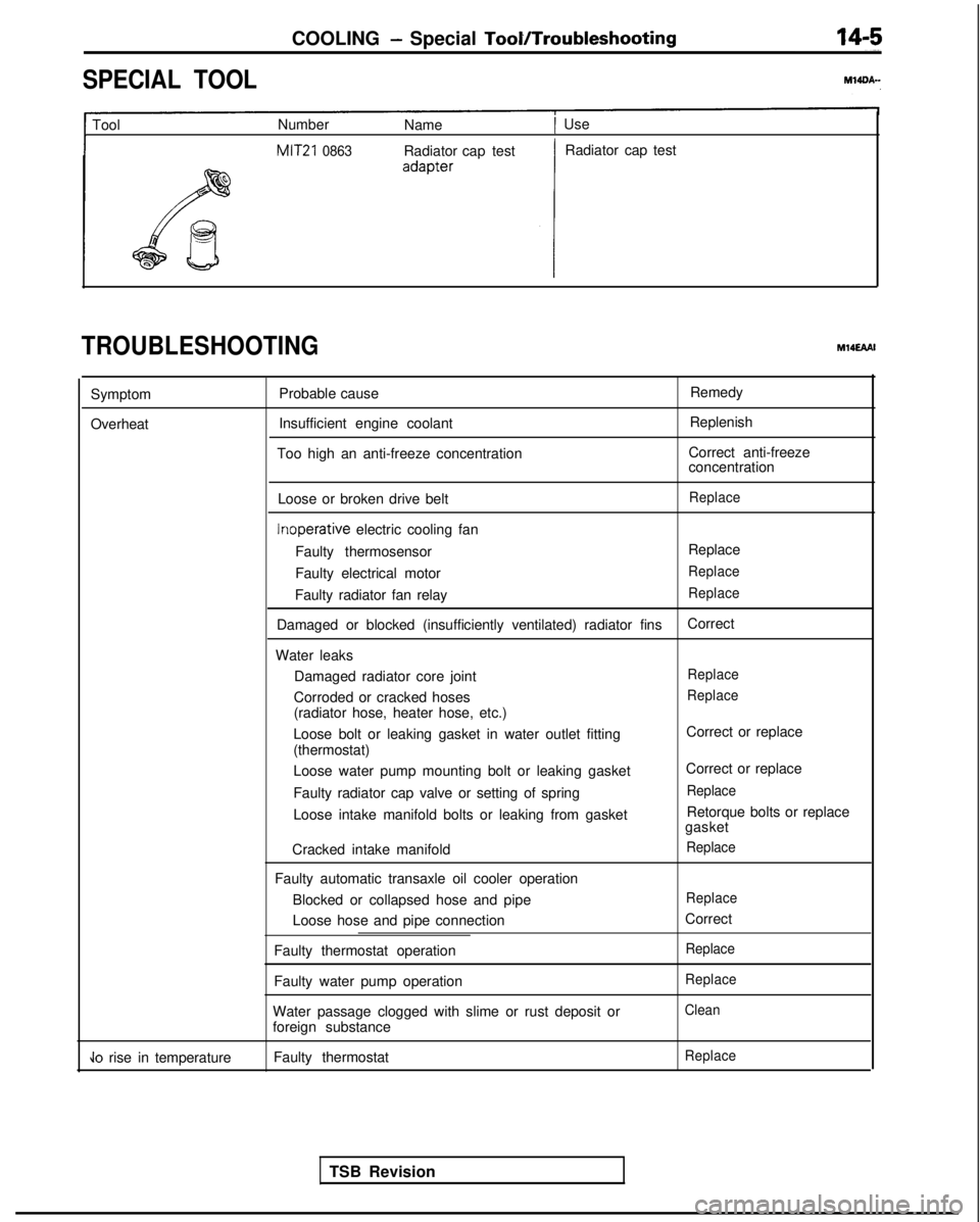
SPECIAL TOOL
1 Tool
Number
Name1 Use
MIT21 0863Radiator cap test Radiator cap test
TROUBLESHOOTINGM14EAAI
Symptom
Overheat Probable cause
Insufficient engine coolant
Too high an anti-freeze concentration Remedy
Replenish
Correct anti-freeze
concentration
Loose or broken drive belt
Replace Inoperative
electric cooling fan
Faulty thermosensor Replace
Faulty electrical motor
Replace
Faulty radiator fan relayReplace
Damaged or blocked (insufficiently ventilated) radiator fins Correct
Water leaks Damaged radiator core joint
Replace
Corroded or cracked hosesReplace
(radiator hose, heater hose, etc.)
Loose bolt or leaking gasket in water outlet fitting
(thermostat)
Loose water pump mounting bolt or leaking gasket
Faulty radiator cap valve or setting of spring
Loose intake manifold bolts or leaking from gasket
Cracked intake manifold
Faulty automatic transaxle oil cooler operation Blocked or collapsed hose and pipe
Loose hose and pipe connection
Faulty thermostat operation
Faulty water pump operation
Water passage clogged with slime or rust deposit or
foreign substance Correct or replace
Correct or replace
Replace
Retorque bolts or replace
gasket
Replace
Replace
Correct
Replace
Replace
Clean
Jo rise in temperature Faulty thermostatReplace
TSB Revision
Page 649 of 1273
I6EM0187
EMISSION CONTROL SYSTEMSExhaust Gas Recirculation (EGR) System/- Catalytic Converter/Air-fuel Ratio Control (MPI) System17-29
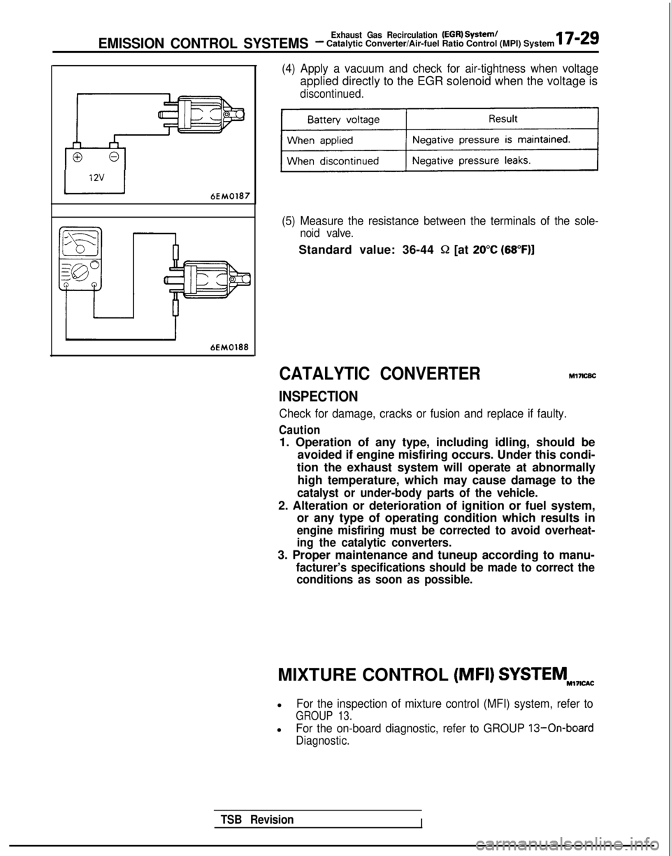
(4) Apply a vacuum and check for air-tightness when voltage
applied directly to the EGR solenoid when the voltage is
discontinued.
(5) Measure the resistance between the terminals of the sole-
noid valve.
Standard value: 36-44 Q [at 20°C (68”F)]
CATALYTIC CONVERTERMl7lcBc
INSPECTION
Check for damage, cracks or fusion and replace if faulty.
Caution
1. Operation of any type, including idling, should be
avoided if engine misfiring occurs. Under this condi-
tion the exhaust system will operate at abnormally high temperature, which may cause damage to the
catalyst or under-body parts of the vehicle.
2. Alteration or deterioration of ignition or fuel system, or any type of operating condition which results in
engine misfiring must be corrected to avoid overheat-
ing the catalytic converters.
3. Proper maintenance and tuneup according to manu-
facturer’s specifications should be made to correct theconditions as soon as possible.
TSB RevisionI
MIXTURE CONTROL (MFI) SYSTEMNI,I,w
lFor the inspection of mixture control (MFI) system, refer to
GROUP 13.
lFor the on-board diagnostic, refer to GROUP 13-On-board
Diagnostic.