turn signal MITSUBISHI GALANT 1989 Service Repair Manual
[x] Cancel search | Manufacturer: MITSUBISHI, Model Year: 1989, Model line: GALANT, Model: MITSUBISHI GALANT 1989Pages: 1273, PDF Size: 37.62 MB
Page 152 of 1273
13-10
FUEL SYSTEM
at sensor side
1\~“‘,““W,O,’ ‘\*N 4-cnDQ5a,, \llllf,,
c 3 c-11 ‘.<-!
( .[&
;%* \ g ~ &.$$~&%,;
0%: E
.Oj-,,
giI lOWI -,n
/ ~ ( ~~‘-~~~
-.mo .u. m,.0 - rj*> ;;
indicator lamp68AOO93
l
If the voltage (power-supply voltage) supplied to a sensor
is not normal, repair the harness. If the voltage to the sensor is still not normal after the har-
ness has been repaired, repalce the engine control module
and check again.
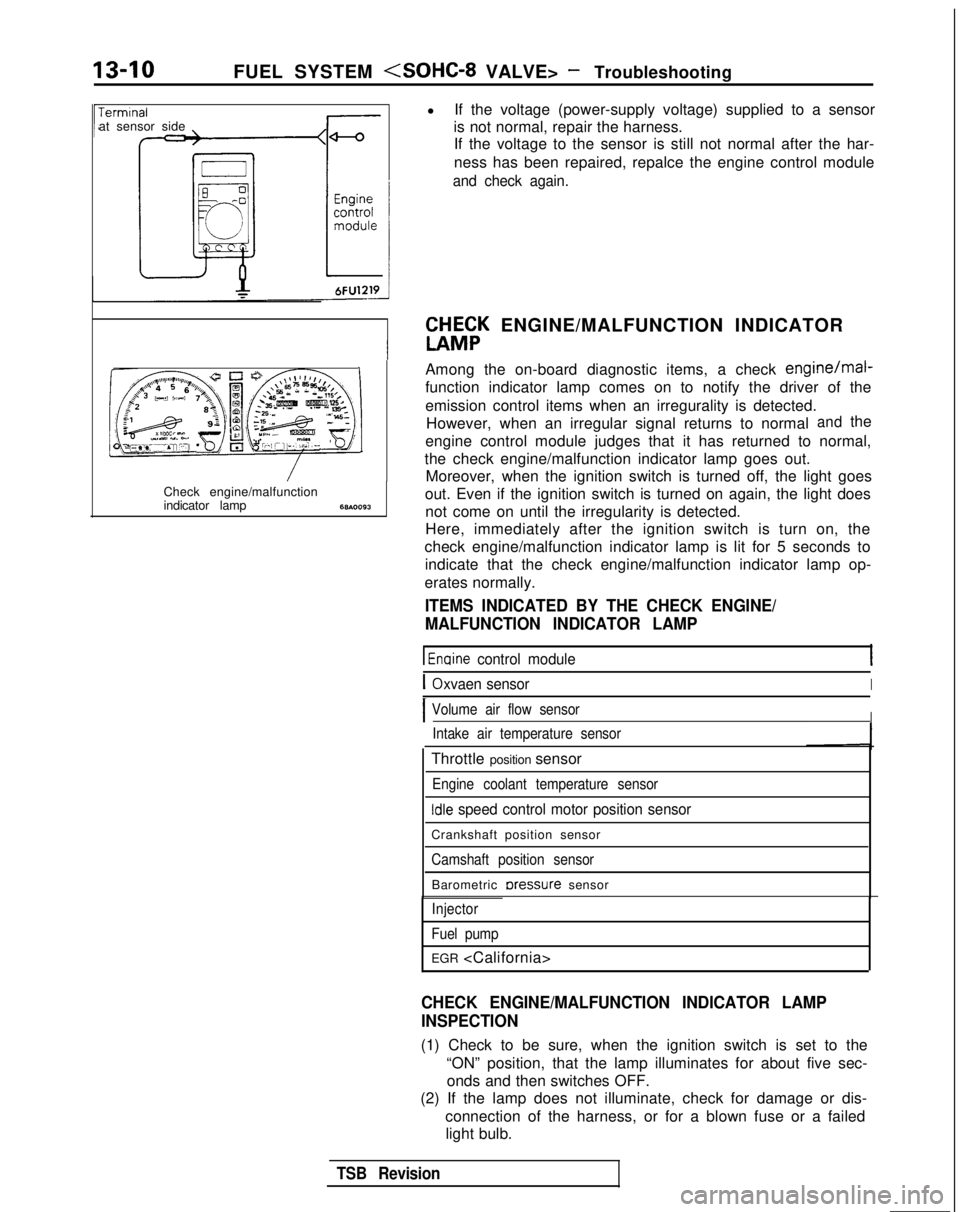
W&K ENGINE/MALFUNCTION INDICATOR
Among the on-board diagnostic items, a check
engine/mal-
function indicator lamp comes on to notify the driver of the
emission control items when an irregurality is detected. However, when an irregular signal returns to normal
andthe
engine control module judges that it has returned to normal,
the check engine/malfunction indicator lamp goes out. Moreover, when the ignition switch is turned off, the light goes
out. Even if the ignition switch is turned on again, the light does not come on until the irregularity is detected.
Here, immediately after the ignition switch is turn on, the
check engine/malfunction indicator lamp is lit for 5 seconds to indicate that the check engine/malfunction indicator lamp op-
erates normally.
ITEMS INDICATED BY THE CHECK ENGINE/
MALFUNCTION INDICATOR LAMP
1 Enaine control module
IOxvaen sensorI
IVolume air flow sensorIIntake air temperature sensor
Throttle position sensor
Engine coolant temperature sensor
Idle speed control motor position sensor
Crankshaft position sensor
Camshaft position sensor
Barometric rxessure sensor
Injector
Fuel pump
EGR
CHECK ENGINE/MALFUNCTION INDICATOR LAMP
INSPECTION
(1) Check to be sure, when the ignition switch is set to the “ON” position, that the lamp illuminates for about five sec-onds and then switches OFF.
(2) If the lamp does not illuminate, check for damage or dis-
connection of the harness, or for a blown fuse or a failedlight bulb.
TSB Revision
Page 153 of 1273
FUEL SYSTEM
ON-BOARD DIAGNOSTIC-
The engine control module monitors the input/out-
put signals (some signals at all times and the others
under specified conditions) of the engine control
module.
When it is noticed that an irregularity has continued
for a specified time or longer from when the irregu- lar signal is initially monitored, passing a certain
number, the engine control module judges that an
irregularity has occurred, memorizes the diagnostic
trouble code, and outputs the signal to the on-board
diagnostic output terminal.
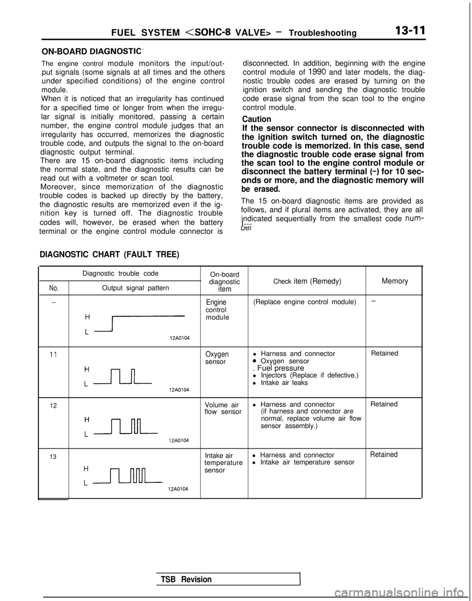
There are 15 on-board diagnostic items including
the normal state, and the diagnostic results can be
read out with a voltmeter or scan tool.
Moreover, since memorization of the diagnostic
trouble codes is backed up directly by the battery,
the diagnostic results are memorized even if the ig- nition key is turned off. The diagnostic trouble
codes will, however, be erased when the battery disconnected. In addition, beginning with the engine
control module of
1990 and later models, the diag-
nostic trouble codes are erased by turning on the
ignition switch and sending the diagnostic trouble
code erase signal from the scan tool to the engine
control module.
Caution
If the sensor connector is disconnected with
the ignition switch turned on, the diagnostic
trouble code is memorized. In this case, send
the diagnostic trouble code erase signal from
the scan tool to the engine control module or disconnect the battery terminal (-)
for 10 sec-
onds or more, and the diagnostic memory will
be erased.
The 15 on-board diagnostic items are provided as
follows, and if plural items are activated, they are all
indicated sequentially from the smallest code num-
I---
terminal or the engine control module connector is
uer
DIAGNOSTIC CHART (FAULT TREE)
No.
-
Diagnostic trouble code On-board
diagnostic
Check item (Remedy) MemoryOutput signal patternitem
-Engine(Replace engine control module)
control
:r
module 12A0104
11Oxygenl Harness and connector
Retained
sensor0 Oxygen sensor
:-JLJ--
. Fuel pressure
l Injectors (Replace if defective.)
l Intake air leaks 12A0104
12Volume air
l Harness and connector
Retained
flow sensor (if harness and connector are
:-JJ-M-
normal, replace volume air flow
sensor assembly.) 12A0104
13 Intake air
l Harness and connector
Retained
temperature l Intake air temperature sensor
:n
sensor 12A0104
TSB Revision
Page 158 of 1273

13-16
FUEL SYSTEM
FAILSAFE/BACK-UP FUNCTIONS LIST
If trouble with any major sensor is detected by the on-board diagnostic,\
the vehicle will be kept in the safe
driving conditions according to the preset control logic.
Trouble item Control content for trouble
Volume air flow Fuel injection timing and ignition timing are determined according to th\
e throttle position
sensor sensor
(TPS) and engine revolution speed signal (crankshaft position sensor signal)\
.
Intake air temperature The control is executed with the suction air temperature regarded as
25°C (77°F).
sensor
Throttle position The fuel injection rate is not increased for acceleration according to t\
he throttle position
sensor
(TPS)sensor signal.
Idle speed control After the idle speed control motor plunger is driven and contracted, the\
idle revolution speed
motor position sensor is not controlled.
Engine coolant The control is executed with the engine coolant temperature regarded as \
8OO.C (176°F).temperature sensor (Even if the sensor signal becomes normal again, the control is continued
until the ignltlon
switch is turned off.)
Camshaft position Simultaneous injection of fuel is executed for all cylinders. (In this \
case, the
No.1 cylinder top
sensor dead center is not detected at all after the ignition key is turned on.)\
Barometric pressure The control is executed with the pressure regarded as 760 mmHg
(30
in.Hg).
sensor
Oxygen sensor Closed loop control of the air/fuel mixture ratio is not executed.
i
READ OUT OF DIAGNOSTIC TROUBLE CODE
Precautions for operation
(1) When battery voltage is low, no detection of failure is possible. Be sure to check the battery for voltage and
other conditions before starting the test.
(2) On-board diagnostic item is erased if the battery or the engine control module connector is discon-
nected. Do not disconnect the battery before the di-
agnostic result is completely read.
Using Scan Tool
(1) Switch OFF the ignition switch.
(2) Connect the power-source terminal of the scan tool to the
cigarette lighter socket.
(3) Connect the scan tool to the data link connector. (4) Turn ignition switch to ON.
(5) Using the scan tool, read out and make a note of the
on-
board diagnostic output.
(6) Refer to the diagnostic chart, and repair the indicated loca-
tion of malfunction.
(7) Erase the diagnostic trouble code. (Refer to
P.13-17.)
1 TSB RevisionI
Page 199 of 1273
FUEL SYSTEM
INSTALLATION
(1) Apply sealant
3M
NUT locking No.41 71 or equivalent to
threaded portion.
(2) Install engine coolant temperature sensor and tighten it to specified torque.
Sensor tightening torque:
20-40 Nm (15-29 ft.lbs.1
(3) Fasten harness connectors securely
THROTTLE POSITION SENSOR
-(‘Throttle position a\“ ’
6FUO637
TerminalvoltageWI
L
Minimum Maximum01 LO838Throttle shaft turning angle162461
Component side
Throttle position sensor
connector
olAO336
Engine control module connector Ml3YJAE
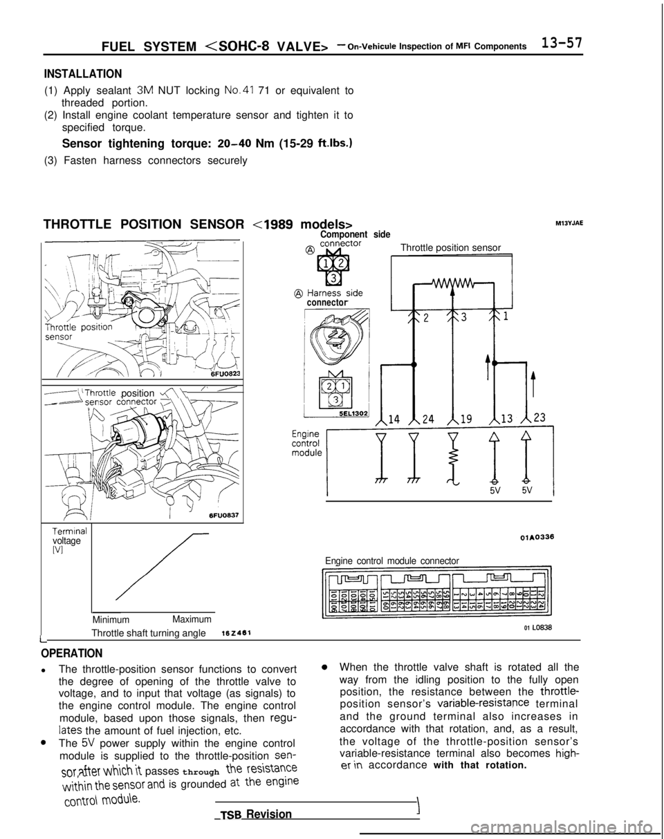
OPERATION
l
The throttle-position sensor functions to convert0When the throttle valve shaft is rotated all the
the degree of opening of the throttle valve to way from the idling position to the fully open
voltage, and to input that voltage (as signals) to position, the resistance between the throttle-
the engine control module. The engine control position sensor’s variable-resistapce
terminal
module, based upon those signals, then regu-
and the ground terminal also increases in
lates the amount of fuel injection, etc. accordance with that rotation, and, as a result,0The 5V power supply within the engine control
the voltage of the throttle-position sensor’s
module is supplied to the throttle-position sen-
variable-resistance terminal also becomes high-
SOT after which it passes through the
resistanceer in
accordance with that rotation.
w&in the sensor and is grounded at the engine
COMO\
module.
TSB RevisionI
Page 203 of 1273
FUEL SYSTEM
CLOSED THROTTLE POSITION SWITCH
control -Idle speed control
motor connector
@ Component sideconnector
@ Harness sideconnector
II
ISC plunger
_---__
III*Throttle shaft turning angle
01209
2
-
Engine control module
1
6
3
OFF
aI
ON
-z
Closed throttleDosition switch
lFUO479
OPERATION
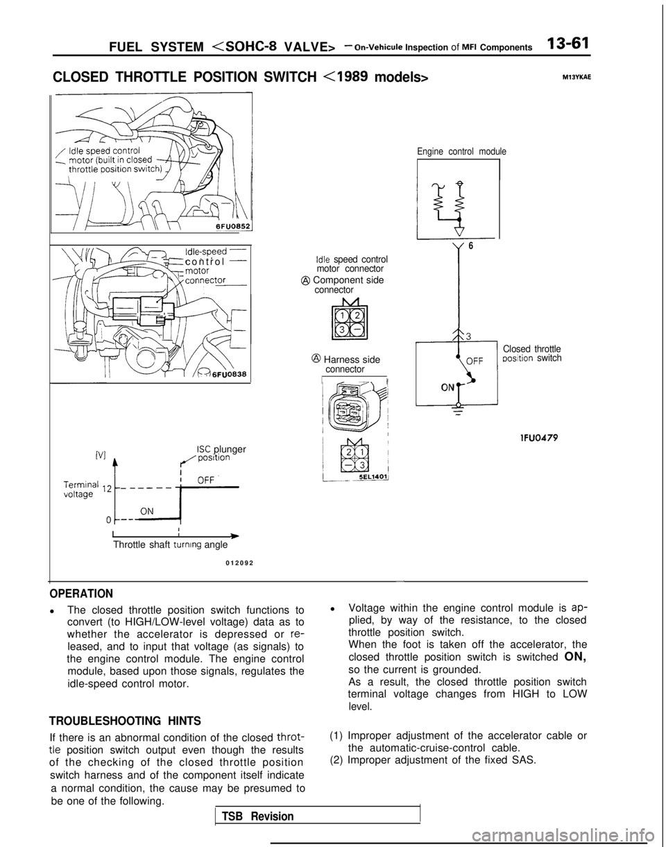
l
The closed throttle position switch functions to
convert (to HIGH/LOW-level voltage) data as to
whether the accelerator is depressed or
re-
leased, and to input that voltage (as signals) to
the engine control module. The engine control module, based upon those signals, regulates the
idle-speed control motor.
TROUBLESHOOTING HINTS
l Voltage within the engine control module is ap-
plied, by way of the resistance, to the closed
throttle position switch.
When the foot is taken off the accelerator, the
closed throttle position switch is switched ON,
so the current is grounded.
As a result, the closed throttle position switch
terminal voltage changes from HIGH to LOW
level.
If there is an abnormal condition of the closed throt-
tle position switch output even though the results
of the checking of the closed throttle position
switch harness and of the component itself indicate
a normal condition, the cause may be presumed tobe one of the following.
TSB Revision
(1) Improper adjustment of the accelerator cable or the automatic-cruise-control cable.
(2) Improper adjustment of the fixed SAS.
Page 224 of 1273
13-82 FUEL SYSTEM
OPERATION
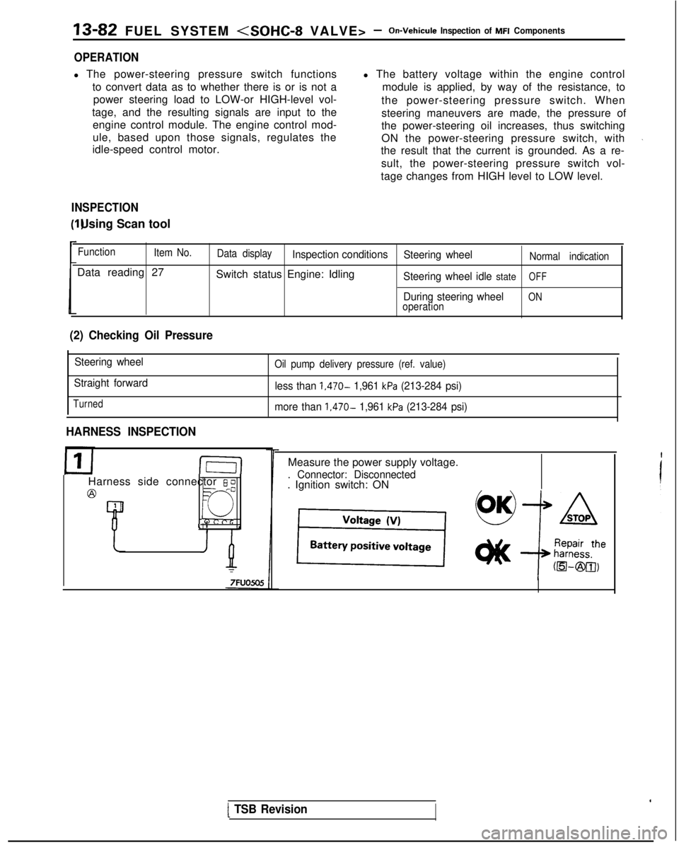
l The power-steering pressure switch functions
to convert data as to whether there is or is not apower steering load to LOW-or HIGH-level vol-
tage, and the resulting signals are input to the engine control module. The engine control mod-
ule, based upon those signals, regulates the
idle-speed control motor. l The battery voltage within the engine control
module is applied, by way of the resistance, to
the power-steering pressure switch. When
steering maneuvers are made, the pressure of
the power-steering oil increases, thus switching
ON the power-steering pressure switch, with
the result that the current is grounded. As a re-
sult, the power-steering pressure switch vol-
tage changes from HIGH level to LOW level.
INSPECTION I) Using Scan tool
Function
Item No.
Data reading 27
Data displayInspection conditions Steering wheelNormal indication
Switch status Engine: IdlingSteering wheel idle stateOFF
During steering wheelONoperation
(2) Checking Oil Pressure
Steering wheel
Straight forward
Turned
Oil pump delivery pressure (ref. value)
less than 1,470- 1,961 kPa (213-284 psi)
more than
1,470- 1,961 kPa (213-284 psi)
HARNESS INSPECTION
I-E-I
Harness side connector 6 0
@=- -0
Q
4 1
Measure the power supply voltage.
. Connector: Disconnected. Ignition switch: ON
[ TSB Revision
Page 227 of 1273
FUEL SYSTEnrll (SOHC-8 VALVE> -On-Vehicule
Inspection of MFI Components13-85
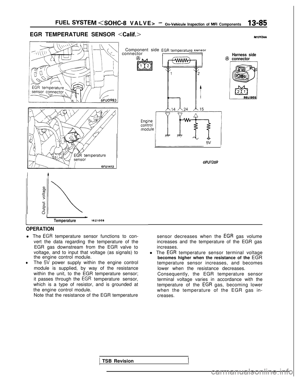
EGR TEMPERATURE SENSOR
\+\+I connectorComponent side EGR temperaturn r-n~nrrHarness side@
connector 6FlJ1412
1
IwTemperaturelEzlooB
OPERATION
l The EGR temperature sensor functions to con-
vert the data regarding the temperature of the EGR gas downstream from the EGR valve to
voltage, and to input that voltage (as signals) to
the engine control module.
lThe 5V power supply within the engine control
module is supplied, by way of the resistance
within the unit, to the EGR temperature sensor; it passes through the
EGR temperature sensor,
which is a type of resistor, and is grounded at
the engine control module. Note that the resistance of the EGR temperature
6FU1269
sensor decreases when the EGR gas volume
increases and the temperature of the EGR gas
increases.
l The EGR temperature sensor terminal voltage
becomes higher when the resistance of the EGR
temperature sensor increases, and becomes
lower when the resistance decreases.
Consequently, the EGR temperature sensor
terminal voltage varies in accordance with the
temperature of the
EGR gas, becoming lower
when the temperature of the EGR gas in-
creases.
TSB RevisionI
Page 262 of 1273
13-120FUEL SYSTEM
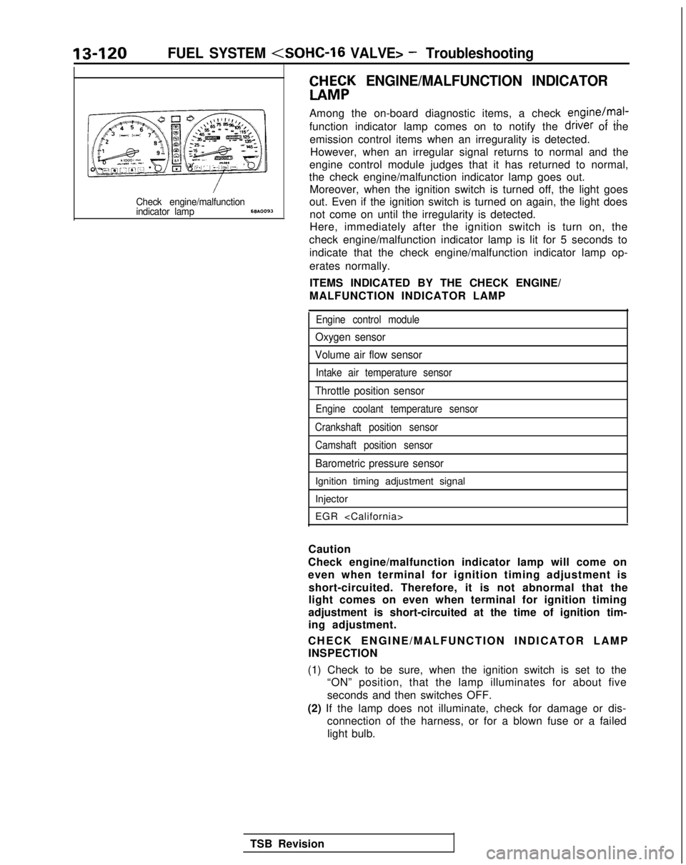
CHH;K
ENGINE/MALFUNCTION INDICATOR
Among the on-board diagnostic items, a check engine/mal-
function indicator lamp comes on to notify the driver
of the
emission control items when an irregurality is detected. However, when an irregular signal returns to normal and the
engine control module judges that it has returned to normal,
the check engine/malfunction indicator lamp goes out. Moreover, when the ignition switch is turned off, the light goes
Check engine/malfunctionout. Even if the ignition switch is turned on again, the light doesindicator lamp68A.0093not come on until the irregularity is detected.
Here, immediately after the ignition switch is turn on, the
check engine/malfunction indicator lamp is lit for 5 seconds to indicate that the check engine/malfunction indicator lamp op-
erates normally.
ITEMS INDICATED BY THE CHECK ENGINE/
MALFUNCTION INDICATOR LAMP
Engine control module
Oxygen sensor
Volume air flow sensor
Intake air temperature sensor
Throttle position sensor
Engine coolant temperature sensor
Crankshaft position sensor Camshaft position sensor
Barometric pressure sensor
Ignition timing adjustment signal
Injector
EGR
Caution
Check engine/malfunction indicator lamp will come on
even when terminal for ignition timing adjustment is short-circuited. Therefore, it is not abnormal that the
light comes on even when terminal for ignition timing
adjustment is short-circuited at the time of ignition tim-
ing adjustment.
CHECK ENGINE/MALFUNCTION INDICATOR LAM
P
INSPECTION
(1) Check to be sure, when the ignition switch is set to the “ON” position, that the lamp illuminates for about five
seconds and then switches OFF.
(2) If the lamp does not illuminate, check for damage or dis- connection of the harness, or for a blown fuse or a failedlight bulb.
TSB Revision
Page 263 of 1273
FUEL SYSTEM
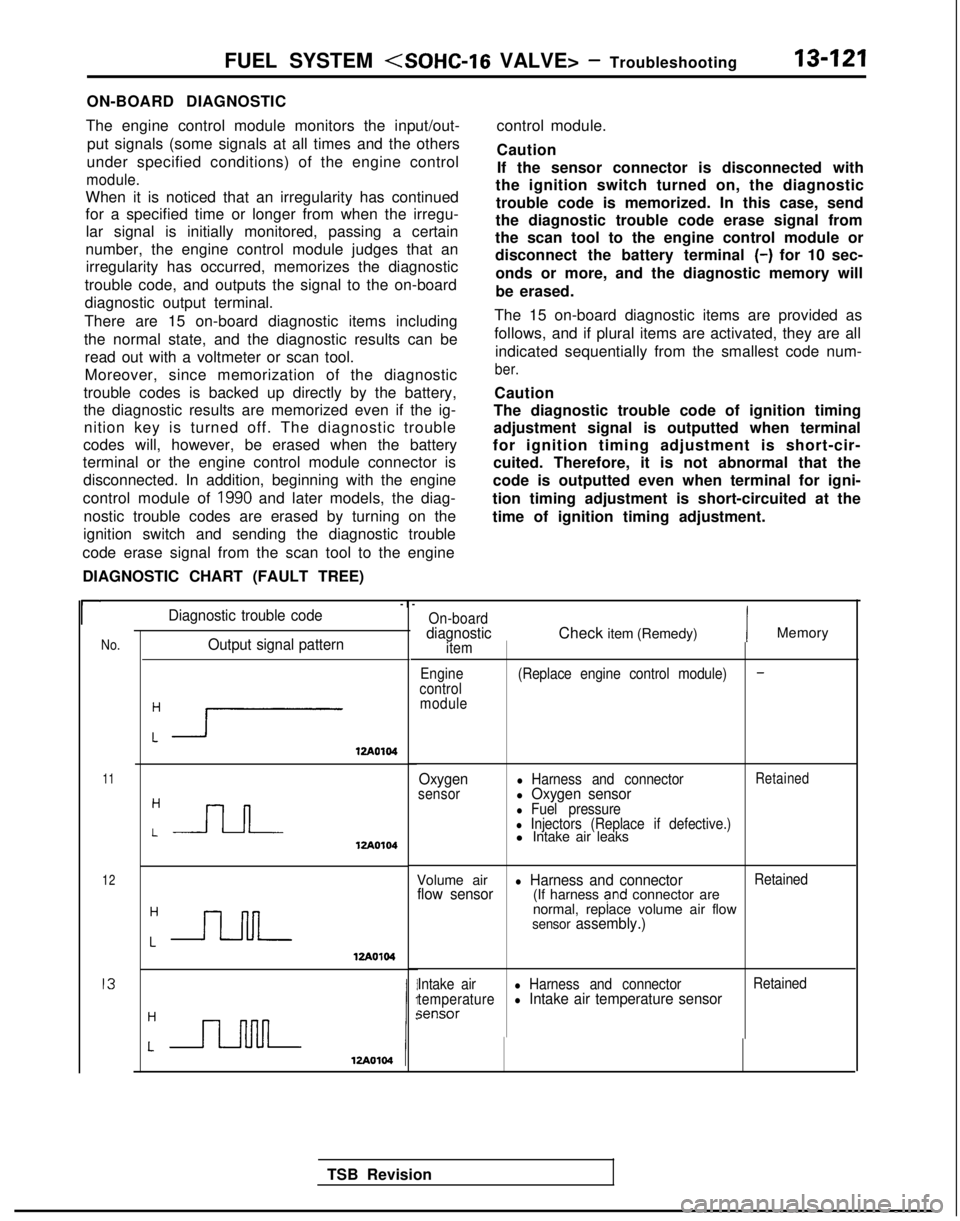
ON-BOARD DIAGNOSTIC
The engine control module monitors the input/out- put signals (some signals at all times and the others
under specified conditions) of the engine control
module.
When it is noticed that an irregularity has continued
for a specified time or longer from when the irregu- lar signal is initially monitored, passing a certain
number, the engine control module judges that an irregularity has occurred, memorizes the diagnostic
trouble code, and outputs the signal to the on-board
diagnostic output terminal.
There are 15 on-board diagnostic items including
the normal state, and the diagnostic results can be read out with a voltmeter or scan tool.
Moreover, since memorization of the diagnostic
trouble codes is backed up directly by the battery,
the diagnostic results are memorized even if the ig- nition key is turned off. The diagnostic trouble
codes will, however, be erased when the battery
terminal or the engine control module connector is
disconnected. In addition, beginning with the engine
control module of
1990 and later models, the diag-
nostic trouble codes are erased by turning on the
ignition switch and sending the diagnostic trouble
code erase signal from the scan tool to the engine
DIAGNOSTIC CHART (FAULT TREE) control module.
Caution
If the sensor connector is disconnected with
the ignition switch turned on, the diagnostic
trouble code is memorized. In this case, send
the diagnostic trouble code erase signal from
the scan tool to the engine control module or
disconnect the battery terminal
(-) for 10 sec-
onds or more, and the diagnostic memory will
be erased.
The 15 on-board diagnostic items are provided as
follows, and if plural items are activated, they are all indicated sequentially from the smallest code num-
ber.
Caution
The diagnostic trouble code of ignition timing
adjustment signal is outputted when terminal
for ignition timing adjustment is short-cir- cuited. Therefore, it is not abnormal that the
code is outputted even when terminal for igni-
tion timing adjustment is short-circuited at the
time of ignition timing adjustment.
r
No.Output signal pattern
:i1zA0104
11
12
I3
:-J-l-J-12Ao104
Diagnostic trouble code-I
-
On-boarddiagnosticitem
Engine
control moduleCheck item (Remedy)IMemory
(Replace engine control module)-
Oxygensensorl Harness and connectorRetainedl Oxygen sensorl Fuel pressurel Injectors (Replace if defective.)l Intake air leaks
Volume air
l Harness and connectorRetainedflow sensor(If harness and connector are
normal, replace volume air flow
sensor assembly.)
Intake airl Harness and connector Retained
temperaturel Intake air temperature sensorsensor
TSB Revision
Page 268 of 1273

13-126FUEL SYSTEM
FAILSAFE/BACK-UP FUNCTIONS LIST
If trouble with any major sensor is detected by the on-board diagnostic,\
the vehicle will be kept in the safe
driving conditions according to the preset control logic.
Trouble item Control content for trouble
Volume air flow(1)Fuel injection timing and ignition timing are determined according to th\
e throttle positionsensorsensor (TPS) and engine revolution speed signal (crankshaft position \
sensor signal).(2)The IAC motor is fixed in the appointed position so idle air control is not per\
formed.
Intake air temperature The control is executed with the suction air temperature regarded as
25°C (77°F).sensor
Throttle position The fuel injection rate is not increased for acceleration according to t\
he throttle position
sensor (TPS)sensor signal.
Engine coolantThe control is executed with the coolant temperature regarded as 80°C (176’F).temperature sensor
Camshaft positionSimultaneous injection of fuel is executed for all cylinders. (In this \
case, the
No.1 cylinder top
jenS0r
dead center is not detected at all after the ignition key is turned
on.)3arometric
pressure The control is executed with the pressure regarded as 760 mmHg
(30 in. Hg.).
sensor
AC valve position Idle air control motor is not performed.;ensor
Ixygen sensor
Closed loop control of the air/fuel mixture ratio is not executed.
READ OUT OF DIAGNOSTIC TROUBLE CODE
Refer to P.13-16.
EbW&R MEMORY OF DIAGNOSTIC TROUBLE
Refer to
P.13-17.
TSB Revision