lock MITSUBISHI GRANDIS 2010 Owner's Manual (in English)
[x] Cancel search | Manufacturer: MITSUBISHI, Model Year: 2010, Model line: GRANDIS, Model: MITSUBISHI GRANDIS 2010Pages: 273, PDF Size: 21.01 MB
Page 2 of 273
Table of contents
Overview
General information
Locking and unlocking 1
Seat and seat belts 2
Instruments and controls 3
Starting and driving 4
For pleasant driving 5
For emergencies 6
Vehicle care 7
Maintenance 8
Specifications 9
Presented by http://mmc-manuals.ru/ \251
Page 7 of 273
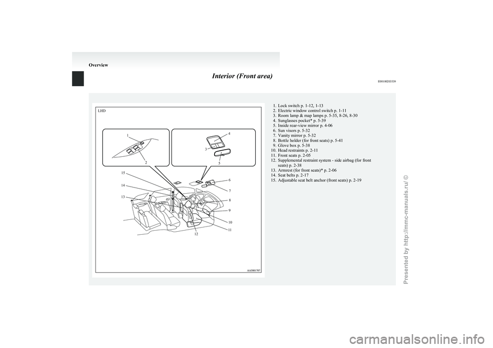
Interior (Front area)
E00100203539 1. Lock switch p. 1-12, 1-13
2.
Electric window control switch p. 1-11
3. Room lamp & map lamps p. 5-35, 8-26, 8-30
4. Sunglasses pocket* p. 5-39
5. Inside rear-view mirror p. 4-06
6. Sun visors p. 5-32
7. Vanity mirror p. 5-32
8. Bottle holder (for front seats) p. 5-41
9. Glove box p. 5-38
10. Head restraints p. 2-11
11. Front seats p. 2-05
12. Supplemental restraint system - side airbag (for front seats) p. 2-38
13. Armrest (for front seats)* p. 2-06
14. Seat belts p. 2-17
15. Adjustable seat belt anchor (front seats) p. 2-19 OverviewLHD
1
2 34
5 67
8
9
10
1
1
12
13 14
15
Presented by http://mmc-manuals.ru/ \251
Page 8 of 273
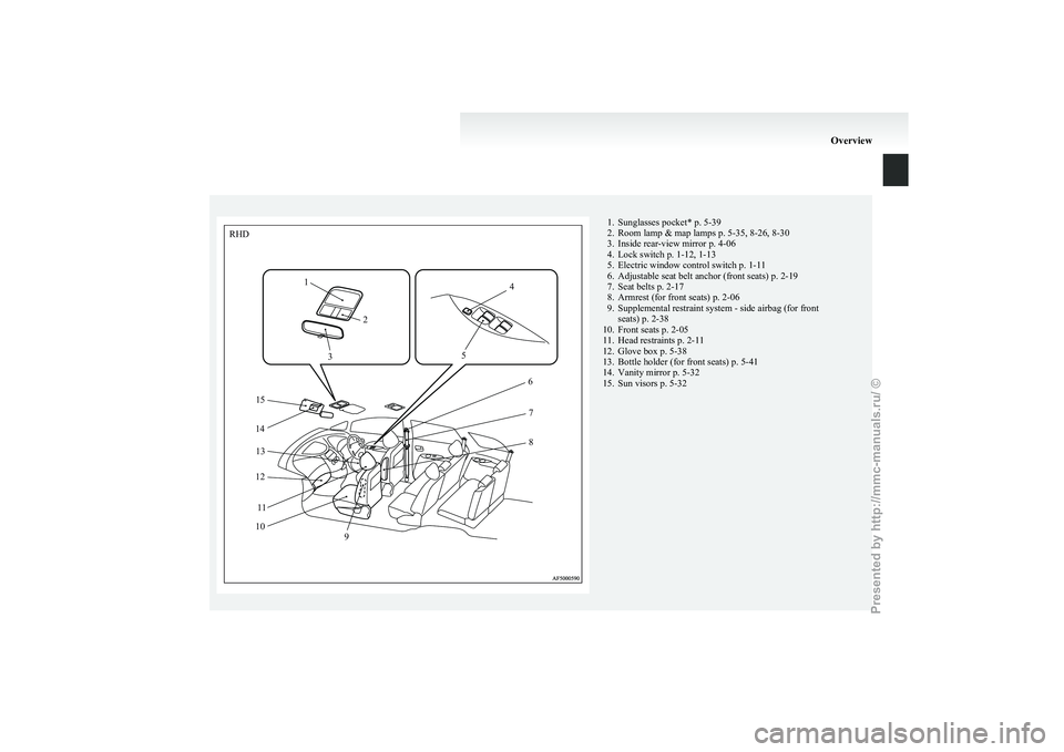
1. Sunglasses pocket* p. 5-39
2.
Room lamp & map lamps p. 5-35, 8-26, 8-30
3. Inside rear-view mirror p. 4-06
4. Lock switch p. 1-12, 1-13
5. Electric window control switch p. 1-11
6. Adjustable seat belt anchor (front seats) p. 2-19
7. Seat belts p. 2-17
8. Armrest (for front seats) p. 2-06
9. Supplemental restraint system - side airbag (for front seats) p. 2-38
10. Front seats p. 2-05
11. Head restraints p. 2-11
12. Glove box p. 5-38
13. Bottle holder (for front seats) p. 5-41
14. Vanity mirror p. 5-32
15. Sun visors p. 5-32 Overview1
2
3 4
5 6
7
8
RH
D
9
10 11
12
13
14 15
Presented by http://mmc-manuals.ru/ \251
Page 13 of 273
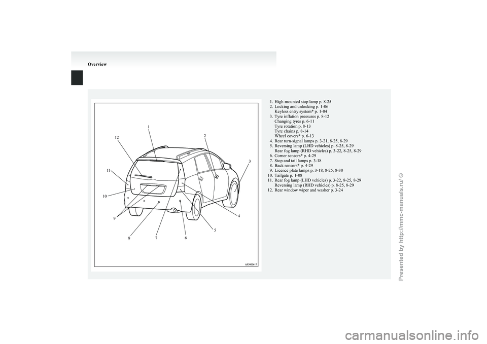
1. High-mounted stop lamp p. 8-25
2.
Locking and unlocking p. 1-06Keyless entry system* p. 1-04
3. Tyre inflation pressures p. 8-12 Changing tyres p. 6-11
Tyre rotation p. 8-13
Tyre chains p. 8-14
Wheel covers* p. 6-13
4. Rear turn-signal lamps p. 3-21, 8-25, 8-29
5. Reversing lamp (LHD vehicles) p. 8-25, 8-29 Rear fog lamp (RHD vehicles) p. 3-22, 8-25, 8-29
6. Corner sensors* p. 4-29
7. Stop and tail lamps p. 3-18
8. Back sensors* p. 4-29
9. Licence plate lamps p. 3-18, 8-25, 8-30
10. Tailgate p. 1-08
11. Rear fog lamp (LHD vehicles) p. 3-22, 8-25, 8-29 Reversing lamp (RHD vehicles) p. 8-25, 8-29
12. Rear window wiper and washer p. 3-24 Overview1
2
3
4
5
6
7
8
9
10 1
1 12
Presented by http://mmc-manuals.ru/ \251
Page 16 of 273
Filling the fuel tank
E00200202142WARNING
l Petrol is highly flammable and explosive.
You could be burned or seriously injured
when handling it. When refueling your ve-
hicle, always turn the engine off and keep
away from flames, sparks, and smoking
materials. Always handle fuel in well-ven-
tilated outdoor areas.
l Before removing the fuel cap, be sure to
get rid of your body’s static electricity by
touching a metal part of the car or the
fuel pump. Any static electricity on your
body could create a spark that ignites
fuel vapour.
l Perform the whole refueling process
(opening the fuel tank filler door, remov-
ing the fuel cap, etc.) by yourself. Do not
let any other person come near the fuel
tank filler. If you allowed a person to
help you and that person was carrying
static electricity, fuel vapour could be ig-
nited.
l Do not move away from the fuel tank fill-
er until refueling is finished. If you
moved away and did something else (for
example, cleaning your windscreen) part-
way through the refueling process, you
could pick up a fresh charge of static elec-
tricity.
l Be careful not to inhale fuel vapour. Fuel
contains toxic substances. WARNING
l Keep
the doors and windows closed while
refueling the vehicle. If they were open,
fuel vapour could get into the cabin.
Fuel tank capacity
65 litres
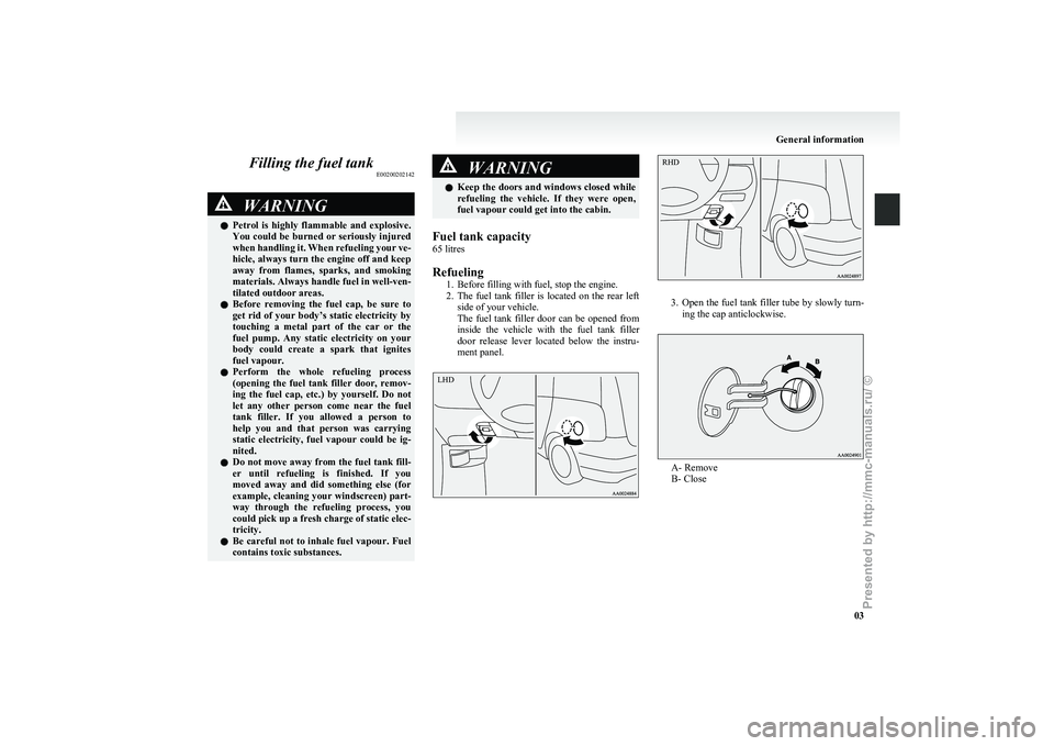
Refueling 1.
Before filling with fuel, stop the engine.
2. The fuel tank filler is located on the rear left side of your vehicle.
The fuel tank filler door can be opened from
inside the vehicle with the fuel tank filler
door release lever located below the instru-
ment panel. 3. Open
the fuel tank filler tube by slowly turn-
ing the cap anticlockwise. A- Remove
B- Close General information
03 LHD RHD
Presented by http://mmc-manuals.ru/ \251
Page 17 of 273
CAUTION
l
Since the fuel system may be under pres-
sure, remove the fuel tank filler tube cap
slowly. This relieves any pressure or vac-
uum that might have built up in the fuel
tank. If you hear a hissing sound, wait un-
til it stops before removing the cap. Oth-
erwise, fuel may spray out, injuring you
or others.
4. To
fill with fuel correctly depends mainly on correct handling of the fuel filler gun. Do not
tilt the gun. Insert the gun in the tank port as
far as it goes. CAUTION
l
A
label which reads “UNLEADED FUEL
ONLY” is attached to the fuel tank filler
lid of vehicles which can only operate us-
ing unleaded petrol. Serious engine and
catalytic converter damage will result if
leaded petrol is filled into these vehicles,
and consequently, this must never be at-
tempted.
5. When
the gun stops automatically, do not fill with fuel any more. CAUTION
l
To
avoid fuel spillage and overfilling, do
not “top-off” the fuel tank. 6. To
close, turn the fuel tank filler tube cap
slowly clockwise until you hear clicking
sounds, then gently push the fuel tank filler
door closed. CAUTION
l
If
you need to replace the fuel tank filler
tube cap, use only the cap specified for
your model vehicle. Installation of accessories
E00200300745
We
recommend you to consult your MITSUBISHI
MOTORS Authorized Service Point.
l The installation of accessories, optional
parts, etc., should only be carried out within
the limits prescribed by law in your country,
and in accordance with the guidelines fitting
instructions and warnings contained within
the documents accompanying the parts or ac-
cessories.
l Improper installation of electrical compo-
nents may cause an electrical fire if incorrect-
ly fitted. Please refer to the Modification/al-
teration to the electrical or fuel systems sec-
tion within this owner’s manual.
l Using a cellular phone or radio set inside the
vehicle without an external antenna may
cause electrical system interference, which
could lead to unsafe vehicle operation.
l Tyres and wheels which do not meet specifi-
cations must not be used.
Refer to the “Specifications” section for in-
formation regarding wheel and tyre sizes.
Important points!
Due to the large number of accessory and replace-
ment parts of different manufactures available in
the market, it is not possible, not only for
MITSUBISHI MOTORS, but also a MITSUBISHI
MOTORS Authorized Service Point, to check
whether the attachment or installation of such parts
affects thedriving safety of your MITSUBISHI-ve-
hicle.
General information
04
Presented by http://mmc-manuals.ru/ \251
Page 20 of 273
Keys..............................................................................................
1-02
Electronic immobilizer (Anti-theft starting system) .....................1-03
Keyless entry system*.................................................................. 1-04
Doors............................................................................................ 1-06
Central door locks ......................................................................... 1-07
Child-protection rear doors ........................................................... 1-08
Tailgate ......................................................................................... 1-08
Inside tailgate release....................................................................1-10
Electric window control................................................................1-11
Sunroof*....................................................................................... 1-13Locking and unlocking
1
Presented by http://mmc-manuals.ru/ \251
Page 21 of 273
Keys
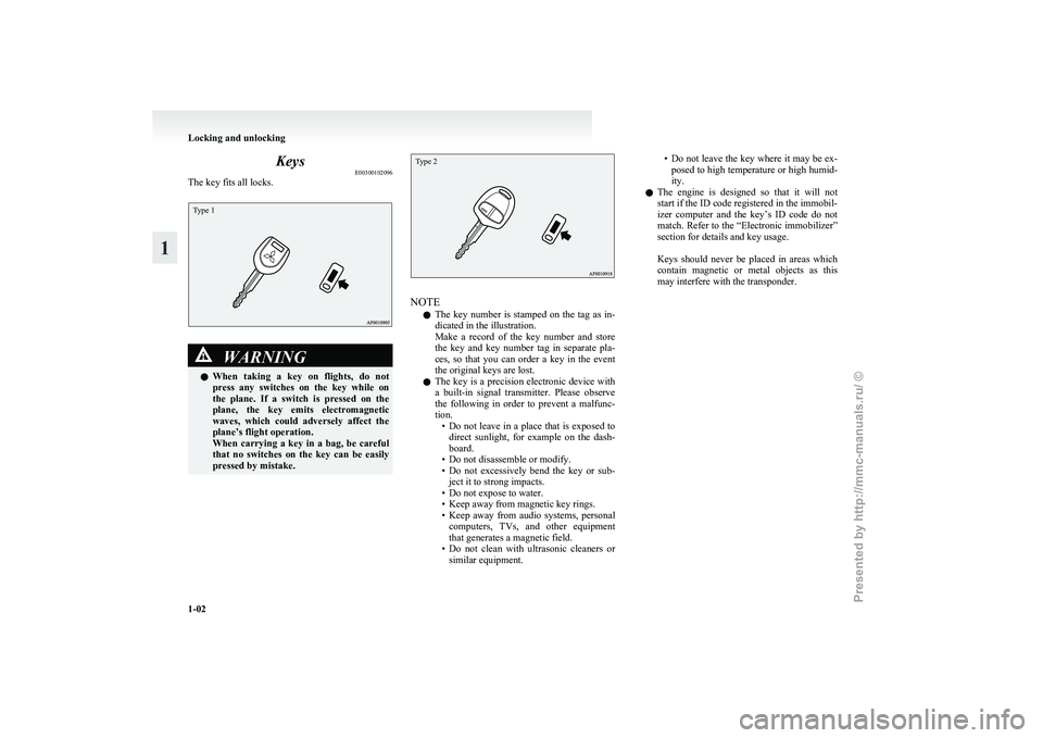
E00300102096
The key fits all locks.Type 1 WARNING
l When
taking a key on flights, do not
press any switches on the key while on
the plane. If a switch is pressed on the
plane, the key emits electromagnetic
waves, which could adversely affect the
plane’s flight operation.
When carrying a key in a bag, be careful
that no switches on the key can be easily
pressed by mistake.
Type 2 NOTE
l The
key number is stamped on the tag as in-
dicated in the illustration.
Make a record of the key number and store
the key and key number tag in separate pla-
ces, so that you can order a key in the event
the original keys are lost.
l The key is a precision electronic device with
a built-in signal transmitter. Please observe
the following in order to prevent a malfunc-
tion.
• Do not leave in a place that is exposed todirect sunlight, for example on the dash-
board.
• Do not disassemble or modify.
• Do not excessively bend the key or sub- ject it to strong impacts.
• Do not expose to water.
• Keep away from magnetic key rings.
• Keep away from audio systems, personal computers, TVs, and other equipment
that generates a magnetic field.
• Do not clean with ultrasonic cleaners or similar equipment. • Do
not leave the key where it may be ex-
posed to high temperature or high humid-
ity.
l The engine is designed so that it will not
start if the ID code registered in the immobil-
izer computer and the key’s ID code do not
match. Refer to the “Electronic immobilizer”
section for details and key usage.
Keys should never be placed in areas which
contain magnetic or metal objects as this
may interfere with the transponder. Locking and unlocking
1-02
1
Presented by http://mmc-manuals.ru/ \251
Page 22 of 273
Electronic immobilizer
(Anti-theft starting system) E00300201553
The
electronic immobilizer is designed to signifi-
cantly reduce the possibility of vehicle theft. The
purpose of the system is to immobilize the vehicle
if an invalid start is attempted. A valid start attempt
can only be achieved (subject to certain conditions)
using a keyless operation system “registered” to
the immobilizer system.
NOTE
l In the following cases, the vehicle may not
be able to receive the registered ID code
from the key. This means the engine will not
start even when the registered key is turned
to the “START” position.
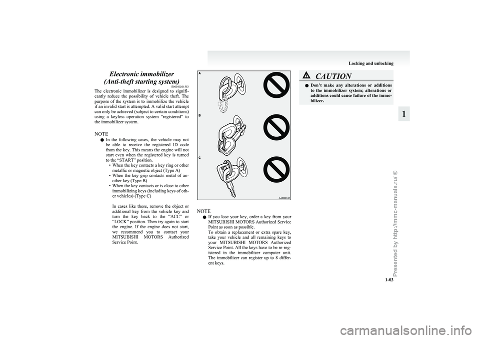
• When the key contacts a key ring or othermetallic or magnetic object (Type A)
• When the key grip contacts metal of an- other key (Type B)
• When the key contacts or is close to other immobilizing keys (including keys of oth-
er vehicles) (Type C)
In cases like these, remove the object or
additional key from the vehicle key and
turn the key back to the “ACC” or
“LOCK” position. Then try again to start
the engine. If the engine does not start,
we recommend you to contact your
MITSUBISHI MOTORS Authorized
Service Point. NOTE
l If
you lose your key, order a key from your
MITSUBISHI MOTORS Authorized Service
Point as soon as possible.
To obtain a replacement or extra spare key,
take your vehicle and all remaining keys to
your MITSUBISHI MOTORS Authorized
Service Point. All the keys have to be re-reg-
istered in the immobilizer computer unit.
The immobilizer can register up to 8 differ-
ent keys. CAUTION
l
Don’t
make any alterations or additions
to the immobilizer system; alterations or
additions could cause failure of the immo-
bilizer. Locking and unlocking
1-03 1
Presented by http://mmc-manuals.ru/ \251
Page 23 of 273
Keyless entry system*
E00300302115
Press
the remote control switch, and all doors and
the tailgate will be locked or unlocked as desired. It
is also possible to operate the outside rear-view mir-
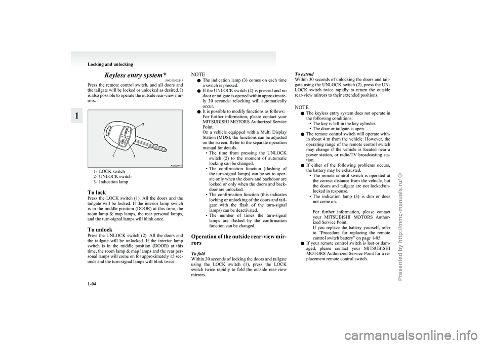
rors. 1- LOCK switch
2-
UNLOCK switch
3- Indication lamp
To lock
Press the LOCK switch (1). All the doors and the
tailgate will be locked. If the interior lamp switch
is in the middle position (DOOR) at this time, the
room lamp & map lamps, the rear personal lamps,
and the turn-signal lamps will blink once.
To unlock
Press the UNLOCK switch (2). All the doors and
the tailgate will be unlocked. If the interior lamp
switch is in the middle position (DOOR) at this
time, the room lamp & map lamps and the rear per-
sonal lamps will come on for approximately 15 sec-
onds and the turn-signal lamps will blink twice. NOTE
l The
indication lamp (3) comes on each time
a switch is pressed.
l If the UNLOCK switch (2) is pressed and no
door or tailgate is opened within approximate-
ly 30 seconds: relocking will automatically
occur.
l It is possible to modify functions as follows:
For further information, please contact your
MITSUBISHI MOTORS Authorized Service
Point.
On a vehicle equipped with a Multi Display
Station (MDS), the functions can be adjusted
on the screen. Refer to the separate operation
manual for details.
• The time from pressing the UNLOCKswitch (2) to the moment of automatic
locking can be changed.
• The confirmation function (flashing of the turn-signal lamps) can be set to oper-
ate only when the doors and backdoor are
locked or only when the doors and back-
door are unlocked.
• The confirmation function (this indicates locking or unlocking of the doors and tail-
gate with the flash of the turn-signal
lamps) can be deactivated.
• The number of times the turn-signal lamps are flashed by the confirmation
function can be changed.
Operation of the outside rear-view mir-
rors
To fold
Within 30 seconds of locking the doors and tailgate
using the LOCK switch (1), press the LOCK
switch twice rapidly to fold the outside rear-view
mirrors. To extend
Within
30 seconds of unlocking the doors and tail-
gate using the UNLOCK switch (2), press the UN-
LOCK switch twice rapidly to return the outside
rear-view mirrors to their extended positions.
NOTE
l The keyless entry system does not operate in
the following conditions:
• The key is left in the key cylinder.
• The door or tailgate is open.
l The remote control switch will operate with-
in about 4 m from the vehicle. However, the
operating range of the remote control switch
may change if the vehicle is located near a
power station, or radio/TV broadcasting sta-
tion.
l If either of the following problems occurs,
the battery may be exhausted.
• The remote control switch is operated atthe correct distance from the vehicle, but
the doors and tailgate are not locked/un-
locked in response.
• The indication lamp (3) is dim or does not come on.
For further information, please contact
your MITSUBISHI MOTORS Author-
ized Service Point.
If you replace the battery yourself, refer
to “Procedure for replacing the remote
control switch battery” on page 1-05.
l If your remote control switch is lost or dam-
aged, please contact your MITSUBISHI
MOTORS Authorized Service Point for a re-
placement remote control switch. Locking and unlocking
1-04
1
Presented by http://mmc-manuals.ru/ \251