bulb MITSUBISHI I-MIEV 2011 Owners Manual
[x] Cancel search | Manufacturer: MITSUBISHI, Model Year: 2011, Model line: I-MIEV, Model: MITSUBISHI I-MIEV 2011Pages: 193, PDF Size: 12.2 MB
Page 78 of 193
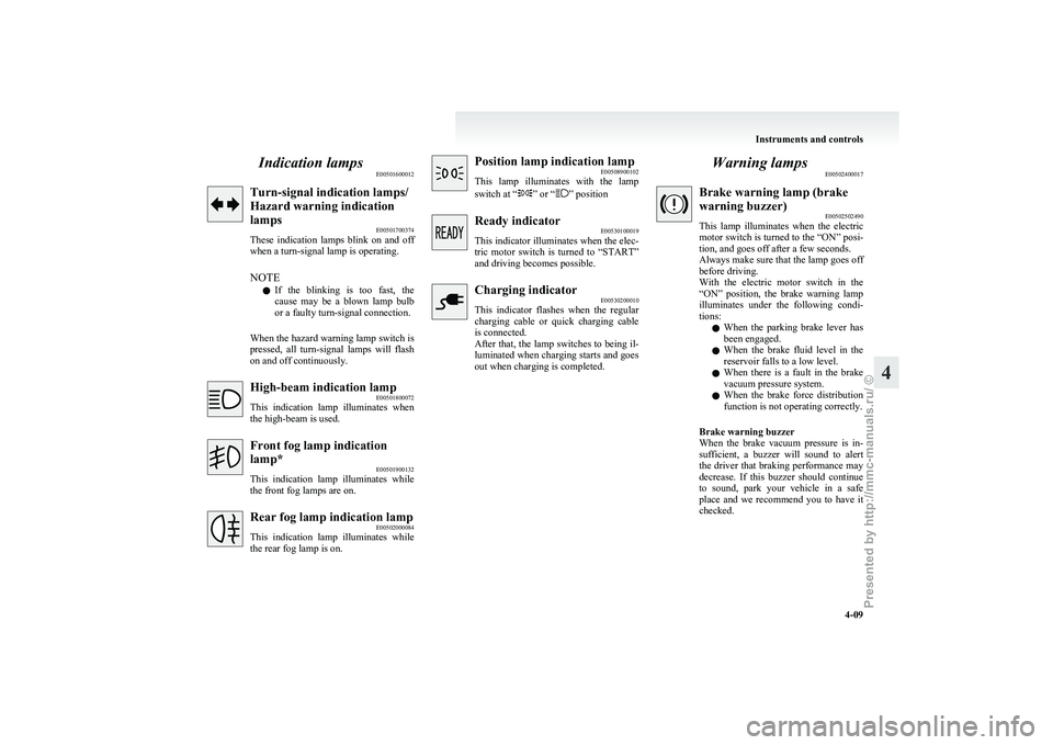
Indication lamps
E00501600012Turn-signal indication lamps/
Hazard warning indication
lamps
E00501700374
These
indication lamps blink on and off
when a turn-signal lamp is operating.
NOTE
l If the blinking is too fast, the
cause may be a blown lamp bulb
or a faulty turn-signal connection.
When the hazard warning lamp switch is
pressed, all turn-signal lamps will flash
on and off continuously. High-beam indication lamp
E00501800072
This
indication lamp illuminates when
the high-beam is used. Front fog lamp indication
lamp*
E00501900132
This
indication lamp illuminates while
the front fog lamps are on. Rear fog lamp indication lamp
E00502000084
This
indication lamp illuminates while
the rear fog lamp is on. Position lamp indication lamp
E00508900102
This
lamp illuminates with the lamp
switch at “ ” or “ ” position
Ready indicator
E00530100019
This
indicator illuminates when the elec-
tric motor switch is turned to “START”
and driving becomes possible. Charging indicator
E00530200010
This
indicator flashes when the regular
charging cable or quick charging cable
is connected.
After that, the lamp switches to being il-
luminated when charging starts and goes
out when charging is completed. Warning lamps
E00502400017 Brake warning lamp (brake
warning buzzer)
E00502502490
This
lamp illuminates when the electric
motor switch is turned to the “ON” posi-
tion, and goes off after a few seconds.
Always make sure that the lamp goes off
before driving.
With the electric motor switch in the
“ON” position, the brake warning lamp
illuminates under the following condi-
tions:
l When the parking brake lever has
been engaged.
l When the brake fluid level in the
reservoir falls to a low level.
l When there is a fault in the brake
vacuum pressure system.
l When the brake force distribution
function is not operating correctly.
Brake warning buzzer
When the brake vacuum pressure is in-
sufficient, a buzzer will sound to alert
the driver that braking performance may
decrease. If this buzzer should continue
to sound, park your vehicle in a safe
place and we recommend you to have it
checked. Instruments and controls
4-09 4
Presented by http://mmc-manuals.ru/ \251
Page 83 of 193
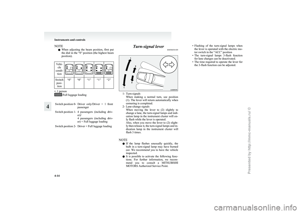
NOTE
l When
adjusting the beam position, first put
the dial in the “0” position (the highest beam
position).
Vehi- cle
condi- tion Switch
posi-tion “0” “0” “1” “1” “2” •: 1 person
:Full luggage loading
Switch position 0- Driver only/Driver + 1 front passenger
Switch position 1- 4 passengers (including driv- er)/
4
passengers (including driv-
er) + Full luggage loading
Switch position 2- Driver + Full luggage loading Turn-signal lever
E00506501459 1- Turn-signals
When
making a normal turn, use position
(1). The lever will return automatically when
cornering is completed.
2- Lane-change signals When moving the lever to (2) slightly to
change a lane, the turn-signal lamps and indi-
cation lamp in the instrument cluster will on-
ly flash while the lever is operated.
Also, when you move the lever to (2) slight-
ly then release it, the turn-signal lamps and in-
dication lamp in the instrument cluster will
flash 3 times.
NOTE l If the lamp flashes unusually quickly, the
bulb in a turn-signal lamp may have burned
out. We recommend you to have the vehicle
inspected.
l It is possible to activate the following func-
tions. For further information, we recom-
mend you to consult a MITSUBISHI
MOTORS Authorized Service Point. • Flashing
of the turn-signal lamps when
the lever is operated with the electric mo-
tor switch in the “ACC” position
• The turn-signal lamps 3-flash function for lane changes can be deactivated.
• The time required to operate the lever for the 3-flash function can be adjusted. Instruments and controls
4-14
4
Presented by http://mmc-manuals.ru/ \251
Page 101 of 193
Inspection and maintenance
following rough road operation E00606700383
After
operating the vehicle in rough road condi-
tions, be sure to perform the following inspection
and maintenance procedures:
l Check that the vehicle has not been damaged
by rocks, gravel, etc.
l Carefully wash the vehicle with water.
Drive the vehicle slowly while lightly depress-
ing the brake pedal in order to dry out the
brakes. If the brakes still do not function prop-
erly, we recommend you to have the brakes
checked as soon as possible.
l Remove the insects, dried grass, etc. clog-
ging the radiator core.
l Check the inside of the vehicle. If water en-
try is found, dry the carpet etc.
l Inspect the headlamps, If the headlamp bulb
is flooded with water, we recommend you to
have it drained. Braking
E00607001830
All
the parts of the brake system are critical to safe-
ty. We recommend you to have the vehicle
checked at regular intervals according to the serv-
ice booklet. CAUTION
l
Avoid
driving habits that cause heavy
braking and never “ride” the brakes by
resting your foot on the brake pedal
while driving.
It causes brake overheating and fading.
Brake system
The
service brake is divided into two brake cir-
cuits. And your vehicle is equipped with power
brakes. If one brake circuit fails, the other is availa-
ble to stop the vehicle. If you should lose the pow-
er assist for some reason, the brakes will still work.
In these situations, even if the brake pedal moves
down to the very end of its possible stroke or re-
sists being depressed, keep depressing the brake ped-
al down harder and further than usual; stop driving
as soon as possible and have the brake system re-
paired. WARNING
l Do
not turn off the electric motor unit
while your vehicle is in motion. If you
turn off the electric motor unit while driv-
ing, the power assistance for the braking
system will stop working and your brakes
will not work effectively. WARNING
l If
the power assist is lost or if either
brake hydraulic system stops working
properly, have your vehicle checked im-
mediately.
Warning lamp
The
brake warning lamp illuminates to indicate a
fault in the braking system. Refer to “Brake warn-
ing lamp” on page 4-09.
When brakes are wet
Check the brake system while driving at a low
speed immediately after starting, especially when
the brakes are wet, to confirm they work normally.
A film of water can be formed on the brake discs
or brake drums and prevent normal braking after
driving in heavy rain or through large puddles, or
after the vehicle is washed. If this occurs, dry the
brakes out by driving slowly while lightly depress-
ing the brake pedal.
When driving downhill
It is important to take advantage of regenerative
braking by shifting to the “B” (BRAKE) position
while driving on steep downhill roads in order to
prevent the brakes from overheating. Starting and driving
5-12
5
Presented by http://mmc-manuals.ru/ \251
Page 140 of 193
Vehicle care precautions
............................................................... 8-02
Cleaning the interior of your vehicle ............................................8-02
Cleaning the exterior of your vehicle ...........................................8-03
Service precautions ....................................................................... 8-06
Bonnet...........................................................................................8-07
Coolant/Hot water heater fluid ..................................................... 8-09
Washer fluid ................................................................................. 8-11
Brake fluid .................................................................................... 8-11
Auxiliary battery ........................................................................... 8-12
Tyres............................................................................................. 8-14
Wiper blades ................................................................................. 8-17
General maintenance .................................................................... 8-19
For cold and snowy weather......................................................... 8-20
Fusible links.................................................................................. 8-20
Fuses............................................................................................. 8-20
Replacement of lamp bulbs .......................................................... 8-23Vehicle care and Maintenance
8
Presented by http://mmc-manuals.ru/ \251
Page 158 of 193
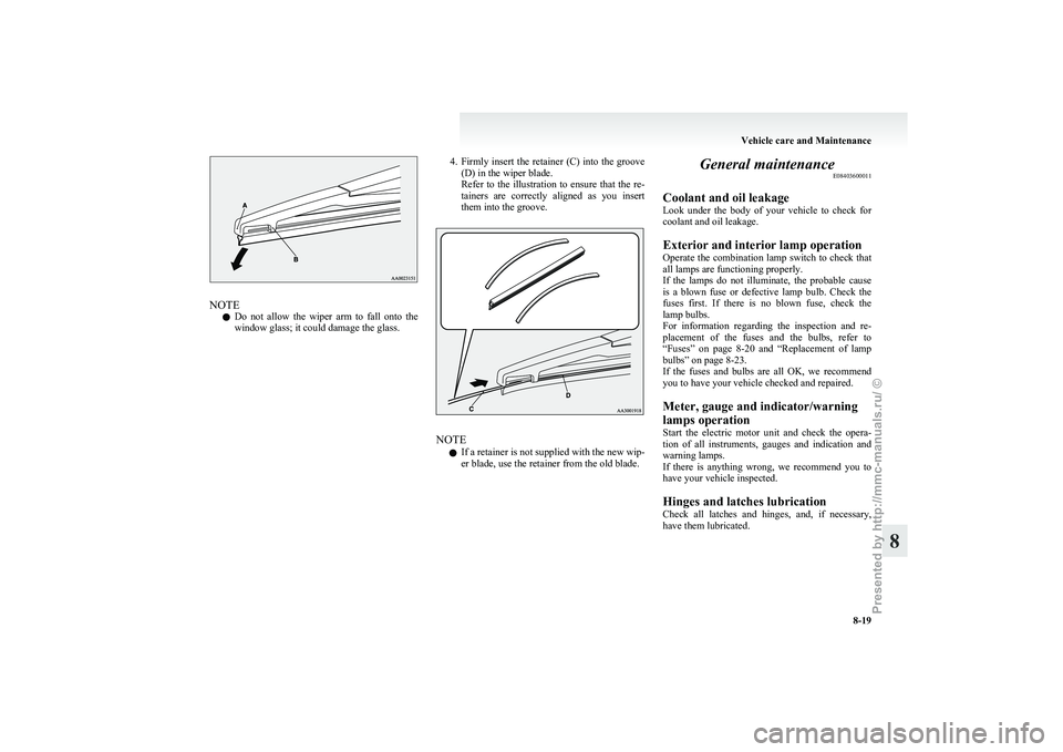
NOTE
l Do
not allow the wiper arm to fall onto the
window glass; it could damage the glass. 4. Firmly
insert the retainer (C) into the groove
(D) in the wiper blade.
Refer to the illustration to ensure that the re-
tainers are correctly aligned as you insert
them into the groove. NOTE
l If
a retainer is not supplied with the new wip-
er blade, use the retainer from the old blade. General maintenance
E08403600011
Coolant and oil leakage
Look
under the body of your vehicle to check for
coolant and oil leakage.
Exterior and interior lamp operation
Operate the combination lamp switch to check that
all lamps are functioning properly.
If the lamps do not illuminate, the probable cause
is a blown fuse or defective lamp bulb. Check the
fuses first. If there is no blown fuse, check the
lamp bulbs.
For information regarding the inspection and re-
placement of the fuses and the bulbs, refer to
“Fuses” on page 8-20 and “Replacement of lamp
bulbs” on page 8-23.
If the fuses and bulbs are all OK, we recommend
you to have your vehicle checked and repaired.
Meter, gauge and indicator/warning
lamps operation
Start the electric motor unit and check the opera-
tion of all instruments, gauges and indication and
warning lamps.
If there is anything wrong, we recommend you to
have your vehicle inspected.
Hinges and latches lubrication
Check all latches and hinges, and, if necessary,
have them lubricated. Vehicle care and Maintenance
8-19 8
Presented by http://mmc-manuals.ru/ \251
Page 162 of 193
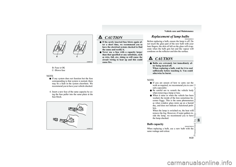
B- Fuse is OK
C- Blown fuse
NOTE l If
any system does not function but the fuse
corresponding to that system is normal, there
may be a fault in the system elsewhere. We
recommend you to have your vehicle checked.
4. Insert a new fuse of the same capacity by us- ing the fuse puller into the same place at the
fuse block. CAUTION
l
If
the newly inserted fuse blows again af-
ter a short time, we recommend you to
have the electrical system checked to find
the cause and rectify it.
l Never use a fuse with a capacity larger
than that specified or any substitute, such
as wire, foil, etc.; doing so will cause the
circuit wiring to heat up and this could
cause fire. Replacement of lamp bulbs
E08404600018
Before
replacing a bulb, ensure the lamp is off. Do
not touch the glass part of the new bulb with your
bare fingers; the skin oil left on the glass will evap-
orate when the bulb gets hot and the vapour will
condense on the reflector and dim the surface. CAUTION
l
Bulbs
are extremely hot immediately af-
ter being turned off.
When replacing a bulb, wait for it to cool
sufficiently before touching it. You could
otherwise be burnt.
NOTE l If
you are unsure of how to carry out the
work as required, we recommend you to con-
sult a specialist.
l Be careful not to scratch the vehicle body
when removing a lamp or lens.
l When it rains or when the vehicle has been
washed, the inside of the lens sometimes be-
comes foggy. This is the same phenomenon
as when window glass mists up on a humid
day, and does not indicate a functional prob-
lem.
When the lamp is switched on, the heat will
remove the fog. However, if water gathers in-
side the lamp, we recommend you to have
the lamp checked.
Bulb capacity E08404700019
When replacing a bulb, use a new bulb with the
same wattage and colour. Vehicle care and Maintenance
8-23 8
Presented by http://mmc-manuals.ru/ \251
Page 163 of 193
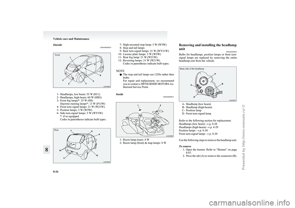
Outside
E08404800010Front1- Headlamps, low beam: 55 W (H11)
2-
Headlamps, high-beam: 60 W (HB3)
3- Front fog lamps*: 35 W (H8) Daytime running lamps*: 13 W (P13W)
4- Front turn-signal lamps: 21 W (W21W)
5- Position lamps: 5 W (W5W)
6- Side turn-signal lamps: 5 W (WY5W) *: if so equipped
Codes in parentheses indicate bulb types.
Rear 7- High-mounted stop lamp: 5 W (W5W)
8-
Stop and tail lamps
9- Rear turn-signal lamps: 21 W (WY21W)
10- Licence plate lamps: 5 W (W5W)
11- Rear fog lamp: 21 W (W21W)
12- Reversing lamps: 21 W (W21W) Codes in parentheses indicate bulb types.
NOTE l The stop and tail lamps use LEDs rather than
bulbs.
For repair and replacement, we recommend
you to contact a MITSUBISHI MOTORS Au-
thorized Service Point.
Inside E08404900011 1- Room lamp (rear): 8 W
2-
Room lamp (front) & map lamps: 8 W Removing and installing the headlamp
unit
E08405000022
Bulbs
for headlamps, position lamps or front turn-
signal lamps are replaced by removing the entire
headlamp unit from the vehicle.
Back side of the headlamp A- Headlamp (low beam)
B-
Headlamp (high-beam)
C- Position lamp
D- Front turn-signal lamp
Refer to the following section for replacement.
Headlamps (low beam) ® p. 8-28
Headlamps (high-beam) ® p. 8-29
Position lamps ® p. 8-30
Front turn-signal lamps ® p. 8-30
Use the following steps to remove the headlamp unit.
To remove
1. Open the bonnet. Refer to “Bonnet” on page8-07.
2. Press the tab (A) to remove the connector (B). Vehicle care and Maintenance
8-24
8
Presented by http://mmc-manuals.ru/ \251
Page 168 of 193
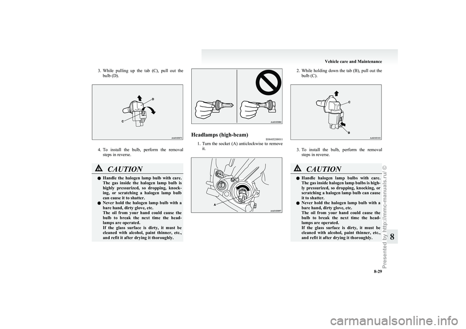
3. While pulling up the tab (C), pull out the
bulb (D). 4. To
install the bulb, perform the removal
steps in reverse. CAUTION
l
Handle
the halogen lamp bulb with care.
The gas inside the halogen lamp bulb is
highly pressurized, so dropping, knock-
ing, or scratching a halogen lamp bulb
can cause it to shatter.
l Never hold the halogen lamp bulb with a
bare hand, dirty glove, etc.
The oil from your hand could cause the
bulb to break the next time the head-
lamps are operated.
If the glass surface is dirty, it must be
cleaned with alcohol, paint thinner, etc.,
and refit it after drying it thoroughly. Headlamps (high-beam)
E08405200011
1. Turn
the socket (A) anticlockwise to remove
it. 2. While
holding down the tab (B), pull out the
bulb (C). 3. To
install the bulb, perform the removal
steps in reverse. CAUTION
l
Handle
halogen lamp bulbs with care.
The gas inside halogen lamp bulbs is high-
ly pressurized, so dropping, knocking, or
scratching a halogen lamp bulb can cause
it to shatter.
l Never hold the halogen lamp bulb with a
bare hand, dirty glove, etc.
The oil from your hand could cause the
bulb to break the next time the head-
lamps are operated.
If the glass surface is dirty, it must be
cleaned with alcohol, paint thinner, etc.,
and refit it after drying it thoroughly. Vehicle care and Maintenance
8-29 8
Presented by http://mmc-manuals.ru/ \251
Page 169 of 193
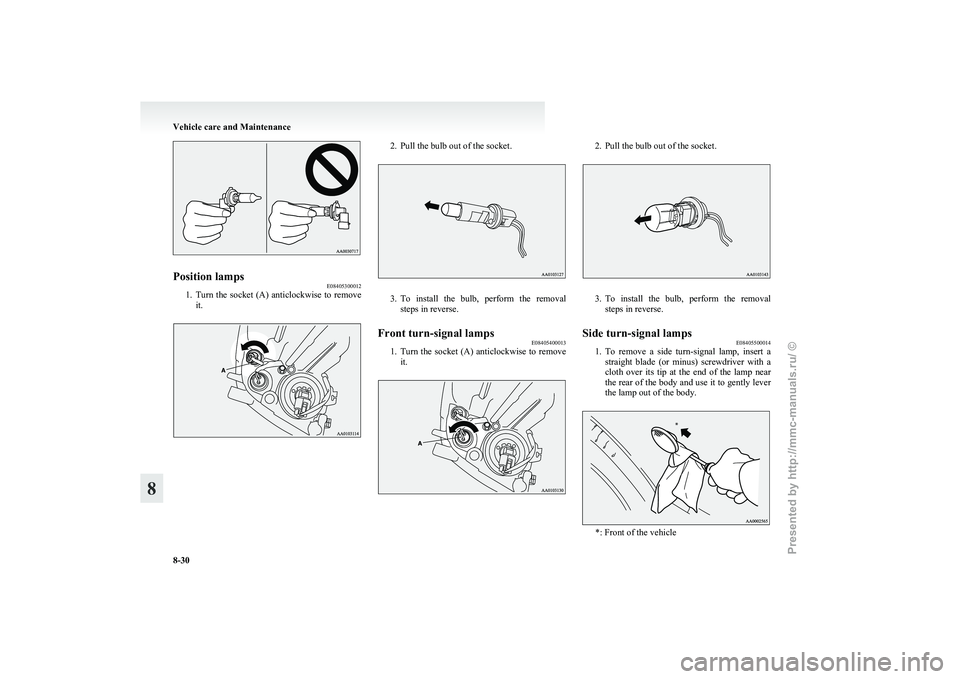
Position lamps
E08405300012
1. Turn the socket (A) anticlockwise to remove
it. 2. Pull the bulb out of the socket.
3. To install the bulb, perform the removal
steps in reverse.
Front turn-signal lamps E08405400013
1. Turn
the socket (A) anticlockwise to remove
it. 2. Pull the bulb out of the socket.
3. To
install the bulb, perform the removal
steps in reverse.
Side turn-signal lamps E08405500014
1. To
remove a side turn-signal lamp, insert a
straight blade (or minus) screwdriver with a
cloth over its tip at the end of the lamp near
the rear of the body and use it to gently lever
the lamp out of the body. *: Front of the vehicleVehicle care and Maintenance
8-30
8 *
Presented by http://mmc-manuals.ru/ \251
Page 170 of 193
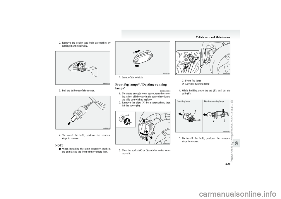
2. Remove the socket and bulb assemblies by
turning it anticlockwise. 3. Pull the bulb out of the socket.
4. To
install the bulb, perform the removal
steps in reverse.
NOTE l When installing the lamp assembly, push in
the end facing the front of the vehicle first. *: Front of the vehicle
Front fog lamps* / Daytime running
lamps* E08405600015
1. To
create enough work space, turn the steer-
ing wheel all the way in the same direction to
the side you wish to replace.
2. Remove the clips (A) by a screwdriver, then lift the cover (B). 3. Turn
the socket (C or D) anticlockwise to re-
move it. C- Front fog lamp
D- Daytime running lamp
4. While
holding down the tab (E), pull out the
bulb (F).
Front fog lamp Daytime running lamp 5. To
install the bulb, perform the removal
steps in reverse. Vehicle care and Maintenance
8-31 8
Presented by http://mmc-manuals.ru/ \251