ECU MITSUBISHI iMiEV 2013 Owner's Manual (in English)
[x] Cancel search | Manufacturer: MITSUBISHI, Model Year: 2013, Model line: iMiEV, Model: MITSUBISHI iMiEV 2013Pages: 258, PDF Size: 13 MB
Page 16 of 258
l
Since the air conditioning (cooling or heat-
ing) consumes power of the traction battery,
its operation results in a shorter cruising
range. Maintain an appropriate temperature.
l Put the selector lever to the “B” (BRAKE) or
“C” (COMFORT) position according to the
road condition. To charge the traction battery
with appropriate use of regenerative braking
can increase the cruising range. Installation of accessories
E00200301003
We
recommend you to consult a MITSUBISHI
MOTORS Authorized Service Point.
l The installation of accessories, optional
parts, etc., should only be carried out within
the limits prescribed by law in your country,
and in accordance with the guidelines and
warnings contained within the documents ac-
companying this vehicle.
l Installing electric components incorrectly
could lead to a fire. See the “Modification/al-
terations to the electrical systems” section
within this owner’s manual.
l Using a cellular phone or radio set inside the
vehicle without an external antenna may
cause electrical system interference, which
could lead to unsafe vehicle operation.
l Tyres and wheels which do not meet specifi-
cations must not be used.
Refer to the “Specifications” section for in-
formation regarding wheel and tyre sizes.
Important points!
Due to large number of accessory and replacement
parts of different manufactures available in the mar-
ket, it is not possible, not only for MITSUBISHI
MOTORS, but also for a MITSUBISHI MOTORS
Authorized Service Point, to check whether the at-
tachment or installation of such parts affects the
overall safety of your MITSUBISHI-vehicle.
Even when such parts are officially authorized, for
example
by a “general operators permit” (an ap-
praisal for the part) or through the execution of the
part in an officially approved manner of construc-
tion, or when a single operation permit following
the attachment or installation of such parts, it can-
not be deduced from that alone, that the driving safe-
ty of your vehicle has not been affected.
Consider also that there basically exists no liability
on the part of the appraiser or the official. Maxi-
mum safety can only be ensured with parts recom-
mended, sold and fitted or installed by a
MITSUBISHI MOTORS authorized Service Point
(MITSUBISHI MOTORS genuine replacement
parts and MITSUBISHI MOTORS accessories).
The same also pertains to modifications of
MITSUBISHI vehicles with respect to the produc-
tion specifications. For safety reasons, do not at-
tempt any modifications other than those that fol-
low the recommendations of a MITSUBISHI
MOTORS authorized Service Point. General information
04
OHAE13E1
Page 54 of 258
Actions to be taken when the MiEV Remote system does not operate correctly
E08303600036
Take
the following actions when the system does not operate correctly. If the system still does not operate correctly after the action(s) have been taken, a system
component may not be working properly. Please consult a MITSUBISHI MOTORS Authorized Service Point to check it. Phenomena Cause Remedy
Charging does not start when the regular charge connector is inserted. “ON” timer has been set.Cancel the “ON” timer.
The regular charge connector is not
locked completely. Lock the regular charge connector se-
curely.
A household electrical outlet, which
the
EV charging cable is connected to,
is shut down.(e.g. disconnected plug) Turn on the household electrical outlet
and make sure the plug is securely con-
nected.
MiEV Remote does not operate normal-
ly. MiEV Remote is not powered on. Batteries in the MiEV Remote are de-
fective or the batteries are discharged.Replace the batteries in the MiEV Re-
mote.
Refer
to “Replacement of batteries for
the MiEV Remote” on page 1-30.
No indication lamps come on when the
remote is turned on.
Melody or buzzer does not sound. Melody or buzzer has been disabled. Enable the melody or buzzer.
Refer
to “To turn on/off melody and
buzzer” on page 1-30.
The following symbol blinks when the
power
supply/communication switch
on the MiEV Remote is pressed.
l ERROR symbol
l symbol
Blinks after about 1 second.
lElectrical noise source is present
in the vicinity of the MiEV Re-
mote.(e.g. personal computer)
l Electrical noise source is present
between the vehicle and the
MiEV Remote. Move away from the noise source.Charging
1-32
1
OHAE13E1
Page 65 of 258
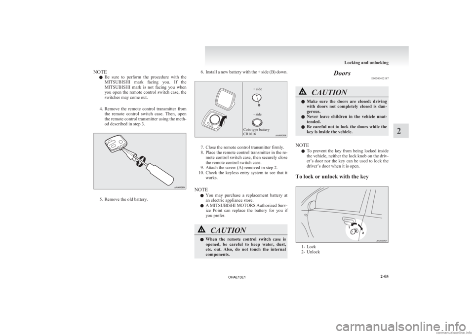
NOTE
l Be
sure to perform the procedure with the
MITSUBISHI mark facing you. If the
MITSUBISHI mark is not facing you when
you open the remote control switch case, the
switches may come out.
4. Remove the remote control transmitter from the remote control switch case. Then, open
the remote control transmitter using the meth-
od described in step 3. 5. Remove the old battery. 6. Install a new battery with the + side (B) down.
Coin type battery
CR1616
- side
+ side 7. Close the remote control transmitter firmly.
8.
Place the remote control transmitter in the re-mote control switch case, then securely close
the remote control switch case.
9. Attach the screw (A) removed in step 2.
10. Check the keyless entry system to see that it works.
NOTE l You may purchase a replacement battery at
an electric appliance store.
l A MITSUBISHI MOTORS Authorized Serv-
ice Point can replace the battery for you if
you prefer. CAUTION
l
When
the remote control switch case is
opened, be careful to keep water, dust,
etc. out. Also, do not touch the internal
components. Doors
E00300402187 CAUTION
l
Make
sure the doors are closed: driving
with doors not completely closed is dan-
gerous.
l Never leave children in the vehicle unat-
tended.
l Be careful not to lock the doors while the
key is inside the vehicle.
NOTE l To
prevent the key from being locked inside
the vehicle, neither the lock knob on the driv-
er’s door nor the key can be used to lock the
driver’s door when it is open.
To lock or unlock with the key 1- Lock
2-
Unlock Locking and unlocking
2-05 2
OHAE13E1
Page 68 of 258
Tailgate
E00301401161WARNING
l When opening and closing the tailgate,
make sure that there are no people near-
by and be careful not to hit your head or
pinch your hands, neck, etc.
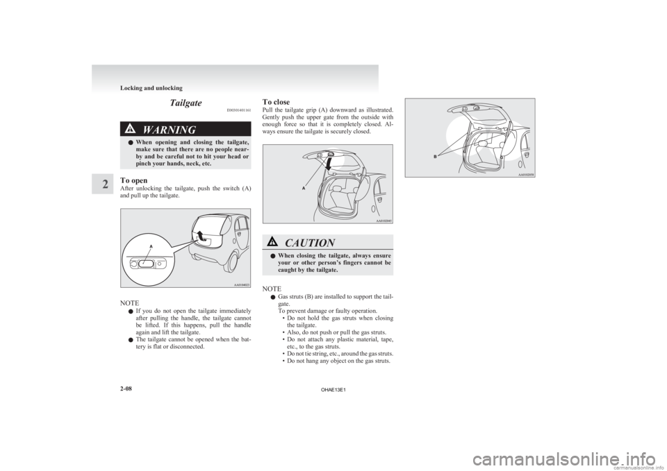
To open
After
unlocking the tailgate, push the switch (A)
and pull up the tailgate. NOTE
l If
you do not open the tailgate immediately
after pulling the handle, the tailgate cannot
be lifted. If this happens, pull the handle
again and lift the tailgate.
l The tailgate cannot be opened when the bat-
tery is flat or disconnected. To close
Pull
the tailgate grip (A) downward as illustrated.
Gently push the upper gate from the outside with
enough force so that it is completely closed. Al-
ways ensure the tailgate is securely closed. CAUTION
l
When
closing the tailgate, always ensure
your or other person’s fingers cannot be
caught by the tailgate.
NOTE l Gas
struts (B) are installed to support the tail-
gate.
To prevent damage or faulty operation. • Do not hold the gas struts when closingthe tailgate.
• Also, do not push or pull the gas struts.
• Do not attach any plastic material, tape, etc., to the gas struts.
• Do not tie string, etc., around the gas struts.
• Do not hang any object on the gas struts. Locking and unlocking
2-08
2
OHAE13E1
Page 73 of 258
Seat adjustment
E00400300633
Adjust
the driver’s seat so that you are comfortable
and that you can reach the pedals, steering wheel,
switches etc. while retaining a clear field of vision. WARNING
l Do
not attempt to adjust the seat while
driving. This can cause loss of vehicle con-
trol and result in an accident. After ad-
justments are made, ensure the seating is
locked in position by attempting to move
the seat forward and rearward without us-
ing the adjusting mechanism.
l Do not allow people or children to ride in
any area of your vehicle that is not equip-
ped with seats and seat belts, and make
sure that everyone travelling in your vehi-
cle is in a seat and wearing a seat belt, or
in the case of a child is strapped in a child
restraint.
l To minimize the risk of personal injury
in the event of a collision or sudden brak-
ing, the seatbacks should always be in the
almost upright position while the vehicle
is in motion. The protection provided by
the seat belts may be reduced significant-
ly when the seatback is reclined. There is
greater risk that the passenger will slide
under the seat belt, resulting in serious in-
jury, when the seatback is reclined. CAUTION
l
Make
sure the seat is adjusted by an
adult or with adult supervision for cor-
rect and safe operation.
l Do not place a cushion or the like be-
tween your back and the seatback while
driving. The effectiveness of the head re-
straints will be reduced in the event of an
accident.
l When sliding the seats, be careful not to
catch your hand or foot. Front seat
E00400400197
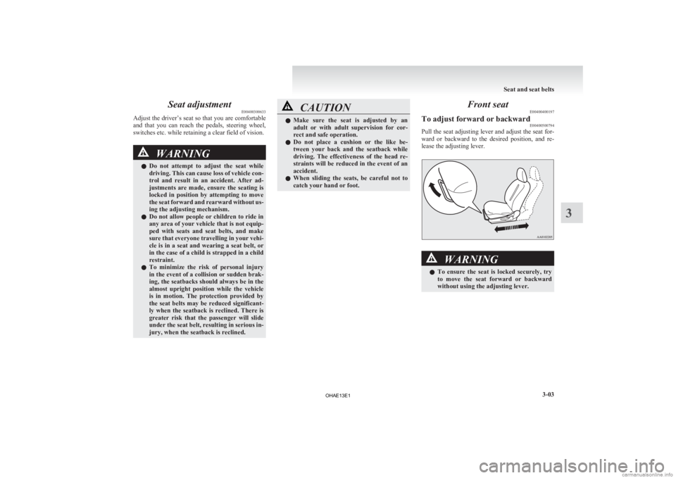
To adjust forward or backward E00400500794
Pull the seat adjusting lever and adjust the seat for-
ward
or backward to the desired position, and re-
lease the adjusting lever. WARNING
l To
ensure the seat is locked securely, try
to move the seat forward or backward
without using the adjusting lever. Seat and seat belts
3-03 3
OHAE13E1
Page 76 of 258
Folding the seatbacks forward
E00401600330
Larger
objects can be loaded into the vehicle if a
seatback is folded forward. CAUTION
l
Do
not stack luggage in the vehicle higher
than the seatback height. Also, firmly se-
cure the luggage.
Serious accidents could result due to un-
restrained objects entering the passenger
compartment during sudden braking.
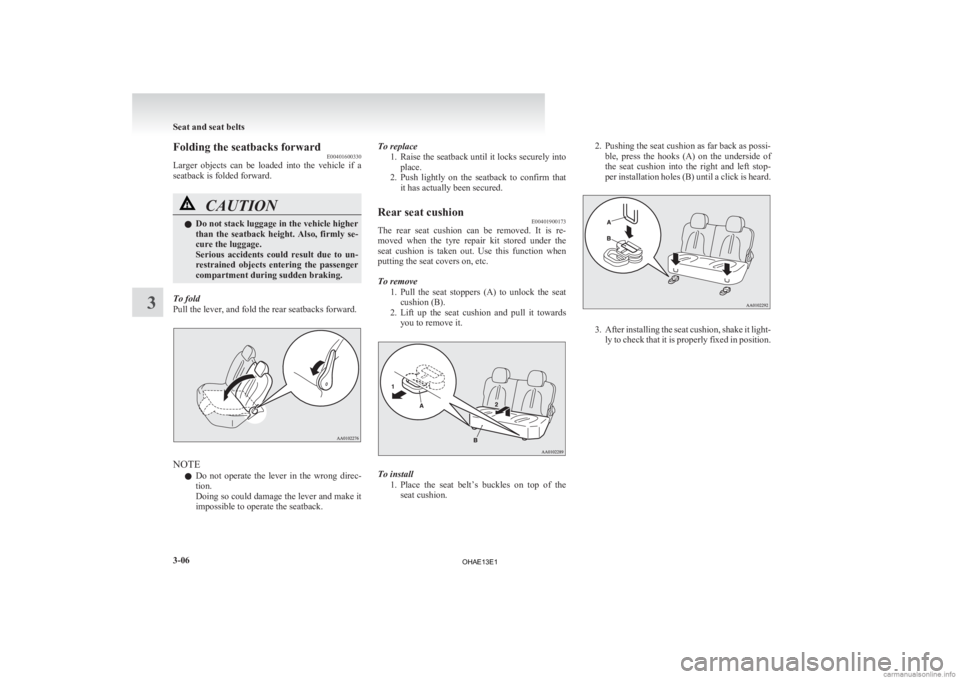
To fold
Pull the lever, and fold the rear seatbacks forward. NOTE
l Do
not operate the lever in the wrong direc-
tion.
Doing so could damage the lever and make it
impossible to operate the seatback. To replace
1. Raise
the seatback until it locks securely into
place.
2. Push lightly on the seatback to confirm that it has actually been secured.
Rear seat cushion E00401900173
The rear seat cushion can be removed. It is re-
moved
when the tyre repair kit stored under the
seat cushion is taken out. Use this function when
putting the seat covers on, etc.
To remove
1. Pull the seat stoppers (A) to unlock the seatcushion (B).
2. Lift up the seat cushion and pull it towards you to remove it. To install
1. Place
the seat belt’s buckles on top of the
seat cushion. 2. Pushing the seat cushion as far back as possi-
ble,
press the hooks (A) on the underside of
the seat cushion into the right and left stop-
per installation holes (B) until a click is heard. 3. After
installing the seat cushion, shake it light-
ly to check that it is properly fixed in position. Seat and seat belts
3-06
3
OHAE13E1
Page 83 of 258
NOTE
l Before
purchasing a child restraint system,
try installing it in the rear seat to make sure
there is a good fit. Because of the location of
the seat belt buckles and the shape of the seat
cushion, it may be difficult to securely install
some manufacturer’s child restraint systems.
If the child restraint system can be pulled for-
ward or to either side easily on the seat cush-
ion after the seat belt has been tightened,
choose another manufacturer’s child restraint
system. WARNING
l When
installing a child restraint system,
refer to the instructions provided by the
manufacturer of the restraint system. Fail-
ure to do so can result in severe or fatal
injury to the child.
l After installation, push and pull the child
restraint system back and forth, and side
to side, to see that it is properly secured.
If the child restraint system is not instal-
led securely, it may cause injury to the
child or other occupants in case of an ac-
cident or sudden stops.
l When the child restraint system is not in
use, keep your child restraint system se-
cured with the seat belt or remove it from
the vehicle in order to prevent it from be-
ing thrown around inside the vehicle dur-
ing an accident.
Depending on the seating position in the ve-
hicle
and the child restraint system that you
have, the child restraint can be attached us-
ing one of the following two locations: • To
the lower anchorage in the rear seat
ONLY if the child restraint has ISOFIX
mountings (See page 3-18).
• To the seat belt (See page 3-19).
Older children E00406700277
Children who have outgrown the child restraint sys-
tem should be seated in the rear seat and wear com-
bination lap shoulder belt.
The lap portion of the belt should be snug and posi-
tioned
low on the abdomen so that it is below the
top of the hip-bone. Otherwise, the belt could in-
trude into the child’s abdomen during an accident
and cause injury. Seat and seat belts
3-13 3
OHAE13E1
Page 89 of 258
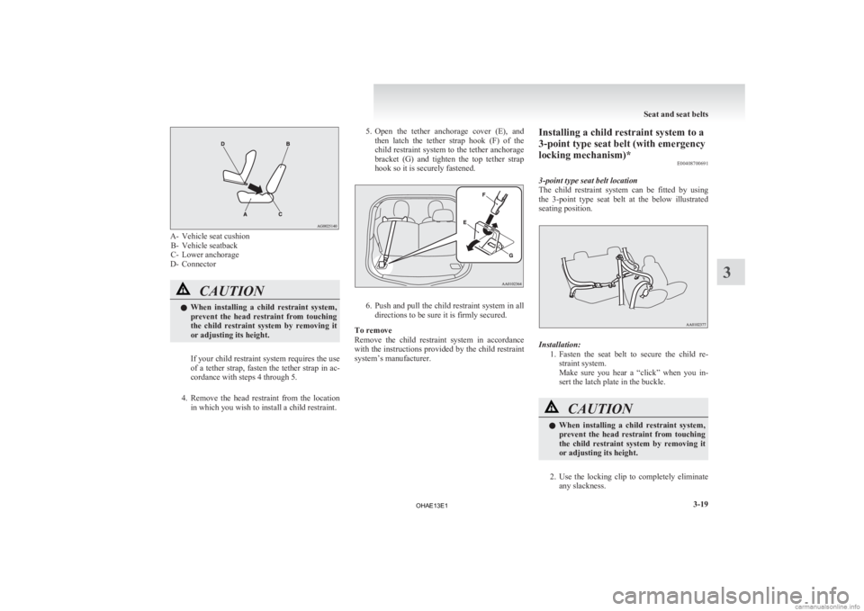
A- Vehicle seat cushion
B- Vehicle seatback
C- Lower anchorage
D- Connector CAUTION
l
When
installing a child restraint system,
prevent the head restraint from touching
the child restraint system by removing it
or adjusting its height.
If your child restraint system requires the use
of
a tether strap, fasten the tether strap in ac-
cordance with steps 4 through 5.
4. Remove the head restraint from the location in which you wish to install a child restraint. 5. Open
the tether anchorage cover (E), and
then latch the tether strap hook (F) of the
child restraint system to the tether anchorage
bracket (G) and tighten the top tether strap
hook so it is securely fastened. 6. Push
and pull the child restraint system in all
directions to be sure it is firmly secured.
To remove
Remove the child restraint system in accordance
with the instructions provided by the child restraint
system’s manufacturer. Installing a child restraint system to a
3-point type seat belt (with emergency
locking mechanism)*
E00408700691
3-point type seat belt location
The
child restraint system can be fitted by using
the 3-point type seat belt at the below illustrated
seating position. Installation:
1. Fasten
the seat belt to secure the child re-
straint system.
Make sure you hear a “click” when you in-
sert the latch plate in the buckle. CAUTION
l
When
installing a child restraint system,
prevent the head restraint from touching
the child restraint system by removing it
or adjusting its height.
2. Use
the locking clip to completely eliminate any slackness. Seat and seat belts
3-19 3
OHAE13E1
Page 90 of 258
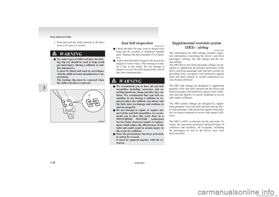
3. Push and pull the child restraint in all direc-
tions to be sure it is secure. WARNING
l For
some types of child restraint, the lock-
ing clip (A) should be used to help avoid
personal injury during a collision or sud-
den manoeuvre.
It must be fitted and used in accordance
with the child restraint manufacturer’s in-
structions.
The locking clip must be removed when
the child restraint is removed. Seat belt inspection
E00406300576
l Check
the belts for cuts, worn or frayed web-
bing and for cracked or deformed metallic
parts. Replace the belt assembly if it is defec-
tive.
l A dirty belt should be cleaned with neutral de-
tergent in warm water. After rinsing in water,
let it dry in the shade. Do not attempt to
bleach or re-dye the belts because this will af-
fect their characteristics. WARNING
l We
recommend you to have all seat belt
assemblies including retractors and at-
taching hardware inspected after any col-
lision. We recommend that seat belt as-
semblies in use during a collision be re-
placed unless the collision was minor and
the belts show no damage and continue to
operate properly.
l Do not attempt to repair or replace any
part of the seat belt assemblies; we recom-
mend you to have this work done by a
MITSUBISHI MOTORS Authorized
Service Point. Incorrect repair or replace-
ment could reduce the effectiveness of the
belts and could result in serious injury in
the event of a collision.
l Once the pretensioner has been activated,
it cannot be re-used.
It must be replaced together with the re-
tractor. Supplemental restraint system
(SRS) - airbag E00407202026
The
information for SRS airbags includes impor-
tant information concerning the driver’s and front
passenger’s airbags, the side airbags and the cur-
tain airbags.
The SRS driver and front passenger airbags are de-
signed to supplement the primary protection of the
driver and front passenger side seat belt systems by
providing those occupants with protection against
head and chest injuries in certain moderate-to-se-
vere frontal collisions.
The SRS side airbags are designed to supplement
properly worn seat belts and provide the driver and
front passenger with protection against chest, abdo-
men and hip injuries in certain moderate-to-severe
side impact collisions.
The SRS curtain airbags are designed to supple-
ment properly worn seat belts and provide the driv-
er and passenger with protection against head inju-
ries in certain moderate-to-severe side impact colli-
sions.
The SRS is NOT a substitute for the seat belts. To
ensure the maximum protection during all types of
collisions and accidents, all occupants, including
the passengers as well as the driver, must wear
their seat belts. Seat and seat belts
3-20
3
OHAE13E1
Page 123 of 258
Safe driving techniques
E00600300635
Driving
safety and protection against injury cannot
be fully ensured. However, we recommend that
you pay extra attention to the following:
Seat belts
Before starting the vehicle, make sure that you and
your passengers have fastened your seat belts.
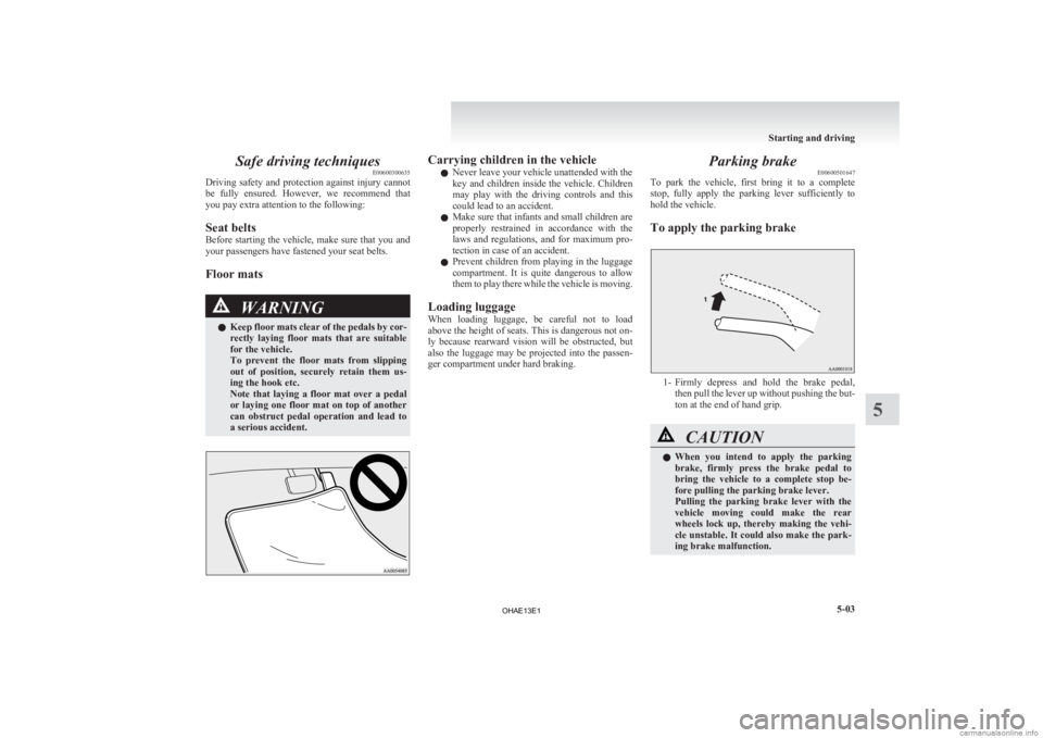
Floor mats WARNING
l Keep
floor mats clear of the pedals by cor-
rectly laying floor mats that are suitable
for the vehicle.
To prevent the floor mats from slipping
out of position, securely retain them us-
ing the hook etc.
Note that laying a floor mat over a pedal
or laying one floor mat on top of another
can obstruct pedal operation and lead to
a serious accident. Carrying children in the vehicle
l Never leave your vehicle unattended with the
key
and children inside the vehicle. Children
may play with the driving controls and this
could lead to an accident.
l Make sure that infants and small children are
properly restrained in accordance with the
laws and regulations, and for maximum pro-
tection in case of an accident.
l Prevent children from playing in the luggage
compartment. It is quite dangerous to allow
them to play there while the vehicle is moving.
Loading luggage
When loading luggage, be careful not to load
above the height of seats. This is dangerous not on-
ly because rearward vision will be obstructed, but
also the luggage may be projected into the passen-
ger compartment under hard braking. Parking brake
E00600501647
To
park the vehicle, first bring it to a complete
stop, fully apply the parking lever sufficiently to
hold the vehicle.
To apply the parking brake 1- Firmly
depress and hold the brake pedal,
then pull the lever up without pushing the but-
ton at the end of hand grip. CAUTION
l
When
you intend to apply the parking
brake, firmly press the brake pedal to
bring the vehicle to a complete stop be-
fore pulling the parking brake lever.
Pulling the parking brake lever with the
vehicle moving could make the rear
wheels lock up, thereby making the vehi-
cle unstable. It could also make the park-
ing brake malfunction. Starting and driving
5-03 5
OHAE13E1