instrument cluster MITSUBISHI iMiEV 2015 Owner's Manual (in English)
[x] Cancel search | Manufacturer: MITSUBISHI, Model Year: 2015, Model line: iMiEV, Model: MITSUBISHI iMiEV 2015Pages: 262, PDF Size: 26.84 MB
Page 3 of 262
Instruments and controls (Driver’s area) 1-1
1
Overview
N00100202573
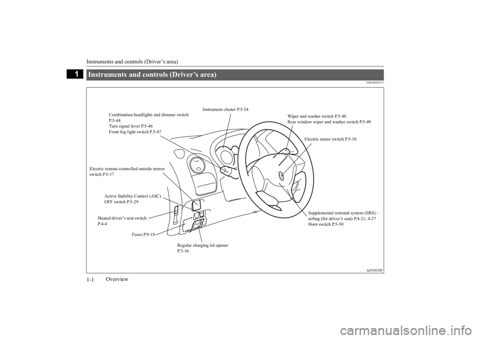
Instruments and controls (Driver’s area)
Wiper and washer switch P.5-48 Rear window wiper and washer switch P.5-49
Instrument cluster P.5-34
Combination headlight
s and dimmer switch
P.5-44 Turn signal lever P.5-46Front fog light switch P.5-47
Electric motor switch P.5-18
Electric remote-controlled outside mirror switch P.5-17
Active Stability Control (ASC) OFF switch P.5-29
Supplemental restraint system (SRS) - airbag (for driver’s seat) P.4-21, 4-27Horn switch P.5-50
Heated driver’s seat switch P. 4 - 4
Fuses P.9-18
Regular charging lid opener P.3-16
BK0209800US.book 1 ページ 2014年1月14日 火曜日 午前9時26分
Page 34 of 262
Regular charging (charging method with rated AC 120 V outlet)
General information/Charging 3-19
3
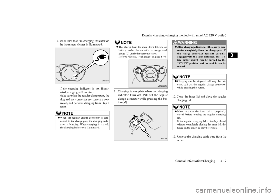
10. Make sure that the charging indicator on
the instrument cluster is illuminated. If the charging indicator is not illumi- nated, charging will not start. Make sure that the regular charge port, theplug and the connector are correctly con- nected, and perform charging from Step 5 again.
11. Charging is complete when the charging
indicator turns off. Pull out the regular charge connector while pressing the but- ton (M).
12. Close the inner lid and close the regular
charging lid.
13. Remove the charging cable plug from the
outlet.
NOTE
When the regular char
ge connector is con-
nected to the charge port, the charging indi-cator is blinking. When
charging is started,
the charging indicator is illuminated.
The charge level for main drive lithium-ion battery can be checked
with the energy level
gauge (L) on the instrument cluster.Refer to “Energy level gauge” on page 5-40.NOTE
LM
WA R N I N G After charging, discon
nect the charge con-
nector completely from the charge port. Ifthe charge connector remains partiallyengaged with the latch unlocked, the elec- tric motor switch can be turned to the “START” position an
d the vehicle can be
moved.NOTE
Charging can be stopped
half way. In this
case, pull out the regular charge connector while pressing the button.NOTE
Make sure that the inner lid is completely closed before closing the regular charging lid.If the regular charging
lid is forcibly closed
without completely clos
ing the inner lid, the
hinge on the inner
lid may be broken.
BK0209800US.book 19 ページ 2014年1月14日 火曜日 午前9時26分
Page 35 of 262
Regular charging (charging method with rated AC 120 V outlet) 3-20 General information/Charging
3
14. Install the cap on the regular charge con-
nector.
N01202501047
You cannot charge the main drive lithium-ionbattery when the main drive lithium-ion bat-tery temperature is -13 °F (-25 °C) or lower. The air conditioning will automatically oper- ate and the main drive lithium-ion batterywill be heated when all the following condi- tions are met.
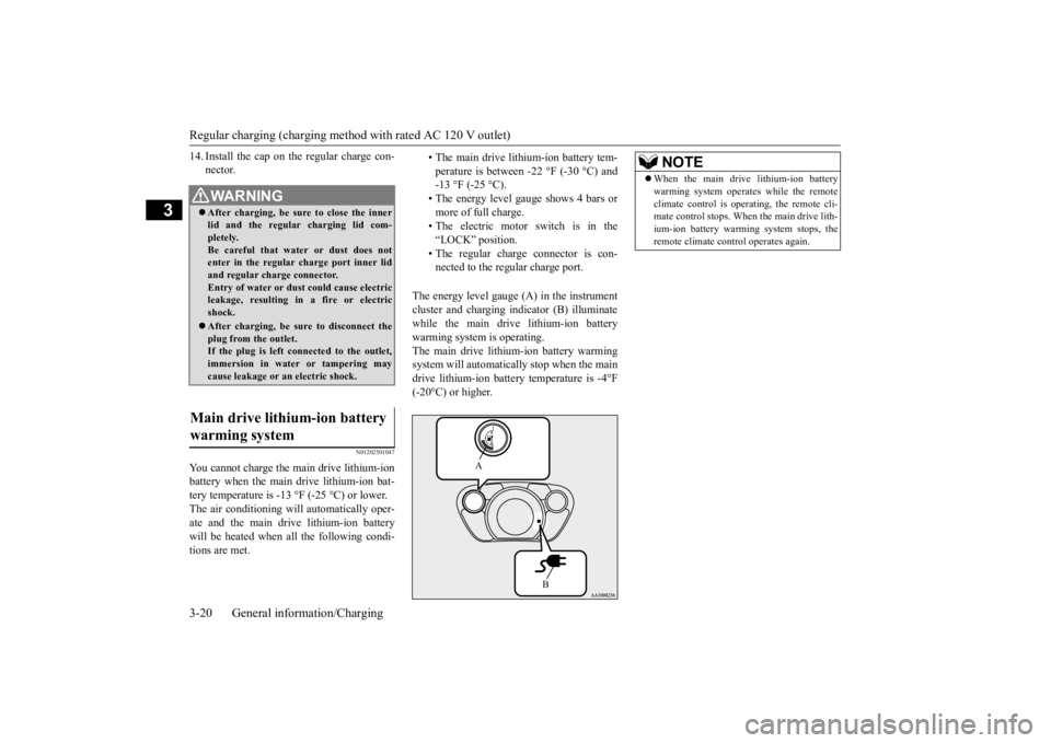
The energy level gauge (A) in the instrument cluster and charging i
ndicator (B) illuminate
while the main drive lithium-ion battery warming system is operating. The main drive lithium-ion battery warmingsystem will automatically stop when the main drive lithium-ion batter
y temperature is -4°F
(-20°C) or higher.
WA R N I N G After charging, be sure to close the inner lid and the regular charging lid com- pletely.Be careful that water or dust does not enter in the regular charge port inner lid and regular charge connector.Entry of water or dust could cause electric leakage, resulting in
a fire or electric
shock. After charging, be sure
to disconnect the
plug from the outlet.If the plug is left connected to the outlet, immersion in water or tampering may cause leakage or an
electric shock.
Main drive lithium-ion battery warming system
• The main drive lithium-ion battery tem- perature is between -22 °F (-30 °C) and -13 °F (-25 °C).• The energy level gauge shows 4 bars or more of full charge. • The electric motor switch is in the“LOCK” position. • The regular charge connector is con- nected to the regular charge port.
A
B
NOTE
When the main drive lithium-ion battery warming system operates while the remoteclimate control is operating, the remote cli-mate control stops. When the main drive lith- ium-ion battery warming system stops, the remote climate cont
rol operates again.
BK0209800US.book 20 ページ 2014年1月14日 火曜日 午前9時26分
Page 41 of 262
Quick charging (charging method with quick charger) 3-26 General information/Charging
3
6. Insert the quick charge connector com- pletely into the quick charge port to begincharging. For connecting and di
sconnecting, follow
the instruction manual for each quickcharger.
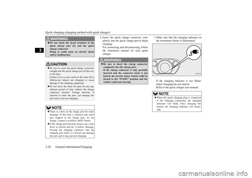
7. Make sure that the charging indicator on the instrument cluster is illuminated. If the charging indicator is not illumi- nated, charging has not started. Refer to the quick charger user manual.
WA R N I N G Do not touch the metal terminal of the quick charge port (E) and the quickcharge connector.Doing so could cause an electric shock and/or malfunction.CAUTION Be sure to insert the quick charge connector straight into the quick charge port all the wayto the base. Failure to do so may result in the main drive lithium-ion battery not charging or causedamage to the charging equipment. Do not leave the inner lid open for any sig- nificant period of ti
me without the charge
connector inserted.
Foreign material, if
allowed to enter the port, can damage theport and/or prevent charging.NOTE
There is a hole on the charge port for water drainage. If this hole
is blocked and water
gets trapped in the charge port, do not charge. Contact a certified i-MiEV dealer. If the charge port becomes frozen, use a hair dryer to defrost and dry it before charging.Forcing the charging connector into the charging port while it
is frozen can damage
the port, and it may prevent charging.
WA R N I N G Be sure to insert the charge connector completely into the charge port. If the charge connector is only partially inserted and the connector latch is notlocked, the electric motor switch could be turned to the “START” position and the vehicle could start moving
NOTE
When the quick charging plug is connected to the charging connection, the chargingindicator will blink.
Once charging has
started, the charging i
ndicator will illumi-
nate.
BK0209800US.book 26 ページ 2014年1月14日 火曜日 午前9時26分
Page 42 of 262
Quick charging (charging method with quick charger)
General information/Charging 3-27
3
8. Charging is complete when the charging indicator turns off.Disconnect the quick charge connector according to the manual of the quick char- ger. 9. Close the inner lid and close the quick charging lid.
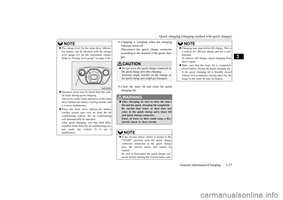
The charge level for the main drive lithium- ion battery can be checked with the energylevel gauge (F) on the
instrument cluster.
Refer to “Energy leve
l gauge” on page 5-40.
Operation noise may be heard from the vehi- cle body during quick charging.This noise comes from operation of the main drive lithium-ion batter
y cooling system, and
it is not a malfunction. Since the main driv
e lithium-ion battery
cooling system uses cool air from the airconditioning system,
the air conditioning
will automatically be operated. After quick charging, you may find dehu-midified water from
the air conditioning sys-
tem under the vehicle. It is not a malfunction.NOTE
F
CAUTION Do not leave the quick charge connected to the quick charge port after charging. Someone might stumble on the charger orthe quick charge port might get damaged.WA R N I N G After charging, be sure to close the inner lid and the quick charging lid completely.Be careful that water or dust does not enter in the quick charge port, inner lid and quick charge connector.Entry of water or dust could cause a fire, electric shock or
short circuit.
NOTE
If the electric motor switch is turned to the “START” position with the quick charge connector connected to the quick chargeport, the electric motor unit cannot be started. Be sure to disconnect
the quick charge con-
nector before starting
the electric motor unit.
Charging may stop before full charge. This is a control for efficient charge and not a mal-function.To achieve full charge, repeat charging from Step 5 again. Make sure that the inner lid is completely closed before closing the quick charging lid. If the quick charging li
d is forcibly closed
without first co
mpletely closing inner lid, the
hinge on the inner
lid may be broken.
NOTE
BK0209800US.book 27 ページ 2014年1月14日 火曜日 午前9時26分
Page 106 of 262
5
Features and controlsBreak-in recommendations ..............................................................5-2 Keys .................................................................................................5-2 Electronic immobilizer (Anti-theft starting system) ........................5-2Keyless entry system .......................................................................5-5 Door locks ........................................................................................5-8 Power door locks ........
...........
...........
...........
...........
...........
.........
.....5-9
Child safety locks for rear door ..........
...........
.........
.........
.........
.....5-10
Liftgate ........................................................................................... 5-11 Theft-alarm system ........................................................................5-12Power window control ...................................................................5-14 Parking brake .................................................................................5-16 Inside rearview mirror ...................................................................5-16Outside rearview mirrors ...............................................................5-17 Electric motor switch .....................................................................5-18 Steering wheel lock ........................................................................5-20Starting the electric motor unit ......................................................5-20 Transmission ..................................................................................5-21 Acoustic vehicle alerting system (AVAS) ......................................5-23Service brake .................................................................................5-24 Brake assist system ........................................................................5-25 Anti-lock braking system ...............................................................5-25Electric power steering system (EPS) ............................................5-27 Active stability control (ASC) .......................................................5-28 Tire pressure monitoring system ....................................................5-30Instrument cluster ..........................................................................5-34 Indicator and warning light package ..............................................5-41 Indicators .......................................................................................5-42Warning lights ................................................................................5-42
Combination headlights and dimmer switch ................................. 5-44 Turn signal lever ............................................................................ 5-46 Hazard warning flasher switch ...................................................... 5-47Front fog light switch .................................................................... 5-47 Wiper and washer switch ............................................................... 5-48 Electric rear window defogger switch ....
...........
...........
...........
...... 5-50
Horn switch ................................................................................... 5-50 Sun visors ...................................................................................... 5-51 12 V power outlet .......................................................................... 5-51Interior lights ................................................................................. 5-52 Storage spaces ................................................................................ 5-54 Cup holder ..................................................................................... 5-55Assist grip ...................................................................................... 5-56
BK0209800US.book 1 ページ 2014年1月14日 火曜日 午前9時26分
Page 121 of 262

Parking brake 5-16 Features and controls
5
N00511400386
To park the vehicle, first bring it to a com- plete stop, fully engage the parking brake, and set the selector le
ver to “P” (PARK) posi-
tion.
When parking on a hill, apply the parking brake and turn the front wheels toward the curb on a downhill grade, away from the curb on an uphill grade.
N00511600287
Adjust the inside rearview mirror only after making any seat adjustme
nts so as to have a
clear view to the rear of the vehicle. Adjust the inside mirror to maximize the view through the rear window. It is possible to move the mirror up and down to adjust its position.
Parking brake To apply 1- Pull the lever up without pushing the
button at the end of hand grip. When the parking brake is set and the electric motor switch is in the “ON”position, the brake warning light in the instrument cluster will come on. Before driving, be sure to release the parking brake.
To release 1- Pull the lever up slightly. 2- Press and hold the button at the end of
the hand grip.
3- Push the lever downward. CAUTION Before driving, be sure that the parking brake is fully released and brake warning light is off.If a vehicle is driven without releasing the parking brake, the brak
es will be overheated,
resulting in ineffective braking and possiblebrake failure.
Inside rearview mirror
WA R N I N G Do not attempt to adjust the inside rear- view mirror while driving. This can be dangerous. Be sure to adjust the mirror before driv-ing.
To adjust the vertical mirror position
BK0209800US.book 16 ページ 2014年1月14日 火曜日 午前9時26分
Page 126 of 262
Transmission
Features and controls 5-21
5
N00513200203 N00513800371
N00513900431
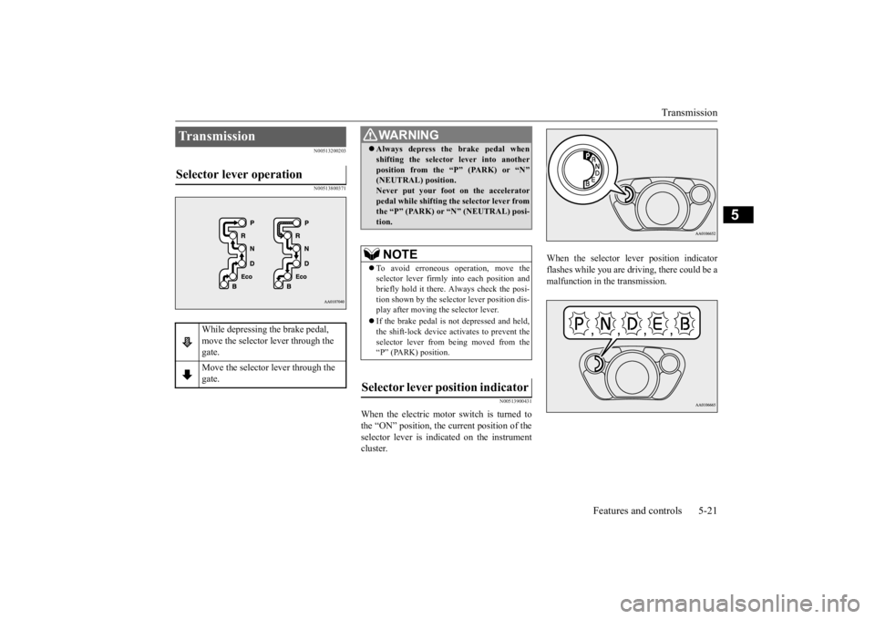
When the electric motor switch is turned to the “ON” position, the current position of the selector lever is indi
cated on the instrument
cluster.
When the selector le
ver position indicator
flashes while you are driv
ing, there could be a
malfunction in the transmission.
Transmission Selector lever operation
While depressing the brake pedal, move the selector lever through the gate. Move the selector lever through the gate.
WA R N I N G Always depress the brake pedal when shifting the selector
lever into another
position from the
“P” (PARK) or “N”
(NEUTRAL) position. Never put your foot on the accelerator pedal while shifting the selector lever fromthe “P” (PARK) or
“N” (NEUTRAL) posi-
tion.NOTE
To avoid erroneous
operation, move the
selector lever firmly into each position andbriefly hold it there. Always check the posi- tion shown by the select
or lever position dis-
play after moving the selector lever. If the brake pedal is not depressed and held, the shift-lock device activates to prevent theselector lever from being moved from the “P” (PARK) position.
Selector lever po
sition indicator
BK0209800US.book 21 ページ 2014年1月14日 火曜日 午前9時26分
Page 129 of 262
Service brake 5-24 Features and controls
5
When the vehicle sp
eed is approximately
2-22 mph (3-35 km/h).
The system will not operate under the follow- ing conditions: When the vehicle sp
eed is approximately
2 mph (3 km/h) or less and the brake pedal is depressed. When the vehicle sp
eed is approximately
22 mph (35 km/h) or more. When the selector lever is in the “P” (PARK) position.
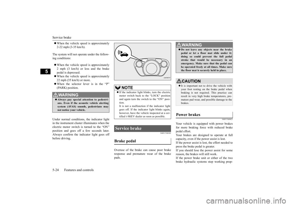
Under normal conditions, the indicator light in the instrument cluster illuminates when theelectric motor switch is turned to the “ON” position and goes off a
few seconds later.
Always confirm the indicator light goes offbefore driving.
N00517500305
Overuse of the brake can cause poor brakeresponse and premature wear of the brakepads.
N00517600423
Your vehicle is equipped with power brakesfor more braking force with reduced brakepedal effort. Your brakes are designed to operate at full capacity, even if the power assist is lost.If the power assist is lost, the effort needed to press the brake pedal is greater. If you should lose the power assist for somereason, the brakes will still work. If the power brake unit or either of the two brake hydraulic systems stop working prop-
WA R N I N G Always pay special attention to pedestri- ans. Even if the acou
stic vehicle alerting
system (AVAS) sounds, pedestrians may not notice your vehicle.
NOTE
If the indicator light blinks, turn the electric motor switch back to the “LOCK” positionand again turn the switch to the “ON” posi- tion. It is not a malfunction if the indicator lightgoes off. If the indica
tor light blinks again,
however, have the vehicl
e inspected at a cer-
tified i-MiEV dealer as soon as possible.
Service brake Brake pedal
WA R N I N G Do not leave any obje
cts near the brake
pedal or let a floor
mat slide under it;
doing so could prevent the full pedalstroke that would be necessary in an emergency. Make sure that the pedal can be operated freely at
all times. Make sure
the floor mat is securely held in place.CAUTION It is important not to drive the vehicle with your foot resting on the brake pedal when braking is not required.
This practice can
result in very high brake temperatures, pre- mature pad wear, and pos
sible damage to the
brakes.
Power brakes
BK0209800US.book 24 ページ 2014年1月14日 火曜日 午前9時26分
Page 139 of 262

Instrument cluster 5-34 Features and controls
5
N00519000375 N00519100246
When the electric motor switch is in the “ON” position, the speedometer indicates thevehicle’s speed in mi
les per hour (mph) or
kilometers per hour (km/h).
N00572000013
It is possible to select
the speedometer’s dis-
play unit. 1. Press the reset button (A) to display the odometer (B). (Refer to “To change the display” on page5-35.)
2. Keep the reset button pressed for 2 sec- onds or longer to change the display unitfrom MPH to km/h or from km/h to MPH.
The display unit for the cruising range will change to match the selected speedometer’sdisplay unit.
Instrument cluster 1- Energy level gauge2- Energy usage indicator3- Odometer/Trip odom
eter/Dash lights
brightness indi
cator/Service
reminder/Cruising ra
nge indicator/Out-
side temperature display
4- Speedometer 5- Reset button/Dash
lights illumination
button/Select
or button
Speedometer
NOTE
The display setting can be changed to the preferred units (miles or km).Refer to “Changing the
display unit” on page
5-34.
Changing the display unit Type 1 Type 2
NOTE
Once the display unit
has changed, keeping
the reset button pressed will not cause thedisplay unit to change again.Speedometer
Cruising range
MPH miles km/h km
BK0209800US.book 34 ページ 2014年1月14日 火曜日 午前9時26分