sensor MITSUBISHI L200 2010 4.G Owners Manual
[x] Cancel search | Manufacturer: MITSUBISHI, Model Year: 2010, Model line: L200, Model: MITSUBISHI L200 2010 4.GPages: 369, PDF Size: 30.72 MB
Page 19 of 369
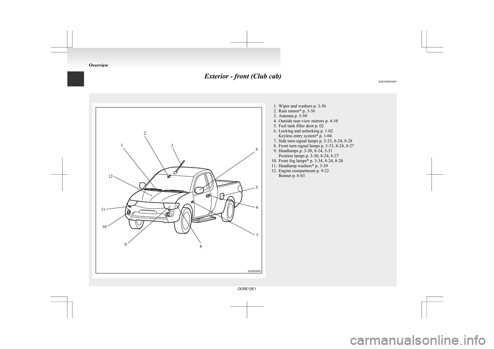
Exterior - front (Club cab)
E00100503965 1. Wiper and washers p. 3-36
2.
Rain sensor* p. 3-36
3. Antenna p. 5-50
4. Outside rear-view mirrors p. 4-10
5. Fuel tank filler door p. 02
6. Locking and unlocking p. 1-02 Keyless entry system* p. 1-04
7. Side turn-signal lamps p. 3-33, 8-24, 8-28
8. Front turn-signal lamps p. 3-33, 8-24, 8-27
9. Headlamps p. 3-30, 8-24, 3-31 Position lamps p. 3-30, 8-24, 8-27
10. Front fog lamps* p. 3-34, 8-24, 8-28
11. Headlamp washers* p. 3-39
12. Engine compartment p. 9-22 Bonnet p. 8-03 Overview12
3 4
5 6
7
8
9
10
11 12
OCRE12E1
Page 21 of 369
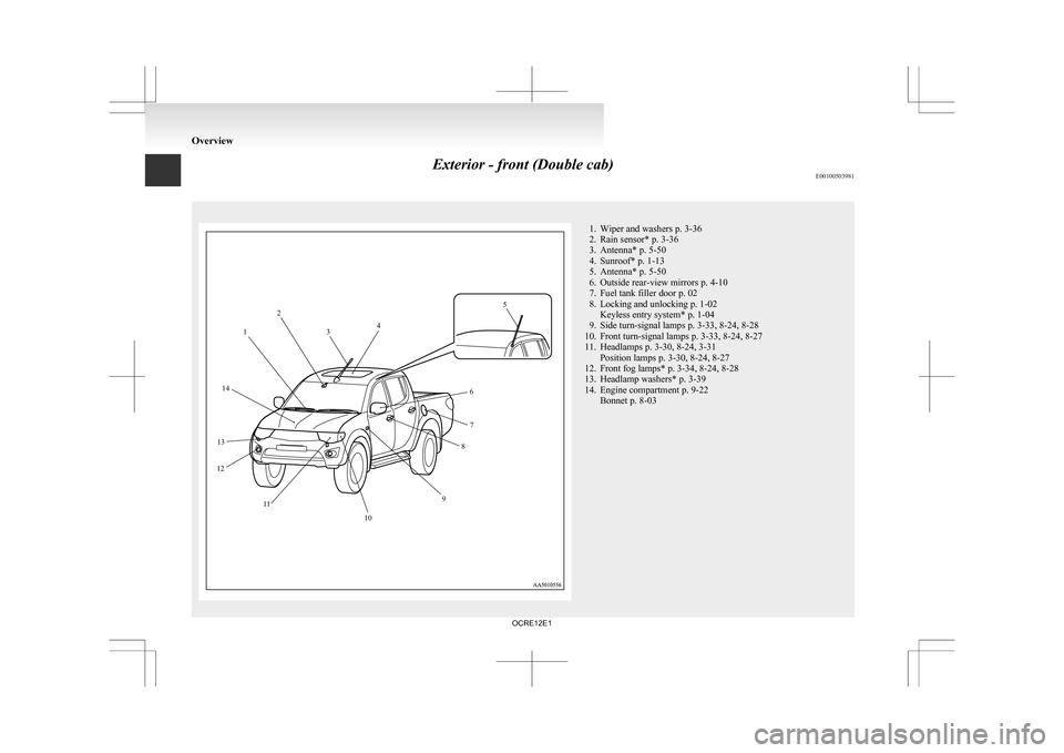
Exterior - front (Double cab)
E00100503981 1. Wiper and washers p. 3-36
2.
Rain sensor* p. 3-36
3. Antenna* p. 5-50
4. Sunroof* p. 1-13
5. Antenna* p. 5-50
6. Outside rear-view mirrors p. 4-10
7. Fuel tank filler door p. 02
8. Locking and unlocking p. 1-02 Keyless entry system* p. 1-04
9. Side turn-signal lamps p. 3-33, 8-24, 8-28
10. Front turn-signal lamps p. 3-33, 8-24, 8-27
11. Headlamps p. 3-30, 8-24, 3-31 Position lamps p. 3-30, 8-24, 8-27
12. Front fog lamps* p. 3-34, 8-24, 8-28
13. Headlamp washers* p. 3-39
14. Engine compartment p. 9-22 Bonnet p. 8-03 Overview12
3 4 5
6 7
8
9
10
11
13
14
12
OCRE12E1
Page 56 of 369
WARNING
l In order to reduce the risk of serious or fa-
tal injury in an accident, always wear
your own seat belt. Do not allow anyone
to ride in your vehicle unless he or she is
also seated and wearing a seat belt. Chil-
dren should additionally be restrained in
a secure child restraint system.
NOTE l When
luggage is placed on the front passen-
ger seat, a sensor in the seat cushion may, de-
pending on the weight and position of the lug-
gage, cause the warning tone to sound and
the warning lamp to come on (Double cab).
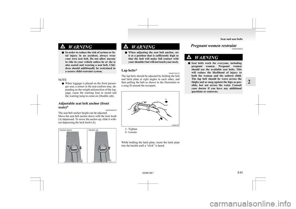
Adjustable seat belt anchor (front
seats)* E00405000299
The seat belt anchor height can be adjusted.
Move
the seat belt anchor down with the lock knob
(A) depressed. To move the anchor up, slide it with-
out depressing the lock knob (A).
Anchor down Anchor up WARNING
l When
adjusting the seat belt anchor, set
it at a position that is sufficiently high so
that the belt will make full contact with
your shoulder but will not touch your neck.
Lap belts* E00405100128
The lap belts should be adjusted by holding the belt
and
latch plate at right angles to each other, and
then pulling the belt as shown in the illustration to
a snug fit around the occupant. 1- Tighten
2-
Loosen
While holding the latch plate, insert the latch plate
into the buckle until a “click” is heard. Pregnant women restraint
E00405600064 WARNING
l Seat
belts work for everyone, including
pregnant women. Pregnant women
should use the available seat belts. This
will reduce the likelihood of injury to
both the woman and the unborn child.
The lap belt should be worn across the
thighs and as snug against the hips as pos-
sible, but not across the waist. Consult
your doctor if you have any additional
questions or concerns. Seat and seat belts
2-11 2
OCRE12E1
Page 57 of 369
Seat belt pretensioner system and
force limiter system* E00405700283
The
driver’s and front passenger’s seat equipped
with an airbag has a pretensioner seat belt.
Pretensioner system E00405801089
The pretensioner system will retract their respec-
tive
seat belts instantaneously, thus maximizing the
seat belt’s effectiveness, if there is a frontal impact
severe enough to injure the driver and/or front pas-
senger and the ignition switch is in the “ON” or
“START” position.
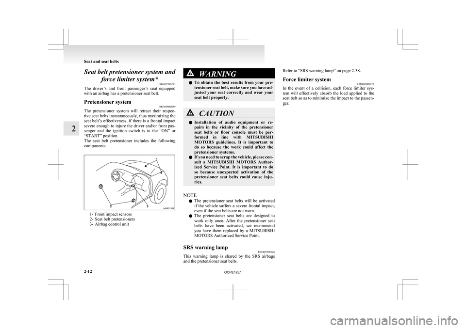
The seat belt pretensioner includes the following
components: 1- Front impact sensors
2-
Seat belt pretensioners
3- Airbag control unit WARNING
l To
obtain the best results from your pre-
tensioner seat belt, make sure you have ad-
justed your seat correctly and wear your
seat belt properly. CAUTION
l
Installation
of audio equipment or re-
pairs in the vicinity of the pretensioner
seat belts or floor console must be per-
formed in line with MITSUBISHI
MOTORS guidelines. It is important to
do so because the work could affect the
pretensioner systems.
l If you need to scrap the vehicle, please con-
sult a MITSUBISHI MOTORS Author-
ized Service Point. It is important to do
so because unexpected activation of the
pretensioner seat belts could cause inju-
ries.
NOTE l The
pretensioner seat belts will be activated
if the vehicle suffers a severe frontal impact,
even if the seat belts are not worn.
l The pretensioner seat belts are designed to
work only once. After the pretensioner seat
belts have been activated, we recommend
you have them replaced by a MITSUBISHI
MOTORS Authorized Service Point.
SRS warning lamp E00405900126
This warning lamp is shared by the SRS airbags
and the pretensioner seat belts. Refer to “SRS warning lamp” on page 2-38.
Force limiter system
E00406000078
In the event of a collision, each force limiter sys-
tem
will effectively absorb the load applied to the
seat belt so as to minimize the impact to the passen-
ger. Seat and seat belts
2-12
2
OCRE12E1
Page 74 of 369
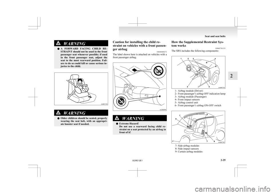
WARNING
l A FORWARD FACING CHILD RE-
STRAINT should not be used in the front
passenger seat whenever possible; if used
in the front passenger seat, adjust the
seat to the most rearward position. Fail-
ure to do so could kill or cause serious in-
juries to the child. WARNING
l Older
children should be seated, properly
wearing the seat belt, with an appropri-
ate booster seat if needed. Caution for installing the child re-
straint on vehicles with a front passen-
ger airbag
E00408800272
The
label shown here is attached on vehicles with a
front passenger airbag. WARNING
l Extreme Hazard!
Do
not use a rearward facing child re-
straint on a seat protected by an airbag in
front of it! How the Supplemental Restraint Sys-
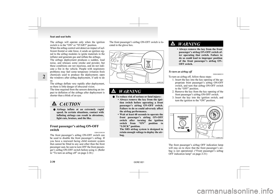
tem works
E00407301352
The SRS includes the following components: 1- Airbag module (Driver)
2- Front
passenger’s airbag OFF indication lamp
3- Airbag module (Passenger)
4- Front impact sensors
5- Airbag control unit
6- Front passenger’s airbag ON-OFF switch 7- Side airbag modules
8- Side impact sensors
9- Curtain airbag modules Seat and seat belts
2-29 2
OCRE12E1
Page 75 of 369
The airbags will operate only when the ignition
switch is in the “ON” or “START” position.
When
the airbag control unit detect an impact of suf-
ficient frontal or side force, it sends an ignition sig-
nal to the airbag modules to ignite materials in the
inflator and generate gas and inflate the airbags.
The airbags deployment produces a sudden, loud
noise, and releases some smoke and powder, but
these conditions are not injurious, and do not indi-
cate a fire in the vehicle. People with respiratory
problems may feel some temporary irritation from
chemicals used to produce the deployment; open
the windows after airbag deployment, if safe to do
so.
The airbags deflate very rapidly after deployment,
so there is little danger of obscured vision.
The time required from the sensors detecting an im-
pact to deflation of the airbags after deployment is
shorter than a blink of an eye. CAUTION
l
Airbags
inflate at an extremely rapid
speed. In certain situations, contact with
inflating airbags can result in abrasions,
light cuts, bruises, and the like.
Front passenger’s airbag ON-OFF
switch E00410100184
The front passenger’s airbag ON-OFF switch can
be
used to disable the front passenger’s airbag. If
you have a rearward facing child restraint system
that cannot be fitted to any seat other than the front
passenger seat, be sure to turn OFF the front passen-
ger’s airbag ON-OFF switch before using it. (Refer
to “To turn an airbag off” on page 2-30.) The front passenger’s airbag ON-OFF switch is lo-
cated in the glove box.
WARNING
l To reduce risk of serious or fatal injury:
• Always
remove the key from the igni-
tion switch before operating a front
passenger’s airbag ON-OFF switch.
Failure to do so could adversely affect
the airbag performance.
• Wait at least 60 seconds to operate the front passenger’s airbag ON-OFF
switch after turning the ignition
switch from “ON” position to
“LOCK” position.
The SRS airbag system is designed to
retain enough voltage to deploy the air-
bag. WARNING
• Always
remove the key from the front passenger’s airbag ON-OFF switch af-
ter operating that switch. Failure to
do so could lead to improper position
of the front passenger’s airbag ON-
OFF switch.
To turn an airbag off E00410600219
To turn an airbag off, follow these steps:
1. Insert
the key into the key opening of the ap-
propriate front passenger’s airbag ON-OFF
switch, and turn that airbag ON-OFF switch
to the “OFF” position.
2. Remove the key from the key opening of the front passenger’s airbag ON-OFF switch.
3. Insert the key into the ignition switch, and turn the ignition to the “ON” position. The front passenger’s airbag OFF indication lamp
will
stay on to show that the front passenger’s air-
bag is not operational. (“Front passenger’s airbag
OFF indication lamp” on page 2-31) Seat and seat belts
2-30
2
OCRE12E1
Page 115 of 369
Combination headlamps and
dipper switch E00506002129
Headlamps
NOTE l Do
not leave the headlamps and other lamps
on for a long time while the engine is station-
ary (not running). A run-down battery could
result.
l When it rains or when the vehicle has been
washed, the inside of the lens sometimes be-
comes foggy. This is the same phenomenon
as when window glass mists up on a humid
day, and does not indicate a functional prob-
lem. When the lamp is switched on, the heat
will remove the fog. However, if water gath-
ers inside the lamp, we recommend you to
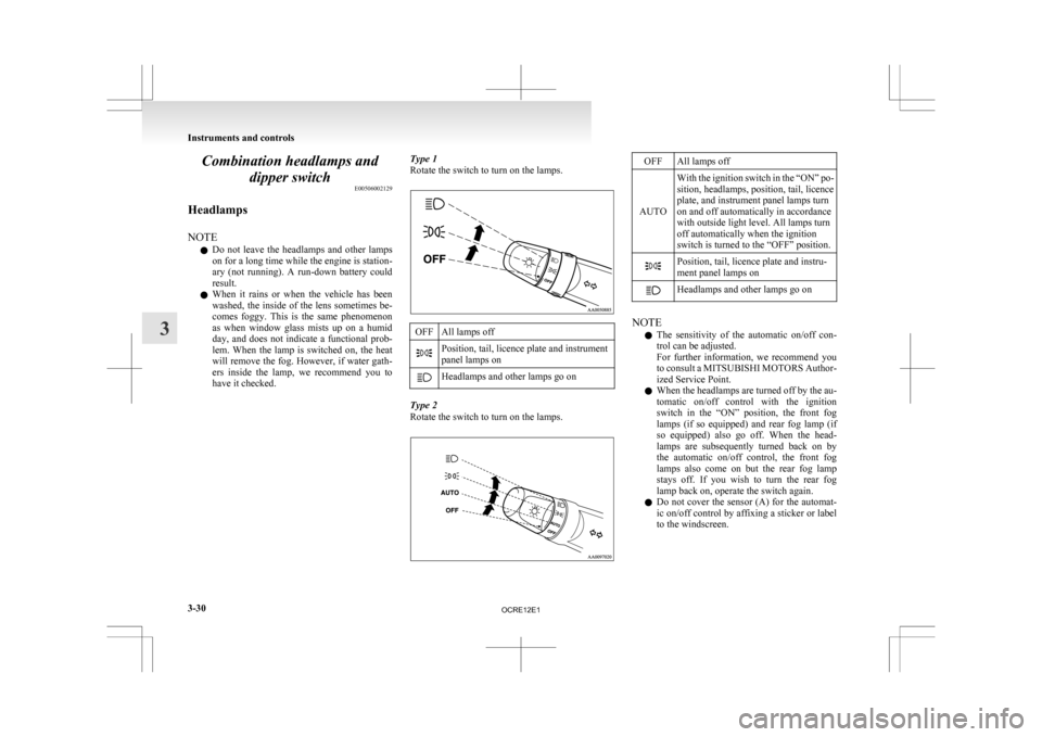
have it checked. Type 1
Rotate the switch to turn on the lamps. OFF All lamps off
Position, tail, licence plate and instrument
panel lamps on
Headlamps and other lamps go on
Type 2
Rotate the switch to turn on the lamps. OFF All lamps off
AUTO With the ignition switch in the “ON” po-
sition, headlamps, position, tail, licence
plate, and instrument panel lamps turn
on and off automatically in accordance
with outside light level. All lamps turn
off automatically when the ignition
switch is turned to the “OFF” position. Position, tail, licence plate and instru-
ment panel lamps on
Headlamps and other lamps go on
NOTE
l The
sensitivity of the automatic on/off con-
trol can be adjusted.
For further information, we recommend you
to consult a MITSUBISHI MOTORS Author-
ized Service Point.
l When the headlamps are turned off by the au-
tomatic on/off control with the ignition
switch in the “ON” position, the front fog
lamps (if so equipped) and rear fog lamp (if
so equipped) also go off. When the head-
lamps are subsequently turned back on by
the automatic on/off control, the front fog
lamps also come on but the rear fog lamp
stays off. If you wish to turn the rear fog
lamp back on, operate the switch again.
l Do not cover the sensor (A) for the automat-
ic on/off control by affixing a sticker or label
to the windscreen. Instruments and controls
3-30
3
OCRE12E1
Page 121 of 369
Wiper and washer switch
E00507101191CAUTION
l
If the washer is used in cold weather, the
washer fluid sprayed against the glass
may freeze, which may hinder visibility.
Warm the glass with the defroster or rear
window demister before using the washer.
Windscreen wipers E00516900303
Except for vehicles equipped with rain sensor
The windscreen wipers can be operated with the ig-
nition switch in the “ON” or “ACC” position.
If
the blades are frozen to the windscreen, do not
operate the wipers until the ice has melted and the
blades are freed, otherwise the wiper motor may be
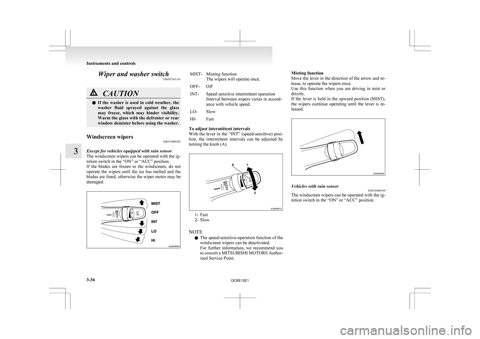
damaged. MIST- Misting function
The wipers will operate once.
OFF- Off
INT- Speed sensitive intermittent operation Interval
between wipers varies in accord-
ance with vehicle speed.
LO- Slow
HI- Fast
To adjust intermittent intervals
With
the lever in the “INT” (speed-sensitive) posi-
tion, the intermittent intervals can be adjusted by
turning the knob (A). 1- Fast
2-
Slow
NOTE l The speed-sensitive-operation function of the
windscreen wipers can be deactivated.
For further information, we recommend you
to consult a MITSUBISHI MOTORS Author-
ized Service Point. Misting function
Move
the lever in the direction of the arrow and re-
lease, to operate the wipers once.
Use this function when you are driving in mist or
drizzle.
If the lever is held in the upward position (MIST),
the wipers continue operating until the lever is re-
leased. Vehicles with rain sensor
E00526400369
The windscreen wipers can be operated with the ig-
nition switch in the “ON” or “ACC” position. Instruments and controls
3-36
3
OCRE12E1
Page 122 of 369
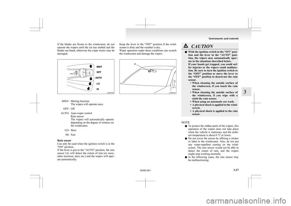
If the blades are frozen to the windscreen, do not
operate
the wipers until the ice has melted and the
blades are freed, otherwise the wiper motor may be
damaged. MIST- Misting function
The wipers will operate once.
OFF- Off
AUTO- Auto-wiper control Rain sensor
The
wipers will automatically operate
depending on the degree of wetness on
the windscreen.
LO- Slow HI- Fast
Rain sensor
Can
only be used when the ignition switch is in the
“ON” position.
If the lever is put in the “AUTO” position, the rain
sensor (A) will detect the extent of rain (or snow,
other moisture, dust, etc.) and the wipers will oper-
ate automatically. Keep the lever in the “OFF” position if the wind-
screen is dirty and the weather is dry.
Wiper
operation under these conditions can scratch
the windscreen and damage the wipers. CAUTION
l
With
the ignition switch in the “ON” posi-
tion and the lever in the “AUTO” posi-
tion, the wipers may automatically oper-
ate in the situations described below.
If your hands get trapped, you could suf-
fer injuries or the wipers could malfunc-
tion. Be sure to turn the ignition switch to
the “OFF” position or move the lever to
the “OFF” position to deactivate the rain
sensor. • When cleaning the outside surface ofthe windscreen, if you touch the rain
sensor.
• When cleaning the outside surface of the windscreen, if you wipe with a
cloth the rain sensor.
• When using an automatic car wash.
• A physical shock is applied to the wind- screen.
• A physical shock is applied to the rain sensor.
NOTE l To
protect the rubber parts of the wipers, this
operation of the wipers does not take place
when the vehicle is stationary and the ambi-
ent temperature is about 0 °C or lower.
l Do not cover the sensor by affixing a sticker
or label to the windscreen. Also, do not put
any water-repellent coating on the wind-
screen. The rain sensor would not be able to
detect the extent of rain, and the wipers
might stop working normally.
l In the following cases, the rain sensor may
be malfunctioning. Instruments and controls
3-37 3
OCRE12E1
Page 123 of 369
Have the vehicle inspected at a
MITSUBISHI
MOTORS Authorized Service
Point. • When the wipers operate at a constant in-terval despite changes in the extent of rain.
• When the wipers do not operate even though it is raining.
l The wipers may automatically operate when
things such as insects or foreign objects are
affixed to the windscreen on top of the rain
sensor or when the windscreen is frozen. Ob-
jects affixed to the windscreen will stop the
wipers when the wipers cannot remove them.
To make the wipers operate again, place the
lever in the “LO” or “HI” position.
Also, the wipers may operate automatically
due to strong direct sunlight or electromag-
netic wave. To stop the wipers, place the lev-
er in the “OFF” position.
l Contact a MITSUBISHI MOTORS Author-
ized Service Point when replacing the wind-
screen or reinforcing the glass around the sen-
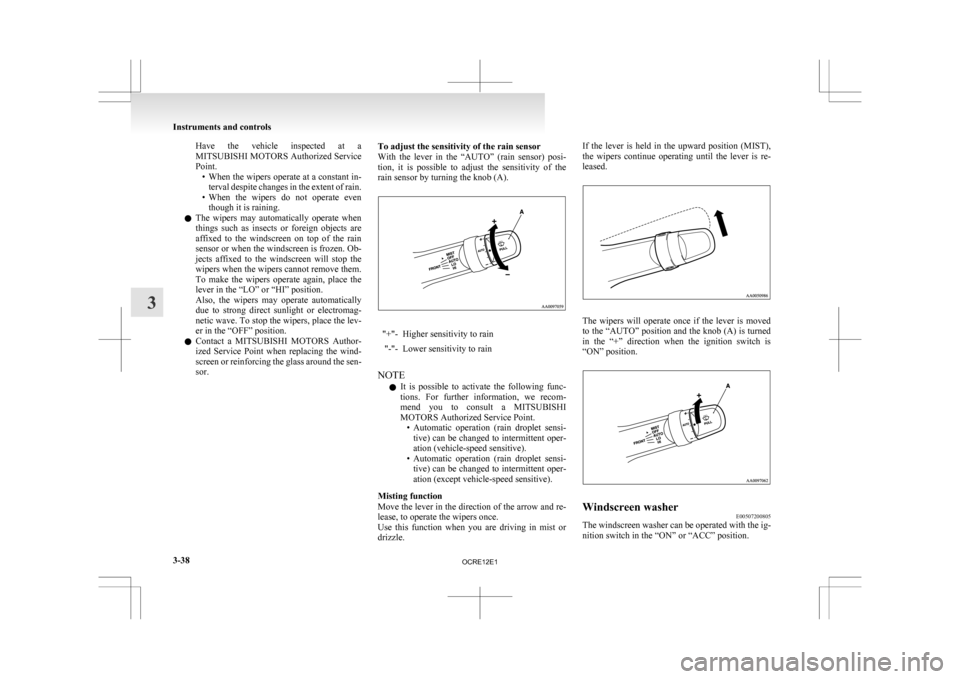
sor. To adjust the sensitivity of the rain sensor
With
the lever in the “AUTO” (rain sensor) posi-
tion, it is possible to adjust the sensitivity of the
rain sensor by turning the knob (A). "+"- Higher sensitivity to rain
"-"- Lower sensitivity to rain
NOTE l It
is possible to activate the following func-
tions. For further information, we recom-
mend you to consult a MITSUBISHI
MOTORS Authorized Service Point. • Automatic operation (rain droplet sensi-tive) can be changed to intermittent oper-
ation (vehicle-speed sensitive).
• Automatic operation (rain droplet sensi- tive) can be changed to intermittent oper-
ation (except vehicle-speed sensitive).
Misting function
Move the lever in the direction of the arrow and re-
lease, to operate the wipers once.
Use this function when you are driving in mist or
drizzle. If the lever is held in the upward position (MIST),
the
wipers continue operating until the lever is re-
leased. The wipers will operate once if the lever is moved
to
the “AUTO” position and the knob (A) is turned
in the “+” direction when the ignition switch is
“ON” position. Windscreen washer
E00507200805
The windscreen washer can be operated with the ig-
nition switch in the “ON” or “ACC” position. Instruments and controls
3-38
3
OCRE12E1